
Related Manuals for MTS Systems Landmark 370 Series


Summary of Contents for MTS Systems Landmark 370 Series
- Page 1 MTS Landmark® Test System Operation Using MTS FlexTest® Controller Software and MTS TestSuite® MPX Testing Software 100-275-889 C...
- Page 2 Aero ST, Aero-90, AeroPro, Criterion, cRPC, Exceed, First Road, Landmark, MAST, MicroProfiler, MPT, MTS Exceed, MTS Fundamentals, MTS TestSuite, ReNew, SilentFlo, TempoGuard, TestLine, Tytron, Virtual Test Lab, and VTL are trademarks of MTS Systems Corporation within the United States. These trademarks may be registered in other countries.
-
Page 3: Table Of Contents
Contents Technical Support How to Get Technical Support Start with your manuals Technical support methods Outside the U.S. Before You Contact MTS Know your site number and system number Know information from prior technical assistance Identify the problem Know relevant computer information Know relevant software information If You Contact MTS by Phone Identify system type... - Page 4 Contents Hardware Manuals Software Help Documentation Access on MTS.com System Overview Load Frame Overview Introduction Component Identification Load Frame Controls Overview Control Panel Software Overview MTS FlexTest (Series 793) Controller Software - Station Manager Application MTS TestSuite Test Software - MTS Multipurpose (MP) Express Application Key Concepts About This Chapter Understanding Your MTS Software...
- Page 5 Contents Positioning the Actuator to Install the Specimen Optimizing System Response Before Testing Why Tuning Is Beneficial Loop Tuning for the Example Test Understanding and Resolving Error Conditions Using Application Logs to Identify Error Conditions Running the Example HCF Test About This Chapter Adapting This Chapter to Your System Test Procedure Overview...
- Page 6 Contents Run the Test Review the Results Generate a Report Save the Test and Minimize MPX Remove the Specimen Remove Displacement Limits Switch to Running Max/Min Displacement and Force Meters If Appropriate, Remove the Intact Specimen If Appropriate, Remove the Broken Specimen Recover from a Tripped Limit If Necessary, Recover from a Tripped Force Limit If Necessary, Recover from a Tripped Displacement Limit...
-
Page 7: Technical Support
Technical Support Technical Support How to Get Technical Support Start with your manuals The manuals supplied by MTS provide most of the information you need to use and maintain your equipment. If your equipment includes software, look for online help and README files that contain additional product information. -
Page 8: Know Information From Prior Technical Assistance
Technical Support When you have more than one MTS system, the system job number identifies your system. You can find your job number in your order paperwork. Example system number: US1.42460 Know information from prior technical assistance If you have contacted MTS about this problem before, we can recall your file based on the: MTS case number Name of the person who helped you Identify the problem... -
Page 9: If You Contact Mts By Phone
Technical Support If You Contact MTS by Phone A Call Center agent registers your call before connecting you with a technical support specialist. The agent asks you for your: Site number Email address Name Company name Company address Phone number where you can be reached If your issue has a case number, please provide that number. -
Page 10: After You Call
Technical Support After you call MTS logs and tracks all calls to ensure that you receive assistance for your problem or request. If you have questions about the status of your problem or have additional information to report, please contact Technical Support again and provide your original case number. Problem Submittal Form Use the Problem Submittal Form to communicate problems with your software, hardware, manuals, or service that are not resolved to your satisfaction through the technical support process. -
Page 11: Preface
Preface Preface Before You Begin Safety first! Before you use your MTS product or system, read and understand the safety information provided with your system. Improper installation, operation, or maintenance can result in hazardous conditions that can cause severe personal injury or death, or damage to your equipment and specimen. Again, read and understand the safety information provided with your system before you continue. -
Page 12: Other Special Text Conventions
Preface Other special text conventions Important: Important notices provide information about your system that is essential to its proper function. While not safety-related, if the important information is ignored, test results may not be reliable, or your system may not operate properly. Note: Notes provide additional information about operating your system or highlight easily overlooked information. -
Page 13: Safety
Safety Safety General Safety Practices Safety Practices Before Operating the System Safety Practices While Operating the System Load Unit Hazard Labels Landmark™ Test System Operation... -
Page 14: General Safety Practices
Safety General Safety Practices If you have system related responsibilities (that is, if you are an operator, service engineer, or maintenance person), you should study this manual carefully before you attempt to perform any test system procedure. You should receive training on this system or a similar system to ensure a thorough knowledge of your equipment and the safety issues that are associated with its use. - Page 15 Safety Read all manuals Study the contents of this manual and the other manuals provided with your system before attempting to perform any system function for the first time. Procedures that seem relatively simple or intuitively obvious can require a complete understanding of system operation to avoid unsafe or dangerous situations.
- Page 16 Safety Know electrical hazards When the system electrical power is turned on, minimize the potential for electrical shock hazards. Wear clothing and use tools that are properly insulated for electrical work. Avoid contact with exposed wiring or switch contacts. Whenever possible, turn off electrical power when you work on or in proximity to any electrical system component.
- Page 17 Safety components that contain pressurized gas. When you bleed a gas or remove a fitting, hose, or component that contains a gas, remember that many gases cannot support life. Therefore, as the ratio of released gas to oxygen increases, so does the potential for suffocation. Wear appropriate safety devices to protect your hearing.
- Page 18 Safety Protect all system hoses and cables from sharp or abrasive objects that can cause the hose or cable to fail. Use a cable cover or cable tray where cables are in traffic locations. Never walk on hoses or cables or move heavy objects over them.
-
Page 19: Safety Practices While Operating The System
Safety Provide adequate ventilation Make sure work and maintenance areas are adequately ventilated to minimize the risks associated with the collection of hazardous fumes (such as vaporized hydraulic fluid). This is of special concern in confined areas where hydraulic equipment is operating at high pressure in confined areas. Provide means to access out-of-reach components Make sure you can access system components that might be out of reach while standing on the floor. - Page 20 Safety Reset/Override button is a software function that can be used to temporarily override an interlock while attempting to gain control of the system. Know system limits Never rely on system limits such as mechanical limits or software limits to protect you or any personnel. System limits are designed to minimize the chance of accidental damage to test specimens or to equipment.
-
Page 21: Load Unit Hazard Labels
Safety and hoses; shorted wires; overstressed feedback devices; and damaged components within the servocontrol loop). Eliminate any condition that could cause unexpected actuator motion. Do not use RF transmitters Keep radio frequency (RF) transmitters away from the workstation computers, remote terminals, and electronics consoles. - Page 22 Safety Hazard Labels Rest of World (part number 100-164-565) Icon Description Failure to follow operating instructions can cause death or serious injury. Read and understand the operator’s manual before using this machine. Moving parts can crush and cut. Keep hands clear while operating machine. Pushing or striking load frame may cause it to tip over.
- Page 23 Safety Icon Description Flying debris and loud noise hazard. Wear ear and eye protection. Hydraulic pressure beyond rated working pressure can rupture components, cause severe personal injury, and damage equipment. Do not exceed 21 MPa (3000 psi) rated working pressure. Hazard Label for HSM Needle Valve Adjustment Icon Description...
- Page 24 Safety Hazard Label for HSM Needle Valve Adjustment Icon Description The HSM needle valve is factory adjusted and should not be adjusted in the field except by MTS Field Service Engineers. Landmark™ Test System Operation...
-
Page 25: System Introduction
System Introduction System Introduction About This Manual About Other MTS Documentation System Overview Load Frame Overview Load Frame Controls Overview Software Overview Landmark™ Test System Operation... -
Page 26: About This Manual
System Introduction About This Manual This manual is for operators of MTS Landmark Systems. It describes the following for a typical MTS Landmark System: Primary components Key concepts you should know before using your system Detailed instructions for running the Example HCF Force Test file (included with your system) on a typical system Best practices for running the example test and other tests on systems that are configured differently than the typical system used as an example in this manual... -
Page 27: System Overview
System Introduction System Overview Station Components Item Name Description MTS FlexTest (Series MTS FlexTest software enables you to control the load frame via the 793) controller controller from the user interface PC. This manual focuses on the software - Station use of the MTS FlexTest Station Manager Application that is used Manager application for station setup. -
Page 28: Load Frame Overview
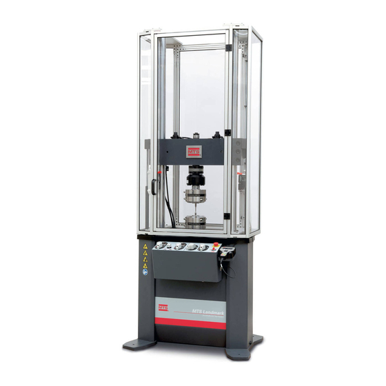
System Introduction Load Frame Overview Introduction The load unit consists of the load frame plus additional parts, such as hydraulic crosshead lifts and control modules. Load units come in different sizes and configurations. The following illustration shows a typical load unit with common accessories. Component Identification Load Frame Front and Rear View Item Component... -
Page 29: Load Frame Controls Overview
System Introduction Item Component Description Load Frame Contains the crosshead lift controls as well as the Emergency Stop switch. Control Module Grip Control Contains hydraulic pressure gages as well as controls to clamp and unclamp Module hydraulic grips. Hydraulic Clamps the crosshead to the columns. (Optional) Crosshead Locks Force Sensor... - Page 30 System Introduction Series 370 Load Unit Controls Item Control Description Upper Item 1 controls clamping and unclamping the optional upper hydraulic grip. Item hydraulic 1A adjusts the upper grip clamping rate. Item 1B is the upper grip pressure grip controls gage.
-
Page 31: Software Overview
System Introduction Series 370 Load Unit Controls (continued) Item Control Description Hydraulic Optional control that raises and lowers the crosshead. The crosshead must not crosshead be moved while it is locked. Load frames without hydraulic positioning require positioning the operator to use a hoist to support and move the crosshead. control Emergency Removes the hydraulic power and stops the test program. - Page 32 System Introduction Setting Up Meters Setting Up a Scope Applying Power to the Station Moving the Actuator (for specimen installation) Using the Function Generator Setting Tuning Parameters The Station Manager application windows associated with each task are shown below. Opening a Station Using the Open Station window, you can select a configuration and a parameter set.
- Page 33 System Introduction Setting Limits Setting limits helps prevent specimen damage and injury. You can set limits using the Limits tab of the Station Setup window. Landmark™ Test System Operation...
- Page 34 System Introduction Setting Up Meters Meters allow you to monitor displacement and forces. Using the following windows, you can set up multiple meters and arrange them to your liking. Meter types include Timed, Running Max/Min, and Peak/Valley. Applying Power to the Station The interlock and power sections of the main window are located together for convenience.
- Page 35 System Introduction Setting Up a Scope The scope provides a graphical display of the channels of your choosing. During station setup, the scope is often used to compare the input signal to the feedback signal. This activity is essential to setting tuning parameters and helps ensure good system response.
-
Page 36: Mts Testsuite Test Software - Mts Multipurpose (Mp) Express Application
System Introduction Setting Tuning Parameters The tuning fork icon (boxed in red) found in the Station Setup window provides access to the tuning tabs. You can enter tuning parameters on the Adjustments tab. MTS TestSuite Test Software - MTS Multipurpose (MP) Express Application Purpose The MTS Multipurpose (MP) Express application is used to perform the following:... - Page 37 System Introduction Selecting a Test Setting Test Parameters Running a Test Generating a Report The MP application windows associated with each task are shown below. Selecting a Test Selecting a test is done via the MTS TestSuite MP Express main window. Setting Test Parameters Once the test is selected, MTS TestSuite MP Express provides you an opportunity to set test parameters via the Setup Variables window.
- Page 38 System Introduction Running a Test Running a test involves clearing any interlock conditions, powering up the HPU and HSM if necessary, and pressing the Run button. MTS TestSuite MP Express allows you to monitor the test using the tabs found in the main window. Generating a Report When the test is complete, you can generate an Excel report based on one of the Excel templates stored with the test.
- Page 39 System Introduction Landmark™ Test System Operation...
-
Page 41: Key Concepts
Key Concepts Key Concepts About This Chapter Understanding Your MTS Software Understanding MTS File Types Understanding the Control Loop Understanding Control Channels and Control Modes Using Detectors and Actions to Protect Yourself and Your Equipment Using the E-Stop Control Understanding the Load Train Positioning the Crosshead to Install the Specimen Positioning the Actuator to Install the Specimen Optimizing System Response Before Testing... -
Page 42: About This Chapter
Key Concepts About This Chapter This chapter, as well as the information in the Safety chapter, contains information you should know before you attempt to run tests with your MTS Landmark System. This information applies to the typical system used as an example in this manual. For information that applies to other tests or system configurations, see the individual component products manuals included in the System Documentation found under the Start Menu on the user interface PC. -
Page 43: Mts Testsuite Test Software And The Mts Tw Express Application
Key Concepts Offsetting the weight of fixtures so those values do not appear in test data Adjusting gain to optimize system response MTS TestSuite Test Software and the MTS TW Express application MTS TestSuite software includes several applications. Depending on your installation, MTS TW Elite, MTS TW Express, and so on are accessible from the Start menu or desktop icons. -
Page 44: Understanding Mts File Types
Key Concepts on what you need to do. For instance, when you have completed preparation of your station, you minimize the Station Manager application. Then you launch MPX, select a test, and start the first test run of the test. When the test run is complete, you minimize MPX, and maximize the Station Manager application to load another specimen. - Page 45 Key Concepts Station File Types File Type Description MTS FlexTest A FlexTest project is a collection of files related to the station Project Files configuration. When you open a configuration, it opens in the context of its parent project. Files associated with configurations, such as sensor calibration files and parameter sets, are linked to configurations within the project directory.
-
Page 46: Creating And Modifying Parameter Sets
Key Concepts Station File Types (continued) File Type Description Sensor Sensor Calibration files (.scf) contain information about system Calibration sensors, including model number, date, calibration type, and Files conditioner information. You use the Station Manager application to select Sensor Calibration files for your Station Configuration. Sensor Calibration files are part of the Parameter Set. -
Page 47: Selecting And Saving Parameter Sets
Key Concepts Concept of the Station Manager Application Creating a Parameter Set Selecting and Saving Parameter Sets You select a Parameter Set when you open your Station Configuration. It is a good idea to save your parameter set periodically during station setup as you make changes in the Station Manager application. -
Page 48: Understanding The Control Loop
Key Concepts Understanding the Control Loop MTS Landmark Test Systems use closed-loop control, and understanding it lays a foundation for many of the topics in this document. Closed-loop control is a basic servomechanism concept of controlling a test, in which a controlling element controls a controlled element. Closed Loop Control Concept Item Description Feedback... - Page 49 Key Concepts Basic Closed-Loop Control in MTS Landmark Systems 1. You input a compressive command by adjusting the Manual Command slider control in the Station Manager application. 2. The Station Manager application (program source) instructs the digital controller to generate a signal that represents the direction and amount of force the actuator needs to apply to the specimen to accommodate your command.
-
Page 50: Understanding Control Channels And Control Modes
Key Concepts Understanding Control Channels and Control Modes Control Channel (For example, Actuator) Control channels command actuator movement by providing a valve driver signal to the servovalve. The servovalve causes the actuator to move, which applies forces to the specimen. Control Modes (For example, Force or Displacement) A control channel includes one or more control modes. -
Page 51: Sensor Limits
Key Concepts Sensor Limits One type of detector is a limit detector for sensor input signals. Each sensor can have a high and a low limit which you can enable separately. When a sensor exceeds (or trips) its upper or lower limit, the selected detector action occurs. -
Page 52: Positioning The Crosshead To Install The Specimen
Key Concepts For load frames with base mounted actuators (as used by the typical system in this manual), the load train consists of all the components between the actuator’s piston rod (the component that moves up and down) and the crosshead. This typically includes the lower grip, the specimen, the upper grip, and the force sensor (load cell), as shown. -
Page 53: Positioning The Actuator To Install The Specimen
Key Concepts Positioning the Actuator to Install the Specimen You typically position the actuator every time you install a specimen. On the typical system used as an example in this manual, you use the Manual Command panel in the Station Manager application to position the actuator. -
Page 54: Using Application Logs To Identify Error Conditions
Key Concepts Using Application Logs to Identify Error Conditions Both the Station Manager and MTS TestSuite TWX applications are equipped with logs to help you identify error conditions. These logs are your window into the state of the system, and your information center for the source of error conditions. -
Page 55: Running The Example Hcf Test
Running the Example HCF Test Running the Example HCF Test About This Chapter Test Procedure Overview Prepare for Specimen Installation Install the Specimen Prepare to Run the Test Run the Example HCF Test Remove the Specimen Recover from a Tripped Limit Landmark™... -
Page 56: About This Chapter
Running the Example HCF Test About This Chapter This chapter describes how to set up and run the Example HCF Test using the typical MTS Landmark system shown in the System Overview section. Adapting This Chapter to Your System If your system contains the same components as the typical system described in this manual, you can follow the instructions without modification to run the Example HCF Test. -
Page 57: Prepare For Specimen Installation
Running the Example HCF Test 3. Prepare to Run the Test “Perform Basic Performance Tuning” on page 79 “Switch to Peak Valley Meters” on page 88 “Adjust Limits for the Test” on page 90 “Show Station Manager Scope and Meters for the Test” on page 91 “Minimize Station Manager”... -
Page 58: Turn On The Station
Running the Example HCF Test Turn on the Station 1. Turn on the computer. 2. Turn on the controller. The controller power switch is located on the back of the controller. Open the Station Manager Application 1. Close any open applications on the computer desktop. This prevents possible confusion from having multiple stations open. - Page 59 Running the Example HCF Test 3. If necessary, select a project. It is common practice to keep all files in Project1. If you find this acceptable, at the Select Project window, select Project1. Otherwise enter your own project name for the project. Note: The Select Project window will not appear if you selected Project1 as the default project when you installed the MTS TestSuite application.
-
Page 60: Verify Calibration Files
Running the Example HCF Test 6. Ensure that the HSM (hydraulic service manifold) is off. Turning the HSM off removes power from the actuator so that it cannot move unexpectedly during load frame inspection or specimen installation. Note: It is acceptable to leave the pump (HPU) on, as it may be needed for other stations and also leaves power to the hydraulic grips for specimen installation. -
Page 61: Set Up Meters For Specimen Installation
Running the Example HCF Test 1. Verify that the correct calibration file for the displacement sensor is in use. A. Select Station Manager > Display > Station Setup >Channels > Landmark 1 (or other depending on your configuration) > Displacement. B. - Page 62 Running the Example HCF Test 2. If more than one meter appears, delete the extra instances so that only one meter remains. To delete a meter, click the meter title bar, and then click the Delete button in the setup menu. 3.
- Page 63 Running the Example HCF Test Use the following parameters: Meter Type — Running Max/Min Channel — Landmark 1 (or other depending on your configuration) Signal — Force Engineering Units — N 5. Set up a Timed Displacement Meter. Use the following parameters: Meter Type —...
-
Page 64: Set Limits For Specimen Installation
Running the Example HCF Test 7. Align the meters. Click the Align Meters button to toggle between different meter alignments. Select an alignment that works for your window layout. Set Limits for Specimen Installation You can reduce the chances of specimen damage or injury by setting limits that control the amount of force read at the sensor. - Page 65 Running the Example HCF Test D. Use the following parameters: Important: The following numbers were appropriate for the example test on a typical system. You will need to adapt these entries to your specimen, test, and system. Landmark 1 Displacement (Upper Limit, Upper Action) — 100 mm, Interlock Landmark 1 Displacement (Lower Limit, Lower Action) —...
-
Page 66: Zero The Force Signal
Running the Example HCF Test 3. Set the Force Lower (Compression) Limit. For specimen installation, select a low compression limit to reduce the chance of specimen damage or injury. While -50 N is shown here as an example, you should use a limit that adheres to your lab's specimen installation guidelines. -
Page 67: Set Initial Tuning Parameters
Running the Example HCF Test 2. Zero the force signal. Upon initial setup, the force signal meter shows the weight of the grip and associated hardware. A. Open the Inputs: Axial Force window by selecting Station Manager >Display > Station Setup > Channels > Landmark 1 (or other depending on your configuration) >... - Page 68 Running the Example HCF Test 1. Select the Tuning user access level. In order to set tuning parameters, select the Tuning rather than Operator user access level. A. Do this by changing the drop-down selection box to Tuning in the Station Manager application main window.
- Page 69 Running the Example HCF Test P Gain — 40 I Gain — 1 D Gain — 0 F Gain — 0 F2 Gain — 0 Proportional FF Gain — 0 FL Filter — Set to maximum positive value Note: The parameters shown are for this Example Test using a hard specimen.
-
Page 70: Install The Specimen
Running the Example HCF Test F Gain — 0 F2 Gain — 0 Proportional FF Gain — 0 FL Filter — Set to maximum positive value 4. Retain the Tuning user access level. Leave the Operator Type selection set to Tuning because you will do more tuning once the specimen is installed. -
Page 71: Position The Actuator Using Displacement Control
Running the Example HCF Test Click the Reset button. If the interlock will not reset, a condition like the enclosure door not being shut, or the actuator velocity limiting switch being in turtle mode, is likely preventing the interlock from resetting. Note: All interlock conditions will not reset until the pump is on. - Page 72 Running the Example HCF Test Warning: Do not move the control slider until the crush zone is clear, and you can monitor actuator movement. Unskilled movement of the actuator can result in machine damage or personal injury. Ensure that the area is clear, that you can see what you are doing, and that you have the necessary skill to proceed safely.
-
Page 73: Zero Displacement
Running the Example HCF Test Manual Command Slider Function Item Description Explanation Drag slider High Gear — Slider movement is proportional with actuator for "high movement. Use with extreme caution. gear" Click Low Gear — Incremental movement based on settings for the slider between control. -
Page 74: Clamp The Specimen In The Lower Grip
Running the Example HCF Test 2. Click the Auto Offset button to zero displacement. Clamp the Specimen in the Lower Grip 1. Clamp the specimen in the lower grip. Using a tool to hold the specimen, clamp the specimen in the lower grip using the controls on the MTS Landmark load frame. - Page 75 Running the Example HCF Test 2. Reset the Force Lower (Compression) Limit. A. Now that your hands are no longer required to be near the specimen, increase the force lower limit to a value that will allow clamping of the specimen in the upper grip. B.
-
Page 76: Position The Crosshead
Running the Example HCF Test Position the Crosshead 1. Adjust the position of the crosshead using the hydraulic controls. Item Description Crosshead Lock Crosshead Lift A. Unlock the crosshead clamps, and then move the crosshead up or down so that there is about 25 mm (1 in) clearance between the upper grip and the specimen. -
Page 77: Switch To Force Control
Running the Example HCF Test 1. Make sure the grip is open and ready to accept the specimen. 2. Use the slider controls to move the specimen up and into the upper grip. Important: Your station setup will determine whether you have to move in the positive or negative direction. -
Page 78: Check And Reset Meter History
Running the Example HCF Test 1. Clamp the specimen in the upper grip. Using the controls on the MTS Landmark load frame, slowly clamp the specimen in the upper grip. 2. If necessary, recover from a tripped limit (otherwise proceed to the next step). Clamping can result in tripping a force or displacement limit. -
Page 79: Prepare To Run The Test
Running the Example HCF Test 2. Reset meter history. Now that specimen installation is complete, reset meter history by navigating to Station Manager >Display > Meters and clicking the Reset button. Prepare to Run the Test Preparing to run the test consists of the following steps: “Perform Basic Performance Tuning”... - Page 80 Running the Example HCF Test 2. Verify initial force tuning parameters. A. To open the Tuning: Ch1 Force window, select Station Manager >Display > Station Setup > Channels > Landmark 1 (or other depending on your configuration) > Force and then click the Tuning Fork button. B.
- Page 81 Running the Example HCF Test 4. Set up a force waveform using the Function Generator. This introduces a force waveform to the specimen. A. In the Station Manager main window, click the Function Generator button. B. Set up a force waveform using the following parameters: Channel —...
- Page 82 Running the Example HCF Test 6. Set up the Scope. Set up a Scope to compare the command signal to the resulting feedback. In the Station Manager main window, click the Signal Scope button. Enlarge the scope if necessary, and then set up the scope as follows: Y1 parameters: Channel —...
- Page 83 Running the Example HCF Test 7. Run the Function Generator. Click the Program Run button to apply the force waveform to the specimen. If necessary, clear any interlock conditions. 8. Adjust P Gain. Insufficient P Gain Landmark™ Test System Operation...
- Page 84 Running the Example HCF Test Correct P Gain Excessive P Gain A. Open the Tuning: Landmark 1 Force window found by selecting Station Manager > Display > Station Setup > Channels > Landmark 1 (or other depending on your configuration) > Force, clicking the Tuning Fork icon, and clicking the Landmark™...
- Page 85 Running the Example HCF Test Adjustments tab. B. Compare your Scope display to the preceding examples of P gain found in the following displays. If necessary, adjust the P gain for the Force channel. Note: The Scope display shows how well the feedback signal is following the command signal.
- Page 86 Running the Example HCF Test A. In the Station Manager main window, click the Function Generator button. B. Stop the Function Generator by clicking the Stop button, and then change the wave shape from ramp to Sine. C. Click the Program Run button to run the sine wave. Important: Do not adjust P gain when you switch to the sine wave form, as instability could result.
- Page 87 Running the Example HCF Test Correct I Gain Excessive I Gain A. Navigate to the Tuning: Landmark 1 Force window found by selecting Station Manager > Display > Station Setup > Channels > Landmark 1 (or other depending on your configuration) > Force, clicking the Tuning Fork button, and clicking the Adjustments tab.
-
Page 88: Switch To Peak Valley Meters
Running the Example HCF Test B. Compare your graph to the examples of I gain found in the following displays. If necessary, adjust the I gain for the Force channel. Note: Do not adjust all the way to zero or you could trip the force limit. 11. - Page 89 Running the Example HCF Test displacement running max/min meter and change the Meter Type to Peak/Valley. 2. Select a Sensitivity. Select a Sensitivity that is about 1/10th of the displayed reading. 3. Fine-tune the Sensitivity. Proper meter sensitivity adjustment enables you to see fluctuations between cycles. When the Sensitivity is correct, the meter will show minor fluctuations with meter updates no faster than the frequency.
-
Page 90: Adjust Limits For The Test
Running the Example HCF Test Adjust Limits for the Test Setting force limits just outside the expected values for the HCF test helps prevent specimen and equipment damage if something unexpected happens during a test run. 1. You can retain the wide displacement limit range set earlier because this example tension test uses no fixturing that requires protection. -
Page 91: Show Station Manager Scope And Meters For The Test
Running the Example HCF Test 2. Adjust force limits so that they are just outside expected values for the HCF test. A. From the Station Manager main window, select Display > Station Setup, and click the Channel Input Signals button. B. -
Page 92: Minimize Station Manager
Running the Example HCF Test Minimize Station Manager The Station Manager application must be running underneath the MPX application in order to run tests. Minimizing the Station Manager application clears the desktop while leaving it running for the MPX application. 1. -
Page 93: Run The Example Hcf Test
Running the Example HCF Test 2. Minimize the Station Manager application. Click the minimize button in the upper right corner of the Station Manager application. 3. Verify that the Station Manager application is still running by checking for it in the task bar. You can maximize Station Manager at any time by clicking the Station Manager button in the task bar. -
Page 94: Open The Mpx Application
Running the Example HCF Test Open the MPX Application 1. Open the MTS Multipurpose (MP) Express application. Select All Programs > MTS TestSuite > Multipurpose Express. Select the Test 1. From the TestSuite main window, select Tests > Example HCF Force Test to load the test. Landmark™... -
Page 95: If Necessary, Correct Any Resource Errors
Running the Example HCF Test If Necessary, Correct Any Resource Errors 1. Ensure that MTS FlexTest (Series 793) and MTS TestSuite resource names match. A. From the MTS TestSuite main window, open the Resources tab by selecting Example HCF Force Test > Resources. B. - Page 96 Running the Example HCF Test 3. Review the status information. Review the status information that appears. If necessary, use the Edit Parameters button to make corrections. Otherwise, click Run Test to continue. Landmark™ Test System Operation...
-
Page 97: Run The Test
Running the Example HCF Test Run the Test 1. Run the test. A. From the MTS TestSuite controller panel, reset the interlock if necessary. B. Power up the HPU and HSM by clicking the Power Low and Power High buttons in sequence. -
Page 98: Review The Results
Running the Example HCF Test Review the Results 1. Review the test results. At the conclusion of the test, click any of the results tabs found in the MTS TestSuite main window for test details. Landmark™ Test System Operation... -
Page 99: Generate A Report
Running the Example HCF Test Generate a Report 1. Generate a report. Landmark™ Test System Operation... -
Page 100: Save The Test And Minimize Mpx
Running the Example HCF Test A. In the MTS TestSuite main window Explorer panel under Test Runs, select the test run for which you want to run a report. B. Right click and select Generate Report. C. Select the template you wish to use and click Generate Report. Save the Test and Minimize MPX The Station Manager application is used to remove the specimen, so the test can be saved and the MPX application minimized. -
Page 101: Remove Displacement Limits
Running the Example HCF Test Remove Displacement Limits 1. Remove displacement limits. Because the actuator may retract at the conclusion of the test, begin by removing the displacement limits. A. From the Station Manager application main window, select Display > Station Setup, and click the Channel Input Signals button. -
Page 102: If Appropriate, Remove The Intact Specimen
Running the Example HCF Test A. In the Station Manager application main window, click the Meters button. B. Click in the title bar of each Peak/Valley meter and change Meter Type to Running Max/Min. 2. Switch to a Running Max/Min Force meter. Also change the force Peak/Valley meters to Running Max/Min Meters to monitor history during specimen removal. - Page 103 Running the Example HCF Test A. From the Station Manager application main window, click the Manual Command button to open the Manual Command window. B. Select the following parameters: Channel — Landmark 1 (or other depending on your configuration) Control Mode — Force Enable Manual Command —...
- Page 104 Running the Example HCF Test Ensure that the area is clear, that you can see what you are doing, and that you have the necessary skill to proceed safely. 6. Retract the actuator. A. In the Station Manager application main window, click the Manual Command button to open the Manual Command window.
-
Page 105: If Appropriate, Remove The Broken Specimen
Running the Example HCF Test 8. Release the lower grip and remove the specimen. Using a tool that keeps your hands clear of the actuator, grasp the specimen and release the lower grip. That completes this Example test. If Appropriate, Remove the Broken Specimen Use this procedure only if the specimen is broken at the conclusion of the test run. -
Page 106: Recover From A Tripped Limit
Running the Example HCF Test Note: The actuator may retract on its own when the HSM turns off due to the interlock condition caused by exceeding the displacement limit. A. In the Station Manager main window, click the Manual Command button to open the Manual Command window. -
Page 107: If Necessary, Recover From A Tripped Force Limit
Running the Example HCF Test “If Necessary, Recover from a Tripped Force Limit” on page 107 “If Necessary, Recover from a Tripped Displacement Limit” on page 110 If Necessary, Recover from a Tripped Force Limit There are a number of possible causes for a tripped force limit. For example: Clamping a grip may result in a force spike higher than expected. - Page 108 Running the Example HCF Test 2. Disable the Force Lower Limit. A. Disable the Force lower limit so that you are able to reposition the grip and reset the interlock. B. Select Station Manager > Display > Station Setup > Channels > Landmark 1 (or other depending on your configuration) >...
- Page 109 Running the Example HCF Test 4. Re-power the HPU and HSM. In the Station Manager application main window, click the Power Low button, and then the Power High button for the HPU and HSM. 5. Reset Force control to zero. In the Station Manager application main window, click the Manual Control button.
-
Page 110: If Necessary, Recover From A Tripped Displacement Limit
Running the Example HCF Test 7. Reset the Lower (Compression) Limit. A. Navigate to Station Manager >Display > Station Setup > Channels > Landmark 1 (or other depending on your configuration) > Force > Limits. B. Enter -50 N in the Lower Limit text box and ensure that Interlock is selected for the Action. - Page 111 Running the Example HCF Test The actuator may have retracted below the lower displacement limit during specimen installation. The actuator may have retracted when the specimen broke at the conclusion of the test. Your test limits may have been insufficient for the test. Rather than cover all possibilities, this section addresses the first case only.
- Page 112 Running the Example HCF Test 3. Reset/Override the Interlock. In the Station Manager application main window, click the Reset/Override button three times to override the Interlock for 21 seconds, and then power up the HPU and HSM. Warning: Do not move the control slider until the crush zone is clear, and you can monitor actuator movement.
- Page 113 Running the Example HCF Test 5. Move the actuator to within acceptable displacement limits. In the Station Manager application main window, click the Manual Control button. Move the actuator to within acceptable limits while the interlock is overridden. Landmark™ Test System Operation...
-
Page 115: Maintenance
Maintenance Maintenance Routine Maintenance Overview Checklist Maintenance Intervals Daily Inspections Landmark™ Test System Operation... -
Page 116: Routine Maintenance Overview Checklist
Maintenance Routine Maintenance Overview Checklist Recommended service to be performed at each running time interval noted Calendar Time using 8 hour Daily Weekly Biweekly Annually Running Time rate per day Running Time-Hours 1000 1,500 2,000 Check that Actuator Platen Area is Clean Monitor Filter Indicators Check Hoses/Cables/Connectors... - Page 117 Maintenance Recommended service to be performed at each running time interval noted (continued) Calendar Time using 8 hour Daily Weekly Biweekly Annually Running Time rate per day Running Time-Hours 1000 1,500 2,000 Crosshead Unlock Causes Program MTS MTS MTS Interlock Load frame Support Airbags/Pads MTS MTS MTS Crosshead Movement is Smooth...
- Page 118 Maintenance Recommended service to be performed at each running time interval noted (continued) Calendar Time using 8 hour Daily Weekly Biweekly Annually Running Time rate per day Running Time-Hours 1000 1,500 2,000 Manifold Hose Connections are Tight MTS MTS MTS Accumulator Connections are Dry MTS MTS MTS Accumulator Connections are Tight...
-
Page 119: Maintenance Intervals
Maintenance Recommended service to be performed at each running time interval noted (continued) Calendar Time using 8 hour Daily Weekly Biweekly Annually Running Time rate per day Running Time-Hours 1000 1,500 2,000 Valve Balance check displacement MTS MTS MTS control Valve Dither Response MTS MTS MTS Verify High/Low Velocity Switch Light... -
Page 120: Daily Inspections
Maintenance Load Unit Maintenance Intervals (continued) What to Do When to Do It Lubricate the crosshead Whenever they begin to be hard to tighten or sticky when loosened. locking bolts When the bolts begin to loosen or tighten stiffly (manual locking crossheads only). - Page 121 Maintenance Hoses must be routed as to avoid direct heat sources, moving or abrasive equipment. Check actuator speed control functionality. If any problems are encountered, they should be repaired before operating the load unit. Landmark™ Test System Operation...
-
Page 123: Decommissioning
Decommissioning Decommissioning Decommission Landmark™ Test System Operation... -
Page 124: Decommission
Decommissioning Decommission The decommissioning process is performed when the system is going to be moved or taken out of service. Disassembly is required when performing either of these tasks. 1. Remove the specimen and fixtures. Large grips should be removed if the load frame is going to be tipped over. - Page 125 Decommissioning Warning: Residual hydraulic pressure can produce a high pressure spray. You could be cut by this spray or hydraulic fluid could be forced into your skin. Do not continue with this procedure unless the system has been isolated from hydraulic pressure for at least 20 minutes.
- Page 126 Decommissioning B. Floorstanding controllers can be lifted onto a suitable cart and moved to a desired location. Landmark™ Test System Operation...
-
Page 127: Index
force 50 Index Manual Command slider 72 manual displacement 72 modes 50, 103 module grip 29 load frame 29 793 software See MTS FlexTest (Series 793) signal 48 controller software controller 27 selecting Station Manager application 59 accumulators 29 turning on 58 actions controls detector 51... - Page 128 Index exclusive control 66 HSM (hydraulic service manifold) 29 extensometer maintaining 117 calibration interval 120 turning off 60, 104 hydraulic service manifold 29 maintaining 117 turning off 60, 104 feedback 48 file extensions .cfg 45 .scf 46 I Gain files adjusting 86 configuration 45 initial tuning 67...
- Page 129 Index LVDT (displacement) sensor 29 calibration interval 120 offset 67 calibration verification 61 auto 73 overriding interlocks 112 overview maintenance testing 56 intervals 119 routine checklist 116 manual P Gain overview 26 adjusting 83 Manual Command parameter sets 45 disabling 80 identifying 60 setting 111 password...
- Page 130 Index sensor tuning{see}tuning 79 calibration files 46 System Documentation CD 26 displacement (LVDT) 29 calibration interval 120 calibration verification 61 technical support 7 extensometer template calibration interval 120 reports 99 force (load cell) 52 test calibration interval 120 results 98 calibration verification 61 running 97 limits 51...
- Page 131 Index zero sensor Auto Offset 73 sensor{see}Auto Offset 67 Landmark™ Test System Operation...
- Page 134 MTS Systems Corporation 14000 Technology Drive Eden Prairie, MN 55344-2290 USA Email: info@mts.com www.mts.com ISO 9001 Certified Quality Management System...
Need help?
Do you have a question about the Landmark 370 Series and is the answer not in the manual?
Questions and answers