
Related Manuals for MTS Systems Exceed 22 Series


Summary of Contents for MTS Systems Exceed 22 Series
- Page 1 ® MTS Exceed 22 Series Manual Title Operation Guide; Additional Information be certain. 100-301-882 B...
- Page 2 © 2014 MTS Systems Corporation. All Rights Reserved. Trademark information MTS is a registered trademark while Exceed is a trademark of MTS Systems Corporation in the United States. These trademarks are also protected in other nations. Translation information Original Chinese: 100-302-291 C Ownership information Software usage and licensing are managed via MTS End Customer Licensing Agreement.
-
Page 3: Table Of Contents
Table of Contents Technical Support How to Get Technical Support - - - - - - - - - - - - - - - - - - - - - - - - - - - - - - - - - - - - - - - - - - - - - - - - 5 Before Contacting MTS Service Representative - - - - - - - - - - - - - - - - - - - - - - - - - - - - - - - - - - - 5 Calling MTS - - - - - - - - - - - - - - - - - - - - - - - - - - - - - - - - - - - - - - - - - - - - - - - - - - - - - - - - - - - - - 7 Preface... - Page 4 Print or Export Data - - - - - - - - - - - - - - - - - - - - - - - - - - - - - - - - - - - - - - - - - - - - - - - - - - - - - - - 48 Sample Loading on the Sample Holder- - - - - - - - - - - - - - - - - - - - - - - - - - - - - - - - - - - - - - - - - - 49 Placing the Sample Holder - - - - - - - - - - - - - - - - - - - - - - - - - - - - - - - - - - - - - - - - - - - - - - - - - - 51 Automatic Sample Transporting - - - - - - - - - - - - - - - - - - - - - - - - - - - - - - - - - - - - - - - - - - - - - - - 53...
-
Page 5: Technical Support
Technical Support Technical Support How to Get Technical Support Getting Started Using the Guide The Guide contains most of the information required for the use and maintenance of the equipment. If your equipment includes software, please check On-line Help and README files that contain additional product information. - Page 6 Technical Support Problem Verification Before calling us for help, you should be able to describe the problem you are experiencing and know answers to the following questions: • How long has the problem been persisting? How often does it occur? •...
-
Page 7: Calling Mts
Technical Support Calling MTS Before connecting you to the technical support experts, the call centre representative will record your call and ask you about the following information: • Location number • Your name • Company name • Company address • Phone number to reach you Each new problem will be assigned with a unique notification number. - Page 8 Technical Support ® MTS Exceed 22 Series...
-
Page 9: Preface
Preface Preface Before getting started Safety First! Before using MTS products or systems, please carefully read the safety information attached to the product or system. Improper installation, operations, or maintenance may cause serious personal injuries and equipment damages. So, please once again remember to carefully read and understand the attached safety information for the system before proceeding to next chapters. - Page 10 Preface NOTE: NOTE indicates low risks, if neglected, that may cause intermediate or slight personal injury or equipment damage, mayalso influence test integrity and accuracy. Special Terms Special terms will be presented in italics when appearing for the first time. Illustrations Illustrations in the manual are a description of the text.
-
Page 11: Safety
Safety Safety * General Safety Measures - - - - - - - - - - - - - - - - - - - - - - - - - - - - - - - - - - - - - - - - - - - - - 12 * Safety Practices Before Operating the System - - - - - - - - - - - - - - - - - - - - - - - - - - - - - - 13 * Safety Practices During System Operations - - - - - - - - - - - - - - - - - - - - - - - - - - - - - - - - 16 * Danger Labels - - - - - - - - - - - - - - - - - - - - - - - - - - - - - - - - - - - - - - - - - - - - - - - - - - - - - 18... -
Page 12: General Safety Measures
Safety General Safety Measures If you are relevant to the system (that is, you are an operator, service engineer, or maintenance engineer), you need to carefully learn relevant safety information before trying to perform any operations on the system. You should receive training on this system or similar systems, to ensure that you have fully understood safety precautions relating to your equipment and the use of the equipment. -
Page 13: Safety Practices Before Operating The System
Safety Safety Practices Before Operating the System Check all safety practices applicable to the system before powering on the system. The purpose of this is to improve the safety awareness of all personnel relating to the system and observe and maintain the integrity of specific system components through naked eye. - Page 14 Safety Wearing Appropriate Outfits Do not wear a tie, shop aprons, loose clothing, or jewellery, or let the long hair loose, to avoid them being stuck into equipment, thereby causing personal injuries. Take off your loose clothing or jewellery, or tie your hair up.
- Page 15 Safety Using Fuses up to Specifications Whenever fuses of the system or power sources are replaced, ensure that a suitable fuse is used and installed correctly. Fuses thicker or thinner than the prescribed specifications may lead to overheat of cables and explosion of the fuse.
-
Page 16: Safety Practices During System Operations
Safety Safety Practices During System Operations Wearing Appropriate Personal Protective Gears Wear goggles when operating the pendulum impact testing equipment or performing tests on fragile Samples or on Samples that contain peculiar fragile parts. If you may be exposed to liquids, chemicals or powders that irritate or damage the skin, the respiratory system or eyes, wear personal protective equipment (such as gloves, boots, coveralls or respirators). - Page 17 Safety Do Not Use RF Transmitter Ensure that workstation PCs, remote terminals, and electronic consoles are far away from the radio frequency (RF) transmitter. Strong RF electromagnetic fields can make sensitive circuits of the system unstable. ® MTS Exceed 22 Series...
-
Page 18: Danger Labels
Safety Danger Labels The following table lists labels that are affixed on the equipment. Danger Labels Label Description Indicates that you need to read and understand instructions before starting, operating, or maintaining the equipment. Indicates the vertical lifting device Indicates that the equipment has no maintenance tools that can be utilized by customer. -
Page 19: Introduction
Introduction Introduction * About This Manual - - - - - - - - - - - - - - - - - - - - - - - - - - - - - - - - - - - - - - - - - - - - - - - - - - 20 * Overview - - - - - - - - - - - - - - - - - - - - - - - - - - - - - - - - - - - - - - - - - - - - - - - - - - - - - - - - - 21 * Overview of mainframe and shield - - - - - - - - - - - - - - - - - - - - - - - - - - - - - - - - - - - - - - - 22 * Electric Coupling Plate - - - - - - - - - - - - - - - - - - - - - - - - - - - - - - - - - - - - - - - - - - - - - - - 27... -
Page 20: About This Manual
About This Manual About This Manual This guide is an operation guide of E22 metal pendulum impact tester: • Mainframe Overview • Detailed instructions showing examples for how to run typical test • Detailed instructions for measuring power loss This manual does not involve content relating to installation, calibration, commissioning and adjustment of the equipment, nor does it involve content related to the on-site service engineer and testing engineer. -
Page 21: Overview
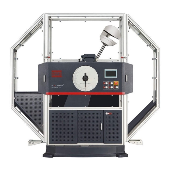
Overview Overview Serial Item Description Mainframe and shield of The pendulum impact tester is used for testing the MTS E22 series impact resistance of testing materials. Control box Control box can set the testing parameters, calculate data, print testing data and communicate with the software. -
Page 22: Overview Of Mainframe And Shield
Overview of mainframe and shield Overview of mainframe and shield The mainframe includes a large base and standoffs. The pendulum shaft is in simple beam structure, with good stress-bearing capabilities. The rear end of the pendulum shaft is connected to the encoder to precisely measure the angle of pendulum impact. - Page 23 Overview of mainframe and shield ® MTS Exceed 22 Series...
- Page 24 Overview of mainframe and shield Exceed 22 Series Parts Serial Name Description Pendulum hanging/release Driven by an air cylinder, it can hang the pendulum or apparatus release it at the time of impact. ® MTS Exceed 22 Series...
- Page 25 Overview of mainframe and shield Exceed 22 Series Parts Serial Name Description Braking apparatus It can lock and fasten the pendulum into place at any position as a safety and protection measure. In the event that the protective apparatus is opened, the...
- Page 26 Overview of mainframe and shield Exceed 22 Series Parts Serial Name Description Pendulum apparatus The apparatus directly impact the sample, having a round pendulum mass connected to a pendulum shaft, is able to be replaced, and has three kinds of power: 450J, 300J and 150J.
-
Page 27: Electric Coupling Plate
Electric Coupling Plate Electric Coupling Plate The MTS Exceed 22 series metal pendulum impact tester uses 220-240 VAC, 50/60 Hz AC power. Warning: Make sure that the power has been switched off before connecting cables. Pay special attention when connecting cables. Make sure the cables are correctly and solidly connected. - Page 28 Electric Coupling Plate Description of Electric Coupling Plate Port Serial Name Description Power outlet Connected to the power line via this port. Printer Port Connected to the printer via this port. Port for sample Connected to the sample recovery motor via this port. recovery motor Ethernet port Connected to the PC via this port.
-
Page 29: Control Panel
Control panel Control panel Control box can set the testing parameters, calculate, record, store and print testing data, and communicate with the software. Control panel Serial Functions Description Dial Printed with scales of power and angle Pointer Indicates the angle and power Pointer rod After pressing, the pointer can be rotated. -
Page 30: Shield
Shield Shield A MTS Exceed series plastic pendulum tester is equipped with a shield, to effectively separate test areas and offer safety protection. ® MTS Exceed 22 Series... -
Page 31: Examples Of Running Charpy Notch Impact Test
Examples of Running Charpy Notch Impact Test Examples of Running Charpy Notch Impact Test * Overview - - - - - - - - - - - - - - - - - - - - - - - - - - - - - - - - - - - - - - - - - - - - - - - - - - - - - - - - - 32 * Safety Introduction - - - - - - - - - - - - - - - - - - - - - - - - - - - - - - - - - - - - - - - - - - - - - - - - - - 33 * Mounting the Pendulum - - - - - - - - - - - - - - - - - - - - - - - - - - - - - - - - - - - - - - - - - - - - - - 35 * Mounting the Support - - - - - - - - - - - - - - - - - - - - - - - - - - - - - - - - - - - - - - - - - - - - - - - - 36... -
Page 32: Overview
Overview Overview This chapter explains how to run a typical Charpy impact test using the typical system in the Introduction 19). The is a simple beam test using impact energy: 450J, execution standard: ISO 148, sample specification:55mm x 10mm x 10mm. Important: During the impact test, the sample may crack or splash. -
Page 33: Safety Introduction
Safety Introduction Safety Introduction Become familiar with the following information: • Impact Zone Warning: The impact zone exists within the swinging range of the pendulum; namely, within the range of the shield. The pendulum is an apparatus that will swing and make impact under the effect of gravity, and therefore possesses a determined impacting force, hitting any object within its swinging range. - Page 34 Safety Introduction • Safety shield The shield is equipped with an access control switch. When any door of the shield is opened, it will stop the test and hold the pendulum in whatever position it was in at the time. ®...
-
Page 35: Mounting The Pendulum
Pressing Block Support Frame The MTS Exceed 22 Series metal pendulum is provided with three kinds of power, namely, 450J, 300J,and 150J.In accordance with the standard requirements, the power consumed for thrusting the sample should be between 10%-80% of the maximum energy of the pendulum. When there are pendulums with several specifications, the pendulum that utilizes a large amount of power is recommended for the test. -
Page 36: Mounting The Support
Span alignment block Impact Blade Pendulum MTS Exceed 22 Series metal pendulum is provided with two kinds of clamps, those being ISO/GB and ASTM. In accordance with the test requirements, install the appropriate clamps and adjust the span. ® MTS Exceed... -
Page 37: Connecting Compressed Air
Connecting Compressed Air Connecting Compressed Air Relief Valve Air Source Inlet Inert the compressed air hose (Dia. 8mm) to the air inlet connector. The equipment is using 0.4-0.8MPa compressed air. Pressure can be adjusted to range value via reducing valve if the compressed air source exceeds the range. ®... -
Page 38: Power On The Mainframe
Power on the Mainframe Power on the Mainframe The power switch position I: power on to start the testing equipment. The power switch position O: power off to turn off the testing equipment ® MTS Exceed 22 Series... -
Page 39: Reset Angle
Reset Angle Reset Angle After the testing equipment is started, wait for 15s, and then enter the main interface of the touch screen and set the language. To ensure the safety and correctness of test data, the equipment should perform clearing action every time it's started. - Page 40 Reset Angle After the clearing action is finished, enter the main interface of the touch screen where you can choose each operation interface to operate. When equipped with automatic sample transmission option, and after the clearing action is finished, enter the main interface of the touch screen where you can choose each operation interface to operate.
-
Page 41: Setting The Parameters
Setting the parameters Setting the parameters Before the test, check that the test parameters are consistent with test conditions; otherwise, it will lead to incorrect test results. Select and enter the Parameter Settings interface: Enter the parameters into the corresponding boxes for such things as sample specifications and pendulum power. - Page 42 Setting the parameters The sample specifications are shown in the following diagram: Sample Width Notch depth Sample length Sample height Tap System Parameters to go into the surface, then enter the energy used by the pendulum and the compensation value of energy loss. ®...
- Page 43 Setting the parameters Tap Pointer Parameters to go into the surface, then select Use Pointer or No Pointer mode: No Pointer: A test method which no pointer is used during the impact test process. In the case where no pointer testing method is used, system will only include the air and bearing induced energy loss and exclude the pointer friction-induced energy loss when calculating the absorbing energy.
-
Page 44: Collecting Pendulum
Collecting Pendulum Collecting Pendulum The principle of the pendulum impact test is to place the notch sample with a specified geometric shape between two supports on the testing equipment, with the notch facing away from the impact. When the sample is hit by the pendulum, the energy absorbed by the sample is measured. Warning: The pendulum is a device that swings and causes impact under the effect of gravity. -
Page 45: Placing Sample
Placing Sample Placing Sample After the pendulum is done moving and is left hanging, open the sliding door of the shield, and place the sample onto the support clamps. The Charpy notch sample needs to be placed on the clamp support with a clamp. -
Page 46: Impact
Impact Impact The impact step is an important step in impact testing. Place the sample, shut the sliding door and touch the Impact icon (or click the Impact button on the control panel, the Impact button on the sliding door); the pendulum will rotate around the shaft to impact the sample under the effect of gravity. -
Page 47: Release The Pendulum
Release the pendulum Release the pendulum After the impact test is finished, the pendulum will return to a hanging state When no more testing is needed, rotate the pendulum to the vertical position. Touch the Release Pendulum icon (or click the button Release Pendulum the control panel), and the equipment will turn the pendulum to the vertical position. -
Page 48: Print Or Export Data
Print or Export Data Print or Export Data In the main surface, tap Test Data to go into the Test Data surface, as shown below: This surface displays 10 most recent test data of the sample test. Next and Previous touch screens will display 30 groups of most recent test data, tap the icon to view different pages of data. - Page 49 Print or Export Data Tap and press Auto/Manual icon to select printing mode. Tap the bottom of the screen and will show a corresponding icon. Auto Print Mode: Test data will be printed after each test is completed. Press Pring Average Value if you need to print average value.
-
Page 50: Sample Loading On The Sample Holder
Sample Loading on the Sample Holder Sample Loading on the Sample Holder Wipe up the Sample Align the notch with the set-square in the sample holder, place enough number of samples and fasten down the pressing plate of the holder. Sample Specification Name Nominal Size/mm... -
Page 51: Placing The Sample Holder
Sample Loading on the Sample Holder Sample Screw Set-square Adjust the holder according to different sample specifications In case of different types of sample specifications, the set-square on the holder shall be adjusted as figure above. Loosen the locking bolts on the set-square, adjust the distance between set-square and sample to 1.5mm, then fasten the bolts. -
Page 52: Placing The Sample Holder
Placing the Sample Holder Placing the Sample Holder Place the sample on the holder and place the holder in a fixed position. ★ NOTE: Scales are on the front of the holder, the two location holes on the bottom of which shall match the two location pins on the base. -
Page 53: Automatic Sample Transporting
Automatic Sample Transporting Automatic Sample Transporting Tap Automatic Transmission to enter Sample Transmission surface, as shown below: Tap the blank of total loaded samples, enter total number of samples required in the cooling chamber, then tap Sample Loading icon. Specified number of samples on the holder will be transmitted into the cooling chamber. -
Page 54: Temperature Control
Temperature Control Temperature Control Tap Temperature Control in the main surface to enter the temperature surface , and will display in the touch screen. Warning: Sample remains a relatively low temperature during the low-temperature test. DO NOT touch the sample and cooling agent circulation pipe with your limbs, or it may result in cold injury. - Page 55 Temperature Control Tap the blank and enter relevant data. ★ NOTE: Such parameters are pre-set by the time of delivery, and shall not be changed at will. Otherwise it will affect the control of temperature. ★ NOTE: When the equipment is running under low temperature, and cooling pipe remains a low temperature.
- Page 56 Temperature Control Parameters Description(Fig 1 below shows how it works) Set Temperature Temperature Required Output amplitude ranging from the Temperature over-shoot endpoint after the switched temperature difference and Temperature I The second switched temperature difference value next to the P value output. Take - 100 ℃...
- Page 57 Temperature Control ® MTS Exceed 22 Series...
-
Page 58: Test Running
Test Running Test Running When samples are placed on the holder, you can perform sample loading, temperature setting, sample transmission impact other than regular operations on mainframe control surface. Actual Temp.: This value is the current temperature in the cooling chamber; Set Temp.: Tap on the blank and enter test temperature required. -
Page 59: Commissioning Status
Commissioning Status Commissioning Status Rotate commissioning status selection switch key on the control panel to select commissioning status of the equipment. The equipment is under commissioning status when the switch key is turned to horizontal position. A password window will pop up in the touch screen. Tap the blank and enter password 3499 to enter the commissioning surface. - Page 60 Commissioning Status ® MTS Exceed 22 Series...
-
Page 61: Calibration
Calibration Calibration * Overview - - - - - - - - - - - - - - - - - - - - - - - - - - - - - - - - - - - - - - - - - - - - - - - - - - - - - - - - - 62 * Measuring of energy loss due to bearing friction and air resistance - - - - - - - - - - - - - - - - 63 * Measuring of energy loss due to pointer friction - - - - - - - - - - - - - - - - - - - - - - - - - - - - - - 64 * Calibration of Temperature Sensor - - - - - - - - - - - - - - - - - - - - - - - - - - - - - - - - - - - - - - - 66... -
Page 62: Overview
Overview Overview The testing equipment loses power when impacting, including energy loss P due to pointer friction, as well as the energy loss P' due to bearing friction and air resistance. In order to test the performance, it is necessary to check the tester to calculate the energy loss. When equipped with automatic sample transmission option, it is necessary to calibrate the temperature sensor regularly to ensure the accuracy of testing temperature. -
Page 63: Measuring Of Energy Loss Due To Bearing Friction And Air Resistance
Overview Measuring of energy loss due to bearing friction and air resistance Tap Parameter Settings in the main interface to enter the parameter setting interface, then tap System Parameter to enter the system parameter interface, as the following figure: In the System Parameter interface, you can perform free pendulum energy loss calculation and setting of energy loss compensation, pendulum power, second collecting pendulum impulsion and gravity acceleration. -
Page 64: Measuring Of Energy Loss Due To Pointer Friction
Overview Measuring of energy loss due to pointer friction Tap Parameter Settings in the main interface to enter the parameter setting interface, then tap Pointer Parameter to enter the pointer parameter interface, as the following figure: ® MTS Exceed 22 Series... - Page 65 Overview After taking the pendulum, set the pointer to the maximum energy dial energy level. Press Start, and the equipment will begin to test the energy loss caused by pointer friction. After the equipment completes the impact, record the absorbed energy. Do not set the pointer. The equipment will perform a second impact and record the energy absorbed.
-
Page 66: Calibration Of Temperature Sensor
Overview Calibration of Temperature Sensor When equipped with automatic sample transmission option, it is necessary to calibrate the temperature sensor regularly to ensure the accuracy of testing temperature. Clean the cooling chamber after long-term using. Press the icon, and loosen the locking bolt, remove parts such as the shield, insulating layer, cover plate etc. When calibrating temperature, thread the calibrated temperature sensor into the cooling room through the sample holder opening, and stick a tape in the middle of the sample passage in the cooling chamber, then fasten the parts (such as the shield) and start the temperature calibration. -
Page 67: Maintenance
Maintenance Maintenance * Routine Maintenance List - - - - - - - - - - - - - - - - - - - - - - - - - - - - - - - - - - - - - - - - - - - - - 68 ®... -
Page 68: Routine Maintenance List
Maintenance Routine Maintenance List Recommended Services Rated 8 hours of operation per day Daily Weekly Yearly Operation-Hours 2000 Clean work area/equipment surfaces Check energy losses Check whether the bearing jaw is in the middle Check cables/connections System Check Check/adjust initial angle Check the brake performance Check cable connections System Inspection... - Page 69 Maintenance There are no customer-usable components on MTS Exceed system. Maintenance includes cleaning of main unit and working areas, routine inspections, and main unit regular calibration. WARNING: Be careful not to spill cleaning agents on the equipment. The equipment may be short-circuited and damaged if you accidentally spill cleaning agents or fluids on electronic components.
-
Page 71: Troubleshooting
Troubleshooting Troubleshooting * Troubleshooting - - - - - - - - - - - - - - - - - - - - - - - - - - - - - - - - - - - - - - - - - - - - - - - - - - - - 72 ®... -
Page 72: Troubleshooting
Troubleshooting Troubleshooting The table below describes some of the basic troubleshooting problems and solutions. Troubleshooting of Common Faults (part 1 of 2) Fault Description Solution The touch screen is not on or • Check whether power cord is plugged in. displays incorrectly when the •... - Page 73 Troubleshooting Troubleshooting of Common Faults (part 2 of 2) Friction exceeds tolerance • This may also be caused by dirt in or damages of the ball bearing. In this case, remove the bearing and then clean or replace it. Spray a small amount of WD40 versatile rust- inhibiting lubricant before installation.
-
Page 75: Stopping Use
Stopping Use Stopping Use * Stopping Use - - - - - - - - - - - - - - - - - - - - - - - - - - - - - - - - - - - - - - - - - - - - - - - - - - - - - 76 ®... - Page 76 Stopping Use Stopping Use If you are about to move or no longer using the impact tester, please do follow the procedures below: 1. Remove pendulum. 2. Power off the system and cut off the air source. 3. After system's electrical devices are powered off, switch off the main power and disconnect all cables and air source.
- Page 78 MTS Systems Corporation http://www.mts.com/en/Global/index.asp ISO 9001 Certified QMS...
Need help?
Do you have a question about the Exceed 22 Series and is the answer not in the manual?
Questions and answers