
Related Manuals for MTS Systems 318 Series


Summary of Contents for MTS Systems 318 Series
- Page 1 be certain. 318 Load Unit Product Information Model 318.10 Model 318.25 Model 318.50 100-183-837 B...
- Page 2 © 2007, 2009 MTS Systems Corporation. All rights reserved. Trademark information MTS is a registered trademark of MTS Systems Corporation within the United States. This trademark may be protected in other countries. Molykote is a registered trademark of Dow Chemical Corporation. All other trademarks or service marks are property of their respective owners.
-
Page 3: Table Of Contents
Contents Technical Support 7 How to Get Technical Support 7 Before You Contact MTS 7 If You Contact MTS by Phone 9 Problem Submittal Form in MTS Manuals 10 Preface 11 Before You Begin 11 Conventions 12 Documentation Conventions 12 Introduction 15 Load Unit: Overview 15 318 Load Unit: Component Identification 17... - Page 4 Installation 47 318 Load Unit: Unpack Upright Configuration 47 318 Load Unit: Unpack Horizontal Configuration 49 318 Load Unit: Connect Cables 54 318 Load Unit: Connect Hydraulics 56 318 Load Unit: Unlock the Crosshead 56 Operation 59 Load Unit: Operation Preface 59 318 Load Unit: Control Module 60 318 Load Unit: Crush Point Hazards 62 318 Load Unit: Specimen Installation 62...
- Page 5 8 Hours/Daily 108 40 Hours/Weekly 109 80 Hours/Biweekly 110 500 Hours: Crosshead and Frame 111 500 Hours: Actuator 112 500 Hours: HSM 113 500 Hours: Hoses and Cables 114 500 Hours: Overall Complete System 115 500 Hours: Grips 116 1000 Hours 117 2000 Hours: Annual Maintenance 118 318 Load Unit Contents...
- Page 6 Contents 318 Load Unit...
-
Page 7: Technical Support
Technical Support How to Get Technical Support Start with your The manuals supplied by MTS provide most of the information you need to use manuals and maintain your equipment. If your equipment includes MTS software, look for online help and README files that contain additional product information. If you cannot find answers to your technical questions from these sources, you can use the internet, e-mail, telephone, or fax to contact MTS for assistance. - Page 8 Know information from If you have contacted MTS about this problem before, we can recall your file. prior technical You will need to tell us the: assistance • MTS notification number • Name of the person who helped you Identify the problem Describe the problem you are experiencing and know the answers to the following questions: •...
-
Page 9: If You Contact Mts By Phone
If You Contact MTS by Phone Your call will be registered by a Call Center agent if you are calling within the United States or Canada. Before connecting you with a technical support specialist, the agent will ask you for your site number, name, company, company address, and the phone number where you can normally be reached. -
Page 10: Problem Submittal Form In Mts Manuals
Problem Submittal Form in MTS Manuals Use the Problem Submittal Form to communicate problems you are experiencing with your MTS software, hardware, manuals, or service which have not been resolved to your satisfaction through the technical support process. This form includes check boxes that allow you to indicate the urgency of your problem and your expectation of an acceptable response time. -
Page 11: Preface
Preface Before You Begin Safety first! Before you attempt to use your MTS product or system, read and understand the Safety manual and any other safety information provided with your system. Improper installation, operation, or maintenance of MTS equipment in your test facility can result in hazardous conditions that can cause severe personal injury or death and damage to your equipment and specimen. -
Page 12: Conventions
Conventions Conventions Documentation Conventions The following paragraphs describe some of the conventions that are used in your MTS manuals. Hazard conventions As necessary, hazard notices may be embedded in this manual. These notices contain safety information that is specific to the task to be performed. Hazard notices immediately precede the step or procedure that may lead to an associated hazard. - Page 13 Conventions Hypertext links The electronic document has many hypertext links displayed in a blue font. All blue words in the body text, along with all contents entries and index page numbers, are hypertext links. When you click a hypertext link, the application jumps to the corresponding topic.
- Page 14 Conventions Preface 318 Load Unit...
-
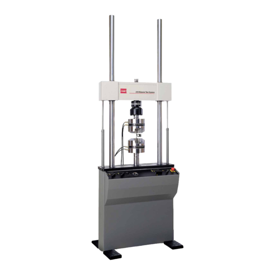
Page 15: Introduction
Introduction Load Unit: Overview The Load Unit is the primary structure for most materials testing. It is a stand- alone testing unit. The load unit consists of the load frame plus additional parts, such as hydraulic crosshead lifts and control modules. Load units come in different sizes and shapes. - Page 16 What you MTS Systems Corporation assumes that you know how to use your controller. need to know See the appropriate manual for information about performing any controller- related step in this manual’s procedures. You are expected to know how to perform the following procedures: •...
-
Page 17: Load Unit: Component Identification
318 Load Unit: Component Identification Component Descriptions OMPONENT ESCRIPTION Crosshead Moves the up and down the column to accommodate different sized specimens and fixtures. The crosshead is stiff and light weight; it is one end of the force train. Crosshead locks Clamps the crosshead to the columns. -
Page 18: Load Unit: Component Description
Component Descriptions OMPONENT ESCRIPTION Control panel The Emergency Stop button is standard; the other controls are optional. Grip Clamps and unclamps the hydraulically controlled grips during specimen controls installation and removal. Controls the crosshead lifts to raise and lower the crosshead hydraulically. Crosshea d lift Removes hydraulic pressure from the load unit and issues an interlock signal... - Page 19 Load frame The load frame is the basic structure which provides the reaction mass for the force train. The base of the load frame is one end of the reaction mass and the crosshead is the other end of the reaction mass. Installing a specimen and other fixtures or components between the load unit base and the crosshead create a force train.
-
Page 20: Load Unit: Specifications
69 MPa (10,000 psi) to accommodate a variety of grips manufactured by MTS Systems Corporation. A front panel control allows the grip pressure to be adjusted within the factory setting. A rate control sets how fast the grips open and close. - Page 21 ARAMETER PECIFICATION approximate minimum weight Weight Base mount 500 kg (1100 lb) 318.10 960 kg (2120 lb) 318.25 1900 kg (4200 lb) 318.50 Crosshead mount 555 kg (1225 lb) 318.10 1065 kg (2345 lb) 318.25 2100 kg (4625 lb) 318.50 The weight specification is for lifting and moving purposes.
- Page 22 For the most accurate high frequency test results, use a load unit with a fatigue rating that is larger than its actuator’s force rating. For example, a Model 318.25 Load Unit with a 55 kip fatigue rating and a 22 kip actuator will have smaller deflections than a Model 318.10 Load Unit with a 22 kip fatigue rating and a 22 kip actuator.
- Page 23 318.10 318.25 318.50 EFLECTIONS ODEL ODEL ODEL N/22 N/55 N/110 A - D overall frame 0.38 mm 0.015 in 0.58 mm 0.023 in 0.66 mm 0.026 in Spring rates 2.6 x 10 4.3 x 10 7.5 x 10 (1.5 x 10 lb/in) (2.4 x 10 lb/in)
-
Page 24: Series 661 Force Transducer: Specifications
Series 661 Force Transducer: Specifications The force transducer used with this system is a Series 661 Force Transducer. The following are the specifications for the force transducers. ARAMETER PECIFICATION Maximum excitation voltage 15 V DC Bridge resistance 350 ¾ Maximum crosstalk 1.0% of full scale torsional to load Hysteresis 0.08% of full scale (250 N–2.5 kN) - Page 25 ODEL APACITY EIGHT HREAD 661.20-01 25 kN M27 x 2.0 mm x 31.7 mm 9.75 kg (5.5 kip) (1 - 14 UNS-3B x 1.25 in) (21.5 lb) 661.20-02 50 kN M27 x 2.0 mm x 31.7 mm 9.75 kg (11 kip) (1 - 14 UNS-3B x 1.25 in) (21.5 lb) 661.20-03...
-
Page 26: Load Unit: Dimensions
318 Load Unit: Dimensions 318.10B Load Unit Dimensions Introduction 318 Load Unit... - Page 27 318.25B Load Unit Dimensions 318 Load Unit Introduction...
- Page 28 318.50B Load Unit Dimensions Introduction 318 Load Unit...
- Page 29 318.10B Load Unit with Crosshead Actuator Dimensions 318 Load Unit Introduction...
- Page 30 318.25B Load Unit with Crosshead Actuator Dimensions Introduction 318 Load Unit...
- Page 31 318.50B Load Unit with Crosshead Actuator Dimensions 318 Load Unit Introduction...
- Page 32 Introduction 318 Load Unit...
-
Page 33: Safety
Safety General Safety Practices This section provides information about safety issues that pertain to servohydraulic systems in general. These issues include statements to the intended use and foreseeable misuse of the system, the hazard zone, definition for the graphical hazard labeling that is affixed to your product, and other (more general) safety information that relates to the high-pressure and high- performance characteristics of MTS servohydraulic systems. -
Page 34: Safety Practices Before System Operation
If you have system related responsibilities (that is, if you are an operator, service engineer, or maintenance person), you should study safety information carefully before you attempt to perform any test system procedure. You should receive training on this system or a similar system to ensure a thorough knowledge of your equipment and the safety issues that are associated with its use. - Page 35 Locate and read Find, read, and follow the hazard placard instructions located on the equipment. hazard placards/labels These placards are placed strategically on the equipment to call attention to areas such as known crush points and electrical voltage hazards. Locate Lockout/tagout Know where the lockout/tagout point is for all of the supply energies associated points with your system.
- Page 36 Keep bystanders Keep bystanders at a safe distance from all equipment. Never allow bystanders to safely away touch specimens or equipment while the test is running. Wear proper clothing Do not wear neckties, shop aprons, loose clothing or jewelry, or long hair that could get caught in equipment and result in an injury.
- Page 37 Observe the following safety practices when you work with high-pressure air or gases: • When you charge an accumulator, follow all the charging instructions provided in the appropriate product information manuals. When precharging accumulators, properly identify the type of gas to be used and the type of accumulator to be precharged.
- Page 38 Do not exceed the For standard MTS systems, ensure that hydraulic supply pressure is limited to a Maximum Supply maximum 21 MPa (3000 psi). If you system has a custom application that...
-
Page 39: Safety Practices While The System Is In Operation
Provide adequate Ensure adequate lighting to minimize the chance of operation errors, equipment lighting damage, and personal injury. You need to see what you are doing. Provide means to Make sure you can access system components that might be out of reach while access out-of-reach standing on the floor. - Page 40 Do not disturb sensors Do not bump, wiggle, adjust, disconnect, or otherwise disturb a sensor (such as an accelerometer or extensometer) or its connecting cable when hydraulic pressure is applied. Ensure secure cables Do not change any cable connections when electrical power or hydraulic pressure is applied.
-
Page 41: Hazard Icons
Hazard Icons Following are the hazard icons used on the MTS products. ESCRIPTION Moving parts; pinch points. Keep clear of areas noted with this label High pressure fluid or gasses. Do not tamper with fittings or hoses. Possible explosive or flying debris. Wear appropriate protection such as safety goggles and hearing protection. -
Page 42: Load Unit: Hazard Labels
ESCRIPTION Alternate read the manuals or instructions. Become familiar with safety information. Also become familiar with operating and maintenance information. Hot surfaces. Possible burn hazard. Wear personal protective equipment such as gloves when working near hot surfaces. Object is heavy. Requires more that one person to lift and move. - Page 43 Base Assembly View A-A UMBER ESCRIPTION 045-384-101 Warning. High force moving parts. Can cause severe injury or equipment damage. Stay clear and use eye protection while test is in progress. Read instructions before operating or servicing. 037-588-901 Identification label. Includes model number, part number, serial number, force capacity, and manufacture date.
- Page 44 Cylinder Assembly UMBER ESCRIPTION 037-588-801 Identification label. Includes model number, serial number, assembly number, force, effective date, static stroke, dyn stroke, and hydrostatic bearing. 038-202-801 Warning. Subjecting this equipment to working pressure above 3000 psi (21 MPa) can result in component rupture and injury to personnel.
-
Page 45: Load Unit: Crush Point Hazards
318 Load Unit: Crush Point Hazards It is important to stay clear of any potential crush points when the system is operating. Know where the crush points are in your system and protect yourself and others from those crush points with appropriate safety devices. The following paragraphs describe crush points and precautions to take while working around crush points. - Page 46 Safety 318 Load Unit...
-
Page 47: Installation
Installation 318 Load Unit: Unpack Upright Configuration 1. Unpack the load unit. A. Remove the shipping container (if used). Remove the protective wrapping around the columns. Use a clean cloth to wipe the columns clean. Note The load unit can be moved by a fork lift as long as the load unit is attached to its pallet. - Page 48 2. Inspect the load unit for shipping damage. Look for the following: • Scratches in the load unit or lift cylinder columns • Damaged electrical connections • Damaged hydraulic connections • Dents and other structural damage • Torn, kinked, or breaking hoses Report any damage found to both the carrier and MTS.
-
Page 49: Load Unit: Unpack Horizontal Configuration
WARNING Airmounts can be overinflated and then explode. You can be seriously hurt if an airmount explodes, sending fragments flying. Do not overinflate the airmounts. 318 Load Unit: Unpack Horizontal Configuration Prerequisites The load unit is shipped horizontally on a wooden pallet. You will need the following equipment to unpack the load unit: •... - Page 50 WARNING The load unit is extremely heavy. The weight of the load unit can seriously hurt you and damage your load unit. Do not allow the load unit to drop or topple. Observe the following precautions: • Ensure that your chains, slings, and crane have a working capacity greater than the load unit’s weight.
- Page 51 CAUTION Scratches in the load unit columns can affect how the crosshead performs. Chains will scratch the columns. Use slings to lift the load unit from its pallet. Keep the base steady Slings at center of gravity Slide Rubber mat Wooden blocks Removing the Load Unit from Its Pallet 318 Load Unit...
- Page 52 2. Inspect the load unit for shipping damage. Look for the following: • Scratches in the load unit or lift cylinder columns • Damaged electrical connections • Damaged hydraulic connections • Dents and other structural damage • Torn, kinked, or breaking hoses Report any damage found to both the carrier and MTS.
- Page 53 Once the load unit is upright, raise it slightly so that the pallet can be removed. Crane travel ° maximum Bringing the Load Unit Upright Before you move the load unit, that: • The floor where the load unit will sit can bear its weight. •...
-
Page 54: Load Unit: Connect Cables
• If your load unit has airmounts, inflate each airmount in 5 mm (0.20 in) increments to level the load unit. – Check the airmounts’ pressures often to ensure that they do not exceed 0.55 MPa (80 psi). – Check the airmounts’ inflated heights to ensure that they are all between 83 and 88 mm (3.25 and 3.5 in). - Page 55 Prerequisite You must have either a cable assembly drawing of your test system, or you must know the system controller well enough to determine each type of cable connection. Ê Ë Ì Í Î Ï 1. The force transducer is connected to a DC conditioner in the controller. 2.
-
Page 56: Load Unit: Connect Hydraulics
7. Return to the installation procedure. 318 Load Unit: Connect Hydraulics The procedure describes how to connect the load unit to the hydraulic power source. The load unit may be connected directly to the hydraulic power unit (also called HPU), to hydraulic plumbing in the workplace, or through a hydraulic service manifold. - Page 57 2. Fully loosen the manual crosshead locking bolts in the order shown in the following figure. 318.10 136 N·m (100 lbf·ft) 318.25 271 N·m (200 lbf·ft) 318.50 271 N·m (200 lbf·ft) Loosening the Manual Lock Bolts 3. Cycle the lock control to unclamp, and then reclamp, the crosshead. 4.
- Page 58 Installation 318 Load Unit...
-
Page 59: Operation
Operation Load Unit: Operation Preface This section describes the load unit controls, crush point hazards, and procedures performed during the normal, day-to-day operation of the load unit. Application note Special considerations must be followed when using low force transducers in a high force systems. -
Page 60: Load Unit: Control Module
318 Load Unit: Control Module The controls for the 318 Load Unit are located on a module mounted to the front of the load unit. Crosshead Lift / Lock Control Emergency Stop Hydraulic Grip Control Pressure Rate Series 318 Load Unit Controls ONTROL ESCRIPTION Hydraulic Grip Controls... - Page 61 Series 318 Load Unit Controls ONTROL ESCRIPTION Crosshead Lift/Lock Controls the movement and clamping of the crosshead. The left handle raises Controls and lowers the crosshead. The right handle locks and unlocks the crosshead. The crosshead must not be moved while it is clamped. Unlock Lock Stop...
-
Page 62: Load Unit: Crush Point Hazards
318 Load Unit: Crush Point Hazards It is important to stay clear of any potential crush points when the system is operating. Know where the crush points are in your system and protect yourself and others from those crush points with appropriate safety devices. The following paragraphs describe crush points and precautions to take while working around crush points. - Page 63 Prerequisite You must have the necessary grips and/or fixturing installed. You must also have the controller set up to control the actuator movement, and you must have a test program defined. CAUTION When changing hydraulic grips, make sure you cap or plug the hydraulic hoses when removed to prevent oil spillage.
- Page 64 CAUTION The crosshead can slowly drift down the columns if the locks are turned off and when hydraulic pressure is turned off. The crosshead can damage any test fixtures, grips, and specimen in its path. Unlock the crosshead only to reposition it. Always lock the crosshead after you have repositioned it, and never leave the crosshead unlocked.
-
Page 65: Load Unit: Position The Crosshead Hydraulically
CAUTION Before testing, ensure both grips are clamped and the specimen is secure. An insufficiently gripped specimen can cause specimen damage, equipment damage and the possibility of specimen fragmentation. 318 Load Unit: Position the Crosshead Hydraulically 1. This step pressurizes the lift actuators. The crosshead might have shifted position while hydraulic pressure was turned off. -
Page 66: Load Unit: Position The Crosshead Manually
4. Use the Crosshead Lift/Lock Controls to clamp the crosshead to its current position. Wait 30 seconds for the locks to fully clamp the columns. 318 Load Unit: Position the Crosshead Manually This procedure describes how to position a crosshead for a load unit with no hydraulic crosshead lifts or locks. - Page 67 3. Remove the covers on the ends of the crosshead. The crosshead covers must be removed to access the manual locking bolts and to clean and lubricate the bolts. Six 1/4-20 screws (three top, three bottom) on each cover need 5/32 hex (not included).
- Page 68 WARNING The crosshead is very heavy. A dropping crosshead can crush hands, damage grips, and smash specimens. Observe the following precautions to reduce the possibility of unexpected crosshead movement: • Ensure that the crosshead is locked. • The overhead crane and lifting chains must be able to support the weight of the crosshead (see the Crosshead Weight table below).
-
Page 69: Load Unit: Adjust The Grips' Clamp Rate
318.25 20 N·m 244 N·m 271 N·m 271 N·m (15 lbf·ft) (180 lbf·ft) (200 lbf·ft) (200 lbf·ft) 318.50 20 N·m 244 N·m 271 N·m 271 N·m (15 lbf·ft) (180 lbf·ft) (200 lbf·ft) (200 lbf·ft) This step ensures uniform tightness. 318 Load Unit: Adjust the Grips’ Clamp Rate The clamp rate determines how fast the grip can clamp a specimen. -
Page 70: Load Unit: Adjust The Grips' Clamp Force
Note The Pressure control can adjust the grip pressure up to the maximum output pressure setting (which is initially set by MTS Systems Corporation). 1. Ensure that both the upper grip control and lower grip control are in the unclamp position. - Page 71 5. Adjust the Pressure control for the desired hydraulic pressure. Pressure Less More 6. If you exceed the desired pressure setting, adjust the Pressure control counterclockwise 1/2 turn. If pressure setting exceeds 20 MPa (3000 psi) cycle (clamp and unclamp) one of the grips. Return to Step 5. 318 Load Unit Operation...
- Page 72 Operation 318 Load Unit...
-
Page 73: Maintenance
Maintenance 318 Load Unit: Maintenance Intervals 318 Load Unit: Daily Inspections 318 Load Unit: Clean the Columns 318 Load Unit: Prevent Rust 318 Load Unit: Maintain Airmount Pressures 318 Load Unit: Bleed the Hydraulic Lift Cylinders 318 Load Unit: Adjust the Hydraulic Locks 318 Load Unit: Lubricate the Crosshead Locking Bolts 318 Load Unit: Align the Force Transducer 111 Accumulator: Maintenance Overview... -
Page 74: Routine Maintenance Overview Checklist
Routine Maintenance Overview Checklist Routine Maintenance Overview Checklist Recommended service to be performed at each running time interval noted ALENDAR IME USING HOUR UNNING IME RATE AILY EEKLY IWEEKLY NNUALLY PER DAY 1000 1,500 2,000 UNNING OURS Check Actuator Platen Area to be Clean Monitor Filter Indicators Check Hoses/Cables/Connectors Check Crosshead/Lifts/Supports... - Page 75 Routine Maintenance Overview Checklist Recommended service to be performed at each running time interval noted ALENDAR IME USING HOUR UNNING IME RATE AILY EEKLY IWEEKLY NNUALLY PER DAY 1000 1,500 2,000 UNNING OURS Actuator Area is Dry Actuator Platen Area is Clean Piston Rod Wear is Acceptable Bionix Lubricate Axial/Torsional Spline (75-100 hrs)
- Page 76 Routine Maintenance Overview Checklist Recommended service to be performed at each running time interval noted ALENDAR IME USING HOUR UNNING IME RATE AILY EEKLY IWEEKLY NNUALLY PER DAY 1000 1,500 2,000 UNNING OURS Response to Full Stroke Waveform, Visual and Audible Valve Balance check displacement control Valve Dither Response Grips...
-
Page 77: Load Unit: Maintenance Intervals
Routine Maintenance Overview Checklist 318 Load Unit: Maintenance Intervals The following table lists the recommended interval for each of these procedures. HAT TO HEN TO Make daily inspections Before the start of each day’s testing. When the columns become greasy Clean the load unit columns or dirty. -
Page 78: Load Unit: Daily Inspections
Routine Maintenance Overview Checklist 318 Load Unit: Daily Inspections Before the start of each day’s testing, do a quick inspection of your load unit. Following are typical things that should be checked daily: • Ensure that there are no leaks from lifts or locks. •... -
Page 79: Load Unit: Prevent Rust
Routine Maintenance Overview Checklist 318 Load Unit: Prevent Rust Where you operate the load unit determines how often you take rust prevention measures. Humid and corrosive environments require more prevention. Recommended • #1 grade kerosene supplies: • Silicone spray • 000 emery cloth •... -
Page 80: Load Unit: Maintain Airmount Pressures
Routine Maintenance Overview Checklist 318 Load Unit: Maintain Airmount Pressures Optional inflatable airmounts reduce vibration and noise. They are installed under the feet of the load unit. Inflation pressures must be maintained to both level and isolate the load unit. WARNING Airmounts can be overinflated and then explode. -
Page 81: Load Unit: Bleed The Hydraulic Lift Cylinders
Routine Maintenance Overview Checklist 318 Load Unit: Bleed the Hydraulic Lift Cylinders Bleed both hydraulic lift cylinders whenever the crosshead does not move smoothly. Also bleed them whenever the sealed side of the hydraulic system has been opened to air. The following figure shows the location of the bleed ports for the two types of lifts commonly used. - Page 82 Routine Maintenance Overview Checklist CAUTION The crosshead can slowly drift down the columns if the locks are turned off and the hydraulic pressure is turned off. The crosshead can damage any test fixtures, grips, and specimen in its path. Unlock the crosshead only to reposition it. Always lock the crosshead after you have repositioned it, and never leave the crosshead unlocked.
-
Page 83: Load Unit: Adjust The Hydraulic Locks
Routine Maintenance Overview Checklist 7. Briefly turn the Lift Control to the lift crosshead position to pressurize the lift cylinders. Then return it to the stop crosshead position. No bubbles Close 8. Shut the bleed port when bubble-free fluid begins oozing out. If necessary, again pressurize the lift cylinders to force all the air out. - Page 84 Routine Maintenance Overview Checklist Turn on high hydraulic pressure. If there is a specimen in the load unit, remove it. D. Move the crosshead to a comfortable working height. CAUTION The crosshead can slowly drift down the columns if the locks are turned off and the hydraulic pressure is turned off.
- Page 85 Routine Maintenance Overview Checklist 4. Use the Lock Control to lock the crosshead. Then torque the manual crosshead locking bolts in the order shown in the following illustration. 5. Turn off hydraulic pressure. 6. Use the Lock Control to the unlock crosshead position to remove pressure from the hydraulic locks.
-
Page 86: Load Unit: Lubricate The Crosshead Locking Bolts
Routine Maintenance Overview Checklist 14. Move the crosshead, locking and unlocking it, to check for smooth operation. 318 Load Unit: Lubricate the Crosshead Locking Bolts Lubricate the locking bolts in a manually locked crosshead whenever they begin to be hard to tighten or sticky when loosened. 1. -
Page 87: Load Unit: Align The Force Transducer
Routine Maintenance Overview Checklist 318 Load Unit: Align the Force Transducer This section describes how to align a force transducer with the load unit actuator. The load units shown may vary from what you may have. The 318.10 and some 318.25 Load Units come with two types of transducer mounting hardware. - Page 88 Routine Maintenance Overview Checklist A. Position the actuator at midstroke. Set and enable the test controller’s upper and lower limit detect interlocks to limit the actuator’s movement to 2 mm (0.10 in) in each direction. Move the crosshead so there is about 360 mm (14 in) between the top of the actuator and the bottom of the force transducer.
- Page 89 Routine Maintenance Overview Checklist 3. Check the alignment. In this step, you check the alignment between the force transducer and the actuator. Read along the edge Zero Zero Read along the edge 360° 360° Attaching and Zeroing the Indicator A. Attach the dial indicator to the actuator. On a low profile force transducer, adjust the indicator to take the reading along the edge of the loading surface.
- Page 90 Routine Maintenance Overview Checklist 4. Prepare the force transducer. Depending on the type of force transducer you have, perform one of the following procedures: • Hex nut mount only • Preloader collar mount only Hex nut mount only The following procedure applies only to force transducers that are mounted to the crosshead with a single hex nut.
- Page 91 Routine Maintenance Overview Checklist Preloader collar mount The following procedure applies only to force transducers that are mounted only to the crosshead using a preload collar. Loosen the six jack bolts or setscrews in 1/4 turn steps to remove most of the tension on the preloader collar, following a standard crisscross torque sequence.
- Page 92 Routine Maintenance Overview Checklist Tighten to 5% of the torque recorded on the identification plate. Hex nut—Tighten the nut to 5% of the final torque shown on the identification plate. Preloader collar—Tighten the jackbolts or setscrews to 5% of the final torque shown on the identification plate.
-
Page 93: Accumulator: Maintenance Overview
Routine Maintenance Overview Checklist Turn the load unit’s hydraulic pressure to off. Unscrew/Tighten Anti-Rotate Actuator—Tightening the Cap Screws D. If your load unit has an antirotate actuator, tighten the four antirotate cap screws to a torque listed in the following table. (The actuator force rating is stated on an identification plate at the rear of the load unit.) CTUATOR ORCE... -
Page 94: Accumulator: Check And Change Precharge Pressure
Routine Maintenance Overview Checklist Use the following guidelines to determine when maintenance is required. • Check the precharge pressure at periodic intervals. The length of time between checks depends on how the system is used. Some factors to consider when establishing this time interval are operating frequency, displacement, and duration. - Page 95 Routine Maintenance Overview Checklist Prerequisite To prepare the accumulator for precharge check: WARNING Accumulators are pressurized devices. Pressurized accumulators and their parts can become lethal projectiles if disassembled and can cause death to persons and/or damage to equipment. Do not remove an accumulator that is pressurized. Completely remove hydraulic pressure and discharge the accumulator before any parts, except the protective cover and valve stem cap, are removed.
- Page 96 Routine Maintenance Overview Checklist 2. With an open-end wrench, turn the locknut counterclockwise on the accumulator valve assembly to open the valve. Read the pressure on either the high or low accumulator charging kit pressure gage. • If the pressure reading is other than the required pressure level recorded on the accumulator, continue with the next subsection, “Change the Precharge Pressure”.
- Page 97 Routine Maintenance Overview Checklist WARNING Mixing gases can produce unpredictable results. Do not use another gas to precharge an accumulator. Use only dry nitrogen gas to precharge accumulators. 3. Connect the nitrogen supply hose from the supply bottle pressure regulator output to the input check valve on the charging kit.
-
Page 98: Actuator: Maintenance
Routine Maintenance Overview Checklist 244 Actuator: Maintenance The 244 Actuator is designed for extended periods of operation without extensive maintenance requirements. A summary of the routine maintenance procedures is listed below: Weekly Clean exposed areas of the actuator piston rod with a clean, dry, lint free rag. If the actuator is continually exposed to a dirty operating environment, clean the piston rod on a daily basis. - Page 99 Contaminated hydraulic fluid can cause premature wear of the hydraulic components in your system. Do not mix different brands of hydraulic fluid. MTS Systems Corporation recommends using Mobil DTE-25 or Shell Tellus 46 AW hydraulic fluid. The filter element should be replaced whenever: •...
-
Page 100: Servovalve: Maintenance Overview
You must have a filter kit that contains the necessary filter element replacement parts. The filter for the Series 252.3x Servovalves is MTS part number 032-844- 101. Contact MTS Systems Corporation for the filter for the revision G Series 252.2x/4x Servovalves... - Page 101 Routine Maintenance Overview Checklist Procedure To replace the filter element, perform the following procedure. Care should be exercised to prevent dirt or other contaminants from entering the servovalve body, filter passages, or manifold/actuator ports. Refer to the following figure during the procedure. Socket Head Screws (4) Filter Cover...
-
Page 102: Servovalve: Adjust The Mechanical Null
Prerequisites MTS Systems Corporation recommends that you read this procedure before attempting to adjust the mechanical null. The mechanical null adjustment is quite sensitive, and you should be familiar with the hazards that can be encountered when performing the procedure. - Page 103 Routine Maintenance Overview Checklist During the servovalve mechanical null adjustment procedure, the actuator must be able to move through full displacement in either direction without contacting a reaction surface. Valve balance MTS controllers have an electronic mechanical null adjustment called valve adjustments balance.
- Page 104 Routine Maintenance Overview Checklist CAUTION Excessive torquing may shear off the adjustor pin eccentric. Do not apply more than 12 lbf-in. (1.36 N•m) of torquing force to the adjustor pin. If the pin does not turn using very little force, proceed to Step C of this task. Slowly rotate the adjustor pin until the actuator movement is reduced to a minimum, and then go back to Step 2.
- Page 105 Routine Maintenance Overview Checklist Using the offset wrench, loosen (but do not remove) the self-locking nut. Mechanical Null Adjustor Pin H. Turn the adjustor pin until the scribe mark on the adjustor pin is pointing toward the base of the servovalve. Tighten the self-locking nut until 1.13 to 1.36 N·m (10 to 12 lb-in) of torque is needed to turn the adjustor pin, ensuring that the scribe mark remains pointing toward the base of the servovalve.
- Page 106 Routine Maintenance Overview Checklist Maintenance 318 Load Unit...
-
Page 107: Servohydraulic Load Frame Maintenance And Service Logs
Servohydraulic Load Frame Maintenance and Service Logs Contents 8 Hours/Daily 40 Hours/Weekly 80 Hours/Biweekly 500 Hours: Crosshead and Frame 500 Hours: Actuator 500 Hours: HSM 500 Hours: Hoses and Cables 500 Hours: Overall Complete System 500 Hours: Grips 1000 Hours 2000 Hours: Annual Maintenance Servohydraulic Load Frame Maintenance and Service Logs... -
Page 108: Hours/Daily
8 Hours/Daily 8 Hours/Daily 8 Hours/Daily Service Interval Recommendation HECK CTUATOR ONITOR ILTER LATEN REA TO NDICATORS LEAN ERFORMED BY ERFORMNED BY OTES Servohydraulic Load Frame Maintenance and Service Logs... -
Page 109: Hours/Weekly
40 Hours/Weekly 40 Hours/Weekly 40 Hours/Weekly Service Interval Recommendation HECK OSES HECK HECK HECK HECK HECK ABLES ROSSHEAD CTUATOR YDRAULIC ONDITION ONDITION ONNECTORS IFTS UPPORTS ERVICE TO BE TO BE ANIFOLD ERFORMED BY ERFORMNED BY ERFORMNED BY ERFORMNED BY ERFORMNED BY ERFORMNED BY OTES Servohydraulic Load Frame Maintenance and Service Logs... -
Page 110: Hours/Biweekly
80 Hours/Biweekly 80 Hours/Biweekly 80 Hours/Biweekly Service Interval Recommendation IONIX UCRICATE HECK XIAL ORSIONAL CTUATOR (75-100 PLINE ERFORMED BY ERFORMNED BY OTES Servohydraulic Load Frame Maintenance and Service Logs... -
Page 111: Hours: Crosshead And Frame
500 Hours: Crosshead and Frame 500 Hours: Crosshead and Frame 500 Hours Service Interval Recommendation HECK ROSSHEAD OLUMN ROSSHEAD ONDITION IS ONDITION IS OLUMNS ARE BRASIONS ARE IFTS LEAN CCEPTABLE UPPORTS ERFORMED BY ERFORMNED BY ERFORMNED BY ERFORMNED BY ERFORMNED BY OTES 500 Hours Service Interval Recommendation ROSSHEAD... -
Page 112: Hours: Actuator
500 Hours: Actuator 500 Hours: Actuator 500 Hours Service Interval Recommendation URSORY HECK CTUATOR CTUATOR LATEN CTUATOR REA IS LEAN ERFORMED BY ERFORMED BY ERFORMED BY OTES 500 Hours Service Interval Recommendation IONIX UBRICATE ISTON XIAL ORSIONAL CCEPTABLE PLINE (75-100 ERFORMED BY ERFORMED BY OTES... -
Page 113: Hours: Hsm
500 Hours: HSM 500 Hours: HSM 500 Hours Service Interval Recommendation URSORY HECK ONITOR ILTER ANIFOLD CCUMULATOR YDRAULIC NDICATORS ONNECTIONS ONNECTIONS ARE ERVICE IGHT ANIFOLD ERFORMED BY ERFORMNED BY ERFORMNED BY ERFORMNED BY OTES 500 Hours Service Interval Recommendation CCUMULATOR CCUMULATOR IL ON THE HECK AND... -
Page 114: Hours: Hoses And Cables
500 Hours: Hoses and Cables 500 Hours: Hoses and Cables 500 Hours Service Interval Recommendation URSORY BSENCE OF ABLE HECK HECK OF ONDITION AND RANSDUCER ONNECTIONS OSES ABLES BRASIONS OUTING IS ONNECTIONS RIMPS ARE ONNECTORS LISTERS CCEPTABLE ULCANIZING ERFORMED BY ERFORMNED BY ERFORMNED BY ERFORMNED BY... -
Page 115: Hours: Overall Complete System
500 Hours: Overall Complete System 500 Hours: Overall Complete System 500 Hours Service Interval Recommendation VERALL UNING TOP IS ESPONSE TO YSTEM ARAMETERS ORKING IF TROKE ONDITION IS PPLICABLE AVEFORM CCEPTABLE TO PPROPRIATE ISUAL AND YSTEM TABLE UDIBLE ERFORMED BY ERFORMNED BY ERFORMNED BY ERFORMNED BY... -
Page 116: Hours: Grips
500 Hours: Grips 500 Hours: Grips 500 Hours Service Interval Recommendation URSORY HECK UPPLY EALS ARE CTION IS UBRICATE RIPS ONNECTIONS CCEPTABLE NSERTS ONTROL ERFORMED BY ERFORMNED BY ERFORMNED BY ERFORMNED BY ERFORMNED BY OTES Servohydraulic Load Frame Maintenance and Service Logs... -
Page 117: 1000 Hours
1000 Hours 1000 Hours 1000 Hours Service Interval Recommendation YDRAULIC LEED AINTENANCE ROSSHEAD OCKS ROSSHEAD ROCEDURES UNCTIONING YLINDERS ROPERLY ERFORMED BY ERFORMNED BY ERFORMNED BY OTES Servohydraulic Load Frame Maintenance and Service Logs... -
Page 118: 2000 Hours: Annual Maintenance
2000 Hours: Annual Maintenance 2000 Hours: Annual Maintenance 2000 Hours Service Interval Recommendation 1000 UBRICATE HANGE RESSURE AINTENANCE ANUAL YDRAULIC DJUSTMENT ROCEDURES ROSSHEAD ERVICE ODEL HSM) OLTS ANIFOLD ILTERS ERFORMED BY ERFORMNED BY ERFORMNED BY ERFORMNED BY OTES Servohydraulic Load Frame Maintenance and Service Logs... - Page 120 MTS Systems Corporation 14000 Technology Drive Eden Prairie, Minnesota 55344-2290 USA Toll Free Phone: 800-328-2255 (within the U.S. or Canada) Phone: 952-937-4000 (outside the U.S. or Canada) Fax: 952-937-4515 E-mail: info@mts.com http://www.mts.com ISO 9001 Certified QMS...
Need help?
Do you have a question about the 318 Series and is the answer not in the manual?
Questions and answers