
Related Manuals for MTS Systems Exceed 22 Series


Summary of Contents for MTS Systems Exceed 22 Series
- Page 1 ™ MTS Exceed 22 Series Manual Title Product Information Additional Information be certain. 100-302-290 A...
- Page 2 Copyright © 2014 MTS Systems Corporation. All Rights Reserved. Information Trademark MTS is a registered trademark while Exceed is a trademark of MTS Systems Information Corporation in the United States. These trademarks are also protected in other nations. Ownership Software usage and licensing are managed via MTS End Customer Licensing Information Agreement.
-
Page 3: Table Of Contents
Table of Contents Technical Support How to Get Technical Support 5 Before Contacting MTS Service Representative 5 Calling MTS 6 Preface Before Getting Started 7 Conventions 8 Document Conventions 8 Safety General Safety Measures 9 Safety Practices Before Operating the System 10 Safety Practices During System Operations 12 Danger Labels 14 Introduction... - Page 4 Connecting to the Main Power Source 33 Connecting Cables 34 Operation Power Switch (I/O) 37 Dangers of Impact Zone 38 Pendulum Installation 39 Bearing Installation 40 Placing Specimen 41 Control Panel Operations 42 Checks and Preparations Before Use 52 Shortcut Operations 53 Maintenance Routine Maintenance List 55 Troubleshooting...
-
Page 5: Technical Support
How to Get Technical Support Technical Support How to Get Technical Support Getting Started The Manual contains most of the information required for the use and Using the Manual maintenance of the equipment. If your equipment includes software, please check on-line help and README file that contain additional product information . -
Page 6: Calling Mts
Calling MTS Your PC Please provide the following information about your PC: Information • Name of the manufacturer and PC model; • OS type and service patches; • System RAM capacity; • Available space on the hard disk drive where applications are located; •... -
Page 7: Preface
Before Getting Started Preface Before Getting Started Safety First Before using MTS products or systems, please carefully read the safety information attached to the product or system. Improper installation, operations, or maintenance may cause serious personal injuries and equipment damages. So, please once again remember to carefully read and understand the attached safety information for the system before proceeding to next chapters. -
Page 8: Conventions
Conventions Conventions Document Conventions This section introduces conventions used in MTS manuals. Conventions on This Guide may contain hazard prompts, which cover safety information specific Hazards to operations to be executed. Such prompts will appear right before steps or procedures that might lead to such hazards. Please carefully read all hazard prompts and follow all instructions and recommendations. -
Page 9: Safety
General Safety Measures Safety General Safety Measures This section provides general safety information about the pendulum impact system, including system functions and foreseeable misuses, danger zones, definition of danger labels posted on the product, and other safety information relating to high-performance features of MTS pendulum impact system. By design, MTS test system can generate movement and impact energy, which is then applied to the tested specimen. -
Page 10: Safety Practices Before Operating The System
Safety Practices Before Operating the System It is important for you to read the following safety information, to assure that your operations and system working environment will not contribute to or cause hazards. Keep in mind that you cannot eliminate all hazards of the system, so you should understand and remember all applicable hazards at all times. - Page 11 In order to ensure product reliability, the torque of fasteners (such as bolts and Ratings and connecting rods) in MTS systems must comply with requirements specified. Due Torques to high strengths and high pressures of MTS testing equipment, the actual torque higher than or lower than the ratings could lead to dangers.
-
Page 12: Safety Practices During System Operations
Safety Practices During System Operations Recording Changes In the event that you make any changes to any operating procedures, record all Made changes made and the dates when they are made in the manual. Test When testing hazardous specimens (such as crisp or fragile materials, or Area Protection internally-pressurized materials), use protective shells, such as cages, shields and special laboratory layout. - Page 13 Safety Practices During System Operations Handling Chemicals When using or handling chemicals (such as cleaning fluids, hydraulic oil, Safely batteries, contaminated parts, electro-hydraulic solutions, or maintenance wastes), first consult the MSDS document corresponding to the concerned material, and then adopt measures and devices suitable for the safe handling and use of the chemical.
-
Page 14: Danger Labels
Danger Labels Danger Labels The following table lists labels that are affixed on the equipment. Label Description Indicates the vertical lifting device Indicates the presence of moving parts. Moving parts may squeeze or cut objects, so your hands need to keep clear of them. Indicates splashes, which may easily injure eyes, so you need to wear goggles. -
Page 15: Introduction
Objectives This Manual intends to help you understand your test system, its capabilities, and operational requirements. It covers all information relating to Exceed 22 series of metal pendulum impact testers, with pendulum energy at 450J, 300J, and 150J. Please read each section carefully and refer to this Manual when you need help. -
Page 16: Description
Description Description Each 22 pendulum impact tester consists of the main unit, pendulum Exceed device, brake device, manual safety pin, specimen recovery device, protection device, and electrical control system. Main unit The main unit consists of the main frame, pendulum shaft, jaw, etc. The main frame is in double simple beam support structure. -
Page 17: Components Of Main Frame
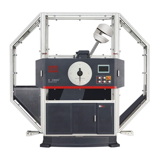
Components of Main Frame Components of Main Frame The following figure shows components of the main frame of E22.452. You can refer to figures of your equipment model, to get familiar with various components of your main frame. For detailed specifications, please refer to Page 20“Technical Specifications”. - Page 18 Components of Main Frame Access control Main shield Left Access control shield Right shield Dial shield Lock Dial pointer Touch screen Sliding door Control panel Impact button Main unit E22 shield Introduction MTS Exceed™ 22 Series Product Information...
- Page 19 Components of Main Frame Hook Speed reducer Filter Motor Power switch Encoder Back door Electric control box Communication port Power interface E22 shield (rear) MTS Exceed™ 22 Series Product Information Introduction...
-
Page 20: Technical Specifications
Technical Specifications Technical Specifications This section provides technical specifications of the main unit of MTS Exceed series of metal pendulum impact testers and illustrates installation sizes of accessories with graphics. Note: Any changes of technical specifications will not be notified to you separately. For any doubts, please contact MTS to confirm critical technical specifications. -
Page 21: General Technical Specifications
General Technical Specifications General Technical Specifications The following technical specifications are universally applicable to MTS series of metal Exceed pendulum impact testers. Parameter E22.452 E22.302 E22.152 Pendulum impact energy (J) Allowable test energy range (J) 45-360 30-240 15-120 Distance from shaft center to specimen center (mm) Impact velocity (m/s) 5.24... - Page 22 General Technical Specifications Environment requirements Indoors only Working temperature 5 to 40 °C Working humidity 5–85%, non-condensing Storage temperature -18 to 49 °C Maximum storage humidity 90% , non-condensing Maximum elevation 2,000 m Gas source 0.4-0.7MPa Power source 200-230 VAC, 5A, 1kW, single phase, 50/60Hz Over-voltage insulation Class 2 Pollution degree...
-
Page 23: Dimensions
Dimensions Dimensions 1522 mm 1255 mm 1698 mm 787 mm E22 main unit MTS Exceed™ 22 Series Product Information Introduction... - Page 24 Dimensions 2145mm 2238mm 787mm E22 shield Introduction MTS Exceed™ 22 Series Product Information...
-
Page 25: Installation
Installation Content Positioning and Ventilation of Main Unit Levelling the Main Frame Installing Shields Controller connection MTS Exceed™ 22 Series Product Information Installation... -
Page 26: Positioning And Ventilation Of Main Unit
Positioning and Ventilation of Main Unit Positioning and Ventilation of Main Unit 22 series pendulum impact tester, and Foundation should be prepared for Exceed at least 1000 mm space should be reserved on the left and right of the foundation, 500 mm space on the back, and 1200 mm space in the front to facilitate operations. -
Page 27: Levelling The Main Frame
Levelling the Main Frame Levelling the Main Frame After installation is ready, you need to level the tester immediately. This can prevent the swinging of its bottom and therefore provides a level test surface to enable more accurate test results. Tools The following tools are required: •... -
Page 28: Installing Shields
Shields are used to prevent specimen from splashing, so as to protect the safety of those entering the danger zones. Each Exceed 22 series tester is equipped with the shields. The shields consist of main shield, left shield, right shield, and several deflector boards. - Page 29 Installing Shields Crosshead Installation of main shield: First fixate the front and back shield parts to the crosshead and then push the front panel of main shield closely against the dial. After that, adjust the main shield to ensure that the center of the two overlaps, and then fix the foot.
- Page 30 Installing Shields Main shield Hinge Lock Right shield Installation of right shield Installation of right shield: Lift the right shield up to let the hinge click, and check whether safety switches are aligned. Make adjustments if necessary. After adjustment, use the lock to fixate the right shield. Installation MTS Exceed™...
- Page 31 Installing Shields Left shield Main shield Lock Hinge Installation of left shield Installation of left shield: Lift the left shield up to let the hinge click, and check whether safety switches are aligned. Make adjustments if necessary. After adjustment, use the lock to fixate the left shield. MTS Exceed™...
- Page 32 Installing Shields Locknut Main shield Electric control box Installation of electric control box: Align screw holes of the electric control box with locknut of the shield and fix them with screws. After the electric control box is level, fasten the screws. Ground wire should be connected between the electric control box and the main unit.
-
Page 33: Controller Connection
Connecting to the Main Power Source Main unit Input power of MTS Exceed 22 series pendulum impact tester adopts three-hole I-type socket (C13 type). Specifications of power cord are H05VV-F, 3G1mm2, which are in compliance with KEMA-KEUR, CEBEC, +S+S+S, VDE, SABS, IEMMEQU, and other certifications. -
Page 34: Connecting Cables
Controller connection Connecting Cables Pay special attention when connecting cables. Make sure the cables are correctly and solidly connected. After connections, check for a second time, to ensure all components are correctly connected. To comply with EMC requirements and realize the optimal performances of the equipment, we recommend you to purchase all system cables from MTS. -
Page 35: Operation
Operation This section describes basic operations and precautions of MTS Exceed 22 series of metal pendulum testers. Content Power Switch (I/O) Dangers of Impact Zone Pendulum Installation Bearing Installation Placing Specimen Control Panel Operations Checks and Preparations Before Use Shortcut Operations Pendulum is the impact device that swings under gravity. - Page 36 Material testing may have potential hazards. Such hazards may cause personal injuries or death. So, only qualified and trained personnel are allowed to operate the equipment. All irrelevance personnel should keep clear when the equipment is in operations. Operation MTS Exceed™ 22 Series Product Information...
-
Page 37: Power Switch (I/O)
Power Switch (I/O) Power Switch (I/O) Power Switch (I/O) Power switch of the main unit is located on the left of the electric control box in the rear of the equipment. Turn the power switch to "I" to supply power to the main unit and controller. -
Page 38: Dangers Of Impact Zone
Dangers of Impact Zone Dangers of Impact Zone When the tester is working, it is important for you not to contact the potential danger zone in any form. You need to understand which is the impact danger zone and know how to use safety gears to protect yourself and others. The following describes the impact zone and preventive measures that should be taken if you work in its peripherals. -
Page 39: Pendulum Installation
Pendulum Installation Pendulum Installation MTS provides a host of pendulums with different energies. You can select the required pendulum based on test requirements and standards. Based on relevant standards and requirements, the energy consumed to break the specimen should be within 10%~80% of the pendulum's maximum energy. -
Page 40: Bearing Installation
Bearing Installation Bearing Installation MTS offers a variety of specimen bearings. Bearing includes anvil, jaw, specimen support plate and screws. Fix the specimen support plate and jaw to the left and right anvils and then place the span alignment block as shown in the following figure. The size between inner sides of the two bearing jaws should correspond to the length of the span alignment block, while the impact blade of the pendulum should match the notch in the middle of the span alignment block. -
Page 41: Placing Specimen
Placing Specimen Placing Specimen During the test, use the specimen clamp to put the Charpy notched specimen onto the jaw bearing. The specimen clamp has the specimen notch alignment function. ★ Note: Both sides of the specimen should press closely against the jaw and bearing, and location of specimen should not change when the clamp is loosened. -
Page 42: Control Panel Operations
Control Panel Operations Control Panel Operations The control panel consists of a touch screen, dial pointer, shield, and 6 buttons to trigger various actions, read data, and set various test parameters. Control Panel The control panel is used to trigger actions, read data, and set parameters. Functions Control Panel Keys Functions... - Page 43 Control Panel Operations Operational Instructions 1. Touch Screen Interfaces 1.1 Main Page After the equipment is powered on, the touch screen displays the main page after about 15s. You can select language on the main page. To ensure test data accuracy, you should perform the clearing action each time the equipment is powered on.
- Page 44 Control Panel Operations After the equipment performs the clearing action, it enters the main page. You can set system language or tap a icon on the right to enter the corresponding operational page. 1.2 Main Unit On the main page, tap Main Unit Control to enter the main unit control page (or Control Page by tapping the left and right arrow icons on other pages).
- Page 45 Control Panel Operations [Impact]: Make the pendulum complete the impact process. Tap the Impact icon, and the the pendulum hanging/release device moves so that the pendulum rotates around the shaft under its weight to impact the specimen. When the impact is complete, the pendulum is rotated counter-clockwise.
- Page 46 Control Panel Operations 1.3 Parameter On the main page, tap Parameter Settings to enter the parameter setting page (or Setting Page by tapping the left and right arrow icons on other pages). As shown In the figure below: You can set impact specimen specifications, pendulum energy, estimated absorption energy, second pendulum fetching pulse, gravity acceleration, time, and other parameters.
- Page 47 Control Panel Operations ★Note: Check whether test parameters are consistent with test conditions before performing the test; otherwise, test results may be inaccurate. 1.4 Empty Swing On the main page, tap Empty Swing Energy Loss to enter the empty swing Energy Loss Page energy loss page (or by tapping the left and right arrow icons on other pages), as shown in the figure below:...
- Page 48 Control Panel Operations 1.5 Pointer Energy On the main page, tap Pointer Energy Loss to enter the pointer energy loss page Loss Page (or by tapping the left and right arrow icons on other pages), as shown in the figure below: Energy loss caused by pointer friction: Turn the pointer to the maximum energy point on the dial and perform impact without putting specimen on the bearing.
- Page 49 Control Panel Operations 1.6 Calculation On the main page, tap Calculation Cycle to enter the calculation cycle page (or Cycle Page by tapping the left and right arrow icons on other pages), as shown in the figure below: Put the pendulum in the vertical position and tap Start Calculation. When the pendulum rotates to about 5°, the clutch throws out and the pendulum is in free swing.
- Page 50 Control Panel Operations 1.7 Print Page On the main page, tap Print Page to enter the print page (or by tapping the left and right arrow icons on other pages), as shown in the figure below: Perform operations based on prompts on the page to complete the print task. Operation MTS Exceed™...
- Page 51 Control Panel Operations Rotate the commissioning state key switch on the control panel to enable the Commissioning commissioning state. State When the key switch is rotated to the horizontal position, the equipment is in commissioning state. Under the commissioning state, protection device can be opened to maintain and commission the equipment.
-
Page 52: Checks And Preparations Before Use
Checks and Preparations Before Use Checks and Preparations Before Use Check 1. Check whether there are other objects within the pendulum's range of swing. 2. Check whether the energy of the used pendulum is up to specimen requirements. 3. Check whether power and signal cables of meters are well connected. Check whether the pendulum blade and bearing are intact, the briquetting block is well pressed, and the span block is well aligned. -
Page 53: Shortcut Operations
Shortcut Operations Shortcut Operations Power-on Press the power switch at the lower right of the tester to power on the system. After about 15 seconds, the touch screen should be on. ★ Note: After the equipment is turned off or in the case of unexpected power outage, wait for 10s to turn on the power again. - Page 54 Shortcut Operations Operation MTS Exceed™ 22 Series Product Information...
-
Page 55: Maintenance
Maintenance Routine Maintenance List Recommended Services Rated 8 hours of operation per day Daily Weekly Yearly Operation-Hours 2000 Clean work area/equipment surfaces. Check energy losses. Check whether the bearing jaw is in the middle Check cables/connections. System checks Check/adjust initial angle. Check whether the brake pad is in excessive Check cable connections System inspection... - Page 56 There are no customer-usable components on MTS Exceed system. Maintenance includes cleaning of main unit and working areas, routine inspections, and main unit regular calibration. Be careful not to spill cleaning agents on the equipment. The equipment may be short-circuited and damaged if you accidentally spill cleaning agents or fluids on electronic components.
-
Page 57: Troubleshooting
Troubleshooting Troubleshooting of Common Faults Fault Description Solution The touch screen is not on or • Check whether power cord is plugged in. displays incorrectly when the • Check whether the voltage is within the predetermined range. equipment is powered on. •... - Page 58 Troubleshooting MTS Exceed™ 22 Series Product Information...
-
Page 59: Equipment Disassembly
Equipment Disassembly Where the system needs to be moved or is at the end of life, the disassembly procedure needs to be initiated. When performing both of the above tasks, you need to dismantle the system. To dismantle the system: 1. - Page 60 Equipment Disassembly MTS Exceed™ 22 Series Product Information...
-
Page 61: Maintenance And Service Logs
Maintenance and Service Logs Content 8 Hours/Day 40 Hours/Month 2000 Hours/Year MTS Exceed™ 22 Series Product Information Maintenance and Service Logs... -
Page 62: Hours/Day
8 Hours/Day 8 Hours/Day 8 Hours/Day Recommended Maintenance Services Shunt calibration Clean working areas check and equipment surfaces Date Performed by Performed by Records Maintenance and Service Logs MTS Exceed™ 22 Series Product Information... -
Page 63: Hours/Month
40 Hours/Month 40 Hours/Month 40 Hours/Month Recommended Maintenance Services Check brake Check cables/ connections Date Performed by Performed by Records MTS Exceed™ 22 Series Product Information Maintenance and Service Logs... -
Page 64: 2000 Hours/Year
2000 Hours/Year 2000 Hours/Year PC Maintenance and System Checks 2000 Hours/Year Recommended Maintenance Services PC Maintenance System checks Back up Test Hard disk Check/clean Check gas Check cable works files defragmentation controller pipe connections (*.Reg/.Cal file) connections Date Performed by Performed by Performed by Performed by... -
Page 65: 2000 Hours
2000 hours 2000 hours System checks 2000 Hours/Year Recommended Maintenance Services System checks Check energy Check clutch/ Check losses brush pendulum proximity switch Date Performed by Performed by Performed by Records MTS Exceed™ 22 Series Product Information Maintenance and Service Logs... -
Page 66: 2000 Hours
2000 hours 2000 hours Main Unit and Working Area 2000 Hours/Year Recommended Maintenance Services Main Unit and Working Area Clean/replace air Clean the main filter unit and working areas Date Performed by Performed by Records Maintenance and Service Logs MTS Exceed™ 22 Series Product Information... - Page 68 MTS Systems Corporation http://www.mts.com/en/Global/index.asp ISO 9001 Certified QMS...
Need help?
Do you have a question about the Exceed 22 Series and is the answer not in the manual?
Questions and answers