JLG 10MSP Operation And Safety Manual
Hide thumbs
Also See for 10MSP:
- Service maintenance manual (196 pages) ,
- Service and maintenance manual (178 pages) ,
- Operation & safety manual (98 pages)

Related Manuals for JLG 10MSP


Summary of Contents for JLG 10MSP
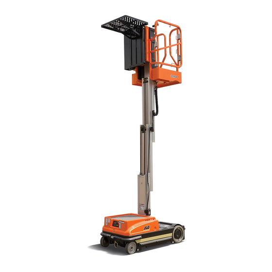
- Page 1 Operation and Safety Manual Original Instructions - Keep this manual with the machine at all times. Model 10MSP PVC 2002 ANSI ® AS/NZS 31215821 September 10, 2019 - Rev A...
- Page 2 @ www.discount-equipment.com Select an option below to find your Equipment We sell worldwide for the brands: Genie, Terex, JLG, MultiQuip, Mikasa, Essick, Whiteman, Mayco, Toro Stone, Diamond Products, Generac Magnum, Airman, Haulotte, Barreto, Power Blanket, Nifty Lift, Atlas Copco, Chicago Pneumatic, Allmand, Miller Curber, Skyjack, Lull,...
- Page 3 WARNING Operating, servicing and maintaining this vehicle or equipment can expose you to chemicals including engine exhaust, carbon monoxide, phthalates, and lead, which are known to the State of California to cause cancer and birth defects or other reproductive harm. To minimize exposure, avoid breathing exhaust, do not idle the engine except as necessary, service your vehicle or equipment in a well-ventilated area and wear gloves or wash your hands frequently when servicing.
- Page 4 The purpose of this manual is to provide owners, users, operators, lessors, and lessees with the precautions and operating procedures essential for the safe and proper machine operation for its intended purpose. Due to continuous product improvements, JLG Industries, Inc. reserves the right to make specification changes without prior notification. Contact JLG Industries, Inc. for updated information.
- Page 5 SAFETY ALERT SYMBOLS AND SAFETY SIGNAL WORDS This is the Safety Alert Symbol. It is used to alert you to the potential personal injury hazards. Obey all safety messages that follow this symbol to avoid possi- ble injury or death INDICATES A POTENTIALIT Y HAZARDOUS SITUATION.
- Page 6 REVISION LOG Original Issue A - September 10, 2019 31215821...
-
Page 7: Table Of Contents
TABLE OF CONTENTS SECTION - PARAGRAPH, SUBJECT PAGE SECTION - PARAGRAPH, SUBJECT PAGE SECTION - 1 - SAFETY PRECAUTIONS Operator Responsibility ..... 2-2 Machine Familiarization . - Page 8 TABLE OF CONTENTS SECTION - PARAGRAPH, SUBJECT PAGE SECTION - PARAGRAPH, SUBJECT PAGE 3.6 BATTERY CHARGING ......3-6 3.9 PLATFORM FUNCTION ENABLE FOOTSWITCH .
- Page 9 TABLE OF CONTENTS SECTION - PARAGRAPH, SUBJECT PAGE SECTION - PARAGRAPH, SUBJECT PAGE Machine Power Up ......3-38 6.3 OPERATOR MAINTENANCE .
- Page 10 TABLE OF CONTENTS SECTION - PARAGRAPH, SUBJECT PAGE SECTION - PARAGRAPH, SUBJECT PAGE LIST OF FIGURES 6-1. Serial Number Plate Location....6-4 6-2.
-
Page 11: Section 1 - Safety Precautions
THE VIBRATION TOTAL VALUE TO WHICH THE HAND-ARM SYSTEM IS SUB- tion, maintenance, application, and operation, please contact JECTED DOES NOT EXCEED 2,5 M/S2. THE HIGHEST ROOT MEAN SQUARE JLG Industries, Inc. (“JLG”). VALUE OF WEIGHTED ACCELERATION TO WHICH THE WHOLE BODY IS SUB- JECTED DOES NOT EXCEED 0,5 M/S2. -
Page 12: Pre-Operation
MEWP. The user shall • This machine can be operated in temperatures of 0° F to determine if personnel are qualified to operate the MEWP 104° F (-20° C to 40° C). Consult JLG for operation outside prior to operation. this range. -
Page 13: Machine Inspection
Ensure that any modifications have been approved ate the machine in hazardous environments unless by JLG. approved for that purpose by JLG. • Avoid any build up of debris on platform floor. Keep mud, • Ensure that the ground conditions are adequate to support... -
Page 14: Operation
• Do not carry materials directly on platform railing unless approved by JLG. • Always ensure that power tools are properly stowed and never left hanging by their cord from the platform work area. -
Page 15: Trip And Fall Hazards
SECTION 1 - SAFETY PRECAUTIONS Trip and Fall Hazards • JLG recommends that the operator utilizes a fall/travel restraint system in the platform with a lanyard attached to an authorized lanyard anchorage point. For further infor- mation regarding fall protection requirements on JLG prod- ucts, contact JLG. -
Page 16: Electrocution Hazards
SECTION 1 - SAFETY PRECAUTIONS Electrocution Hazards Table 1-1. Minimum Approach Distances (M.A.D.) • This machine is not insulated and does not provide protec- Voltage Range MINIMUM APPROACH DISTANCE tion from contact or proximity to electrical current. (Phase to Phase) in Feet (Meters) 0 to 50 KV 10 (3) - Page 17 SECTION 1 - SAFETY PRECAUTIONS • The minimum approach distance may be reduced if insulat- ing barriers are installed to prevent contact, and the barri- ers are rated for the voltage of the line being guarded. These barriers shall not be part of (or attached to) the machine.
-
Page 18: Tipping Hazards
SECTION 1 - SAFETY PRECAUTIONS Tipping Hazards • Ensure that the ground conditions are adequate to support the maximum tire load indicated on the tire load decals located on the chassis adjacent to each wheel. Do not travel on unsupported surfaces. •... -
Page 19: Crushing And Collision Hazards
SECTION 1 - SAFETY PRECAUTIONS • Do not increase the platform size with unauthorized deck Crushing And Collision Hazards extensions or attachments, increasing the area exposed to • Approved head gear must be worn by all operating and wind will decrease stability. ground personnel. -
Page 20: Lifting And Hauling
SECTION 1 - SAFETY PRECAUTIONS LIFTING AND HAULING • Always post a lookout when driving in areas where vision is obstructed. General • Keep non-operating personnel at least 6 ft (1.8 m) away • Never allow personnel in platform while lifting or hauling. from machine during all operations. -
Page 21: Maintenance
SECTION 1 - SAFETY PRECAUTIONS MAINTENANCE • Always relieve hydraulic pressure from all hydraulic cir- cuits before loosening or removing hydraulic compo- This sub-section contains general safety precautions which nents. must be observed during maintenance of this machine. • DO NOT attempt to repair or tighten any hydraulic hoses Additional precautions to be observed during machine or fittings while the machine is powered on or when the maintenance are inserted at the appropriate points in this... -
Page 22: Battery Hazards
SECTION 1 - SAFETY PRECAUTIONS Battery Hazards • Use only replacement parts or components that are approved by JLG. To be considered approved, replace- • Always disconnect batteries when servicing electrical ment parts or components must be identical or equiva- components or when performing welding on the lent to original parts or components. -
Page 23: Section 2 - Preparation And Inspection
SECTION 2 - PREPARATION AND INSPECTION SECTION 2. PREPARATION AND INSPECTION PERSONNEL TRAINING Enough knowledge of the mechanical operation of the machine to recognize a malfunction or potential malfunction. The Mobile Elevating Work Platform (MEWP) is a personnel han- dling device; so it is necessary that it be operated and main- The safest means to operate the machine where over- tained only by trained personnel. -
Page 24: Training Supervision
Table 2-1 explains the machine inspections and maintenance mine if personnel are qualified to operate the MEWP prior to recommended by JLG Industries, Inc. Consult local regulations operation. The user shall ensure that after familiarization, the for further requirements for MEWPs. Frequency of inspections... -
Page 25: Inspection And Maintenance Table
Inspection forms are available from JLG. Use the Service and Maintenance Manual to perform inspections. JLG INDUSTRIES, INC. RECOGNIZES A FACTORY TRAINED SERVICE TECHNICIAN AS A PERSON WHO HAS SUCCESSFULLY COM- PLETED THE JLG SERVICE TRAINING SCHOOL FOR THE SPECIFIC JLG PRODUCT MODEL. -
Page 26: Pre-Start Inspection
SECTION 2 - PREPARATION AND INSPECTION PRE-START INSPECTION Platform Gate – Keep gate and surrounding area clean and unobstructed. Verify the gate closes prop- erly and is not bent or damaged. Keep gate closed at The Pre-Start Inspection should include each of the following: all times except when entering/exiting the platform Cleanliness –... -
Page 27: Walk-Around Inspection
SECTION 2 - PREPARATION AND INSPECTION WALK-AROUND INSPECTION Begin the Walk-Around Inspection at item one as noted on Fig- TO AVOID POSSIBLE INJURY, BE SURE MACHINE POWER IS “OFF” DURING ure 2-1. Continue around machine checking each item in WALK-AROUND INSPECTION. sequence for the conditions listed in the following check list. -
Page 28: Walk-Around Inspection
SECTION 2 - PREPARATION AND INSPECTION Figure 2-1. Walk-Around Inspection 31215821... -
Page 29: Walk-Around Inspection Components
SECTION 2 - PREPARATION AND INSPECTION Walk-Around Inspection Components Motor/Pump/Reservoir Unit - No evidence of hydraulic leaks. Refer to Figure 2-1. Manual Descent Control Valve - Refer to Inspection INSPECTION NOTE: On all components, make sure there are Note. no loose or missing parts, they are securely fastened, and no Platform Control Console - Platform control;... -
Page 30: Function Check
SECTION 2 - PREPARATION AND INSPECTION FUNCTION CHECK b. Ensure all machine functions are disabled when Emergency Stop Button is activated (pressed in). Once the Walk-Around Inspection is complete, perform a func- c. Operate all functions. Check all limit, cut-out, and tion check of all systems in an area free of overhead and ground enable switches are functioning properly: level obstructions. - Page 31 SECTION 2 - PREPARATION AND INSPECTION • Platform Joystick Enable, Footswitch NOTE: (Australian Spec machines also include a platform gate lock/release lever mechanism on top of each gate that Enable, and Left Hand Lift Enable - The must be pressed down to open the platform gate. Check machine will not operate (drive or lift) unless that the lock/release on each gate latches properly when all these switches are pressed and held during...
- Page 32 SECTION 2 - PREPARATION AND INSPECTION Ensure the Object Detection System (if equipped) functions properly (refer to Section 3): • Raise the platform to a height of 24 in (61 cm) or more. • Have someone on the ground place an object of 15 lb (7 kg) or greater on the object detec- tion pad.
- Page 33 @ www.discount-equipment.com Select an option below to find your Equipment We sell worldwide for the brands: Genie, Terex, JLG, MultiQuip, Mikasa, Essick, Whiteman, Mayco, Toro Stone, Diamond Products, Generac Magnum, Airman, Haulotte, Barreto, Power Blanket, Nifty Lift, Atlas Copco, Chicago Pneumatic, Allmand, Miller Curber, Skyjack, Lull,...
-
Page 34: Section 3. Machine Operation
SECTION 3 - MACHINE OPERATION SECTION 3. MACHINE OPERATION GENERAL MACHINE DESCRIPTION This machine is a Mobile Elevating Work Platform (MEWP) with attached adjustable material handling tray, mounted to an ele- THE MANUFACTURER HAS NO DIRECT CONTROL OVER MACHINE APPLICA- vating mast mechanism. -
Page 35: Operating Characteristics And Limitations
SECTION 3 - MACHINE OPERATION OPERATING CHARACTERISTICS AND LIMITATIONS Stability This machine, as originally manufactured by JLG and operated Placards within its rated capacity on a smooth firm surface within the Important points to remember during operation are provided at... -
Page 36: Machine Operation
SECTION 3 - MACHINE OPERATION MACHINE OPERATION Getting Started The following conditions must be met before the machine can be operated from either the Ground or Platform Controls: • Batteries contain enough voltage to operate. Low Battery warning not indicated on Ground Control Station. •... -
Page 37: Machine Operating Component Locations
SECTION 3 - MACHINE OPERATION 1. Ground Control Station (Module) 2. Internal Platform Manual Descent Valve (Under Hood) 3. Battery Charger AC Recepta- cle and Charging Status LED Indicators 4. Platform Enable Footswitch 5. Platform Entry Gate 6. Platform 7. Platform Control Console 8. -
Page 38: Hood (Carry Deck)
SECTION 3 - MACHINE OPERATION HOOD (CARRY DECK) Removal To remove the hood, loosen the attach screw on the front of the hood. Lift the hood at the front to clear the rubber sealing gasket on the base frame and slide the hood forward while lifting up to completely remove it from the machine. -
Page 39: Battery Charging
SECTION 3 - MACHINE OPERATION BATTERY CHARGING Battery Low Voltage Warning Indicators The Platform Control Console and Ground Control Station indicate battery low voltage at three Warning Levels. Table 3-1. Battery Low Voltage Warning Indicators INDICATOR LOCATION WARNING ACTION REQUIRED RESULT LEVEL TO CLEAR FAULT... -
Page 40: To Charge Batteries
SECTION 3 - MACHINE OPERATION To Charge Batteries Always grounded AC outlet. This machine is equipped with an AC voltage input/DC voltage Connect charger to an output battery charger. The charger automatically terminates outlet that has been charging when the batteries reach full capacity. properly installed and NOTE: The platform drive function is disabled when the battery grounded in accor-... -
Page 41: Battery Charging Status Indicators
SECTION 3 - MACHINE OPERATION Battery Charging Status Indicators The battery charging status indicators are located just above the Charger AC input receptacle on the center cover section at the rear of the machine. When first plugged in, the charger will automatically turn on and go through a short LED indicator self-test (all LEDs will flash in an up-down sequence for two seconds), then charging will begin. - Page 42 SECTION 3 - MACHINE OPERATION voltage is low (below 104VAC), then the charging If a fault occurred anytime during charging, a fault power will be reduced to avoid high input currents. If indication is given by flashing the RED ‘FAULT’ LED the ambient temperature is too high, then the with a code corresponding to the error.
- Page 43 SECTION 3 - MACHINE OPERATION [1 FLASH] Battery Voltage High: auto-recover. Indi- [5 FLASH] Over-Temperature: auto-recover. Indicates cates a high battery pack voltage. charger has shutdown due to high internal tempera- ture which typically indicates there is not sufficient air- [2 FLASH] Battery Voltage Low: auto-recover.
-
Page 44: Ground Control Station
SECTION 3 - MACHINE OPERATION GROUND CONTROL STATION 1. Platform/Off/Ground Selector Switch 2. Emergency Stop/Shut Down Button 3. Brake Release Button 4. Platform Up Button 5. Platform Down Button 6. Machine Status LCD Display NOTE: The Ground Control Station Mod- ule is fully programmable. -
Page 45: Platform/Off/Ground Selector Switch
SECTION 3 - MACHINE OPERATION Platform/Off/Ground Selector Switch NOTE: SLEEP MODE - During operation if no control functions have been activated for 5 minutes (default programmable setting), the ground control module will power down the POWER OFF machine to conserve battery power. Cycle power back on using either the main power selector switch (key) or the Turn to this position to power machine off emergency stop/power down button either on the plat-... -
Page 46: Brake Release Button
SECTION 3 - MACHINE OPERATION Brake Release Button Platform Up and Down Buttons The machine must be POWERED ON and the Ground Control Station set to the GROUND CONTROL MODE to manually release PUSH IN - the brakes. The brakes only DISENGAGE (electrically) when the TO ELEVATE Platform joystick control is moved off center during driving or are manu- RELEASE -... -
Page 47: Machine Status Lcd Display
SECTION 3 - MACHINE OPERATION Machine Status LCD Display 00000.0 At power-up and during operation, the LCD display on the Ground Control Module displays the current machine operating status. The following illustration explains the symbol indica- tions. Figure 3-6. LCD Display Symbols 1. -
Page 48: Tilt Alarm Warning
SECTION 3 - MACHINE OPERATION Tilt Alarm Warning In the LCD Display Symbols (refer to Figure 3-6., item 2), the Function Display or Function Disabled Indicators will vary as shown following: The Ground Control Station LCD screen flashes a fault code and gives an audible warning. -
Page 49: Lcd Display - Operating Fault Conditions
SECTION 3 - MACHINE OPERATION Table 3-2. LCD Display - Operating Fault Conditions PLATFORM FAULT FAULT DESCRIPTION/ LCD SYMBOL SCREEN LCD TEXT SCREEN TO CORRECT PROBLEM LEDs CODE MACHINE CONDITION FLASHING To Engage Brakes - Press Brake Brakes Released - —... - Page 50 SECTION 3 - MACHINE OPERATION Table 3-2. LCD Display - Operating Fault Conditions (Continued) PLATFORM FAULT FAULT DESCRIPTION/ LCD SYMBOL SCREEN LCD TEXT SCREEN TO CORRECT PROBLEM LEDs CODE MACHINE CONDITION FLASHING Drive Motor Brush Wear Warning Drive Motor Brushes Require Service (Counts down 25 hrs.
- Page 51 The fault conditions shown in this table are fault conditions that the operator may be able to resolve. Should a fault occur that cannot be corrected at the operator’s level, the problem must be referred to a mechanic qualified to repair this model of JLG Lift. A complete table of fault codes is listed in the Troubleshooting section of the Service and Maintenance Manual.
-
Page 52: Platform Control Console
SECTION 3 - MACHINE OPERATION PLATFORM CONTROL CONSOLE 1. On/Off Key Switch 2. Emergency Stop/Shut Down Switch 3. Function Enable Lever 4. Single Function Joystick Control 5. Drive Speed Setting Selector Switch 6. Horn Button 7. Platform Control Display Panel 8. -
Page 53: General
SECTION 3 - MACHINE OPERATION General Platform On/Off Key Switch NOTE: SLEEP MODE - During operation if no control functions have been activated for 10 minutes (default programma- At the Platform Control Console ble setting), the ground control module will power the - Set the On/Off Key Switch to machine down to conserve battery power. -
Page 54: Platform Emergency Stop/Shut Down Button
SECTION 3 - MACHINE OPERATION Platform Emergency Stop/Shut Down Button Horn Button NOTE: The Platform and Ground Control Station Emergency When the machine is Stop/Shut Down Buttons must both be in the RESET posi- powered on, pressing tion to operate machine. this button will sound the Horn. -
Page 55: Joystick Function Enable Lever
SECTION 3 - MACHINE OPERATION Joystick Function Enable Lever Single Function Joystick Control The single function joystick control on the platform control con- Joystick Function sole operates drive/steer functions of the machine. The Left Enable Lever Hand Lift control operates the lift up and down functions of the machine. -
Page 56: Drive Speed Setting Selector Switch
SECTION 3 - MACHINE OPERATION Drive Speed Setting Selector Switch Drive Speed Setting Selector Switch NOTE: When the platform is elevated, the maximum drive speed 1. Selector Switch (on top is automatically cut back to approximately 10%. The of platform control con- Ground Control Module LCD screen will display a turtle sole joystick) when in this mode, Refer to Machine Status LCD Display in... -
Page 57: Platform Control Display Panel
SECTION 3 - MACHINE OPERATION Platform Control Display Panel Battery Charge/Flash (Fault) Code Indicator LEDS On normal power-up and operation this series of ten (10) LEDs visually indicates the amount of charge remaining in the batteries. The number of LEDs lit will change depending on the level of charge in the batteries. - Page 58 SECTION 3 - MACHINE OPERATION Drive Speed Setting Indicator The five GREEN LEDs on the top of this indicator display the drive speed setting with the TURTLE representing the MINIMUM speed setting and the RABBIT representing the MAXIMUM speed setting. 31215821 3-25...
- Page 59 SECTION 3 - MACHINE OPERATION Drive Mode Lift Mode 1. Activate the Lift Mode 1. Activate the Drive Mode using the Drive/Lift Mode using the Drive/Lift Mode Selector switch. Selector switch. 2. Platform LIFT DOWN Direc- tion Within 5 seconds of 3.
-
Page 60: Left Hand Lift
SECTION 3 - MACHINE OPERATION Left Hand Lift The Left Hand Lift is attached to the top left rail of the platform. The enable lever functions in conjunction with the footswitch and platform control console function enable lever. All three must be pressed and held while operating any functions. -
Page 61: Platform Function Enable Footswitch
SECTION 3 - MACHINE OPERATION PLATFORM FUNCTION ENABLE FOOTSWITCH Platform Function Enable Footswitch 1. Footswitch DO NOT REST FOOT ON THE ENABLE FOOT SWITCH DURING MACHINE POWER UP, OPERATING ANY CONTROLS DURING MACHINE POWER UP OTHER THAN Press down and hold THE POWER ON/OFF KEY SWITCH OR RESETTING THE E-STOP/SHUT DOWN while operating any SWITCHES WILL CAUSE THE MACHINE TO DISPLAY AN ERROR. -
Page 62: 3.10 Platform Manual Descent Control Valve
SECTION 3 - MACHINE OPERATION 3.10 PLATFORM MANUAL DESCENT CONTROL VALVE Activating the Internal Manual Descent Valve To activate the internal manual descent valve, remove the hood (carry deck) from the machine. Locate the valve (just below the battery charger), then operate per the following instructions; CRUSHING HAZARD - BE AWARE OF DESCENDING PLATFORM WHEN MANU- ALLY LOWERING THE PLATFORM. -
Page 63: Activating The Remote Manual Descent
SECTION 3 - MACHINE OPERATION Activating the Remote Manual Descent (If Equipped) To activate the remote manual descent, follow the below instructions: Pull out the lever on the outer side of the machine TO LOWER the platform. Release the lever TO STOP platform descent when... -
Page 64: 3.11 Platform Configuration
2. Platform Load (Operator) 6. Ext. Cord Wrap Hooks THE PLATFORM. FOR FURTHER INFORMATION REGARDING FALL PROTEC- 7. Lanyard Attach Point 3. Platform Swing-In Entry Gate TION REQUIREMENTS ON JLG PRODUCTS, CONTACT JLG. 8. Hood (Carry Deck) 4. Material Handling Tray 31215821 3-31... -
Page 65: Object Detection System (If Equipped)
SECTION 3 - MACHINE OPERATION Object Detection System (If Equipped) If an object is detected, have the object cleared by someone on the ground, reset the system by pressing the horn button once, The Object Detection System is designed to detect an object then continue to lower the machine normally. -
Page 66: Manual Tray Height Adjustment
SECTION 3 - MACHINE OPERATION Manual Tray Height Adjustment The manual tray is designed to carry up to 254 lb (115 kg) of weight. It can be quickly raised or lowered vertically on the front of the mast assembly using the tray handle release. REMOVE ALL WEIGHT FROM THE TRAY BEFORE ENGAGING THE TRAY RELEASE BAR TO LOWER OR RAISE THE TRAY. -
Page 67: Power Tray Height Adjustment
SECTION 3 - MACHINE OPERATION Power Tray Height Adjustment The power tray is designed to carry up to 198 lb (90 kg) of weight. It can be quickly and easily raised or lowered vertically on the front of the mast assembly using the switch located in the platform. -
Page 68: Cargo Strap (Option)
SECTION 3 - MACHINE OPERATION 3.12 PARKING MACHINE Cargo Strap (Option) The retractable cargo strap is designed to help secure objects Drive machine to a well-protected and well-ventilated loaded onto the material handling tray while machine is in oper- area. ation. -
Page 69: Transporting, Lifting And Tie-Down Proce
SECTION 3 - MACHINE OPERATION 3.13 TRANSPORTING, LIFTING AND TIE-DOWN PROCEDURES General This machine may be transported to a work site using the fol- lowing methods: • Driven around on its base wheels if travel surface area per- mits. • Moved with a forklift truck using the forklift pockets in the base frame. -
Page 70: Vehicle Transport Using The Tie-Down Loops
SECTION 3 - MACHINE OPERATION Vehicle Transport Using the Tie-Down Loops With the machine on the transport vehicle in position to be tied down and machine powered down (brakes engaged), use the following guidelines for restraining the machine during trans- port. -
Page 71: Programmable Security Lock (Psl ) (Option)
SECTION 3 - MACHINE OPERATION 3.14 PROGRAMMABLE SECURITY LOCK (PSL ) (OPTION) ™ The optional keyless Programmable Security Lock switch can be programmed with a four-digit Operator’s Code to allow only those persons with the code to power-up and operate the machine. -
Page 72: Machine Power Down
SECTION 3 - MACHINE OPERATION Machine Power Down Changing the Operator’s Code The Operator’s Code can be changed should the need occur. A At the Ground Control Station set the main power separate Permanent Code matched to the serial number of the selector switch to the OFF position. -
Page 73: 3.15 Decal Installation
SECTION 3 - MACHINE OPERATION 3.15 DECAL INSTALLATION OAR00170 Figure 3-19. Manual Tray - Decal Installation 3-40 31215821... -
Page 74: Manual Tray - Decal Installation
SECTION 3 - MACHINE OPERATION OAR00180 Figure 3-20. Manual Tray - Decal Installation 31215821 3-41... -
Page 75: Manual Tray - Decal Installation
SECTION 3 - MACHINE OPERATION Table 3-4. Manual Tray - Decal Installation ANSI ANSI ANSI ANSI ANSI Item (ENG) (FRE) (ENG) (SPA) (POR) (CHI) (JPN) (ENG) 1701640 1701640 1701640 1701640 1701640 1701640 1701640 1701640 1001213582 1001213582 1001213582 1001213582 1001213582 1001213582 1001213582 1001213582 1705992... - Page 76 SECTION 3 - MACHINE OPERATION Table 3-4. Manual Tray - Decal Installation ANSI ANSI ANSI ANSI ANSI Item (ENG) (FRE) (ENG) (SPA) (POR) (CHI) (JPN) (ENG) 1703786 1706094 1705937 1706096 1706078 1706084 1706088 1706092 1706078 1706078 1705938 1706095 1706083 1706087 1706091 1705995 1706094...
-
Page 77: Power Tray - Decal Installation
SECTION 3 - MACHINE OPERATION 18 6 OAR00190 Figure 3-21. Power Tray - Decal Installation 3-44 31215821... - Page 78 SECTION 3 - MACHINE OPERATION OAR00200 Figure 3-22. Power Tray - Decal Installation 31215821 3-45...
-
Page 79: Power Tray - Decal Installation
SECTION 3 - MACHINE OPERATION Table 3-5. Power Tray - Decal Installation ANSI ANSI ANSI ANSI ANSI Item (ENG) (FRE) (ENG) (SPA) (POR) (CHI) (JPN) (ENG) 1701640 1701640 1701640 1701640 1701640 1701640 1701640 1701640 1001213582 1001213582 1001213582 1001213582 1001213582 1001213582 1001213582 1001213582 1705992... -
Page 80: Power Tray - Decal Installation
SECTION 3 - MACHINE OPERATION Table 3-5. Power Tray - Decal Installation ANSI ANSI ANSI ANSI ANSI Item (ENG) (FRE) (ENG) (SPA) (POR) (CHI) (JPN) (ENG) 1703786 1706094 1705937 1706096 1706084 1706088 1706092 1706078 1706078 1705938 1706095 1706078 1706083 1706087 1706091 1705995 1001093992... - Page 81 SECTION 3 - MACHINE OPERATION 3-48 31215821...
-
Page 82: Section 4 - Emergency Procedures
SECTION 4 - EMERGENCY PROCEDURES SECTION 4. EMERGENCY PROCEDURES GENERAL INFORMATION Platform Caught Overhead If the platform becomes jammed or snagged in overhead This section explains the steps to be taken in case of an emer- structures or equipment, do the following: gency situation during operation. -
Page 83: Incident Notification
JLG Industries, Inc. must be notified immediately of any inci- FOLLOWING ANY INCIDENT, THOROUGHLY INSPECT THE MACHINE. DO NOT ELE- dent involving a JLG product. Even if no injury or property VATE THE PLATFORM UNTIL IT IS CERTAIN THAT ALL DAMAGE HAS BEEN damage is evident, JLG must be contacted by telephone and REPAIRED AND THAT ALL CONTROLS ARE OPERATING CORRECTLY. -
Page 84: Section 5. Accessories
SECTION 5 - ACCESSORIES SECTION 5. ACCESSORIES Table 5-1. Available Accessories Market Accessory ANSI ANSI Japan (USA Only) Scanner Pocket 31215821... -
Page 85: Scanner Pocket
SECTION 5 - ACCESSORIES SCANNER POCKET This accessory offers a secure location in the platform to store handheld scanners. 31215821... -
Page 86: Section 6. General Specifications And Operator Maintenance
SECTION 6 - GENERAL SPECIFICATIONS AND OPERATOR MAINTENANCE SECTION 6. GENERAL SPECIFICATIONS AND OPERATOR MAINTENANCE 6.1 INTRODUCTION Other Publications Available Specific to This Machine Service and Maintenance Manual This section of the manual provides additional necessary information to the operator for proper operation and mainte- GLOBAL . -
Page 87: 6.2 General Specifications
SECTION 6 - GENERAL SPECIFICATIONS AND OPERATOR MAINTENANCE 6.2 GENERAL SPECIFICATIONS SPECIFICATION 10MSP Machine Specifications * Maximum Drive Speeds: (Operator Variable) 5 mph (8 kp/h) Maximum Operating Wind Speed: SPECIFICATION 10MSP (For indoor use only) ANSI/CSA: 0 mph (0 m/s) -
Page 88: Electrical Specifications
SECTION 6 - GENERAL SPECIFICATIONS AND OPERATOR MAINTENANCE Electrical Specifications Platform Data SPECIFICATION 10MSP SPECIFICATION 10MSP System Voltage: 24 Volts DC Occupants: (Persons allowed in Platform) Battery Specifications: Maximum Work Load (Capacity): Battery Type: AGM (VRLA) (Sealed) Platform: 352 lb (160 kg) 4 - 6 V DC;... -
Page 89: Serial Number Location
SECTION 6 - GENERAL SPECIFICATIONS AND OPERATOR MAINTENANCE Serial Number Location The serial number plate is located on the right side of the machine behind the caster wheel. Figure 6-1. Serial Number Plate Location 31215821... -
Page 90: 6.3 Operator Maintenance
NOTE: Aside from JLG recommendations, it is not advisable to mix oils of different brands or types, as they may not con- tain the same required additives or be of comparable vis- cosities. -
Page 91: Standard Utto Specs
SECTION 6 - GENERAL SPECIFICATIONS AND OPERATOR MAINTENANCE Table 6-1. Standard UTTO Specs Table 6-2. UCon Hydrolube HP-5046 Specs SAE Grade 10W30 Gravity, API 29.0 Specific Gravity, 20/20°F 1.082 Pour Point, °C(°F) <-50(<58) Density, Lb/Gal. 60°F 7.35 Appearance Red Liquid Pour Point, Max -46°F (-43°C) Viscosity... -
Page 92: Lubrication Specifications
SECTION 6 - GENERAL SPECIFICATIONS AND OPERATOR MAINTENANCE Table 6-3. Lubrication Specifications SPECIFICATIONS MPG - Multipurpose Grease having a minimum dripping point of 350° F. Excellent water resistance and adhesive qualities, and being of extreme pressure type. (Timken OK 40 pounds mini- mum.) EPGL - Extreme Pressure Gear Lube (oil) meeting API service classifi- cation GL-5 or MIL-Spec MIL-L-2105. -
Page 93: Lubrication Points
SECTION 6 - GENERAL SPECIFICATIONS AND OPERATOR MAINTENANCE Figure 6-2. Lubrication Points 31215821... -
Page 94: Lubrication Intervals For Various Components
SECTION 6 - GENERAL SPECIFICATIONS AND OPERATOR MAINTENANCE Table 6-4. Lubrication Intervals for Various Components (See Note) INTERVAL NO/TYPE ITEM COMPONENT LUBE/METHOD COMMENTS LUBE POINTS MONTHS MONTHS YEAR YEARS Check fluid level every day. Change hydraulic oil every 2 years. NOTE: Prior to checking hydraulic oil level, operate Fill To Full Line on... -
Page 95: 6.4 Battery Maintenance
JLG recommends that any replacement tire be the same size and brand as originally installed on the machine or offered by JLG as an approved replacement. Please refer to the JLG Parts Manual for the part number of the approved tires for a partic- ular machine model. -
Page 96: Wheel Installation
Wheel Installation If any of the following is discovered during tire inspection, measures must be taken to remove the JLG product from ser- vice immediately. Arrangements must be made for replace- It is extremely important to apply and maintain proper wheel ment of the tire(s) or tire assembly(s). -
Page 97: Wheel Bolt Tightening Sequence
SECTION 6 - GENERAL SPECIFICATIONS AND OPERATOR MAINTENANCE Tighten the wheel bolts to the proper torque to prevent The tightening of the wheel bolts should be done in wheels from coming loose. Use a torque wrench to tighten stages. Following the recommended sequence, the fasteners. -
Page 98: 6.6 Ground Control Station - Programming
SECTION 6 - GENERAL SPECIFICATIONS AND OPERATOR MAINTENANCE 6.6 GROUND CONTROL STATION - PROGRAMMING Programming Levels There is one password protected programming level available General to the Operator: The Ground Control Station on this machine allows on-board • Level 3: Operator’s Settings - Level 3 Password: 33271 programming of various component and control function per- sonality settings. -
Page 99: Programming Items
SECTION 6 - GENERAL SPECIFICATIONS AND OPERATOR MAINTENANCE Programming Items • Set Polarity of Keypad Code - Turns ON or OFF the Pro- grammable Security Lock switch circuit, if equipped. Allows programming of the items shown in Table 6-4. The fol- •... -
Page 100: Programmable Settings And Factory Presets
SECTION 6 - GENERAL SPECIFICATIONS AND OPERATOR MAINTENANCE Table 6-6. Programmable Settings and Factory Presets LEVEL PROGRAMMABLE ITEM FACTORY PRESET SETTING RANGE Back to Main — Return to Main Menu Set Language 1. English 6. Italian 2. German 7. Swedish 3. -
Page 101: Activating Programming Mode
SECTION 6 - GENERAL SPECIFICATIONS AND OPERATOR MAINTENANCE Activating Programming Mode NOTE: If machine does not power up, check that both the Ground Control Station - Emergency Stop Button, and the Plat- form Control Console - Emergency Stop Button, are in the RESET position. -
Page 102: Entering Password
SECTION 6 - GENERAL SPECIFICATIONS AND OPERATOR MAINTENANCE Entering Password Programming Mode Selection Entering Password (33271) Programming Mode Selection 1. The Brake Release button (1) moves the box (around digit) from left to right to 1. Use Platform UP/DOWN buttons (1) to move the selection box (2) up or down select which digit to change. -
Page 103: Selecting Programmable Item To Adjust
SECTION 6 - GENERAL SPECIFICATIONS AND OPERATOR MAINTENANCE Selecting Programmable Item to Adjust Adjusting Programmable Setting Adjusting Programmable Setting 1. Adjust the programmable setting using the Platform UP/DOWN buttons (1), Selecting Programmable Item to Adjust see Table 6-6. for range of settings for that item. 1. -
Page 104: 6.7 Drive Motor Brush Wear - Warning Indication
SECTION 6 - GENERAL SPECIFICATIONS AND OPERATOR MAINTENANCE 6.7 DRIVE MOTOR BRUSH WEAR - WARNING INDICATION NOTE: Only the drive function when used will affect the hour meter count down once the warning has been activated. The machines drive motors include brush wear sensors that The machine will operate normally until the last 10 sec- activate a warning indicating the drive motor brushes will onds of the 25 hour countdown. - Page 105 SECTION 6 - GENERAL SPECIFICATIONS AND OPERATOR MAINTENANCE 6-20 31215821...
-
Page 106: Section 7. Inspection And Repair Log
SECTION 7 - INSPECTION AND REPAIR LOG SECTION 7. INSPECTION AND REPAIR LOG Machine Serial Number _____________________________________ Table 7-1. Inspection and Repair Log DATE COMMENTS 31215821... - Page 107 @ www.discount-equipment.com Select an option below to find your Equipment We sell worldwide for the brands: Genie, Terex, JLG, MultiQuip, Mikasa, Essick, Whiteman, Mayco, Toro Stone, Diamond Products, Generac Magnum, Airman, Haulotte, Barreto, Power Blanket, Nifty Lift, Atlas Copco, Chicago Pneumatic, Allmand, Miller Curber, Skyjack, Lull,...
Need help?
Do you have a question about the 10MSP and is the answer not in the manual?
Questions and answers