Table of Contents
Advertisement
Available languages
Available languages
iLumin Plus
Installation Quick Guide
iLumin Plus
Risk of Fire, Electrical Shock, Cuts or other Casualty Hazards- Installation and maintenance of this
product must be performed by a qualified electrician. This product must be installed in accordance
with the applicable installation code by a person familiar with the construction and operation of
the product and hazards involved. For continued protection against shock hazard replace all covers
and guards after field wiring is completed.
Before installing or performing any service, the power MUST be turned OFF at the branch circuit breaker.
According to NEC 240-83(d), if the branch is used as the main switch for a fluorescent lighting circuit,
the circuit breaker should be marked with "SWD" . All installations should be in compliance with the
National Electric Code and all state and local codes.
Risk of Fire and Electric Shock- Make certain power is OFF before starting installation or attempting
any maintenance. Disconnect power at fuse or circuit breaker. iLumin Plus models may contain
circuits from more than one power source.
Risk of Burn- Disconnect power and allow fixture to cool before handling or servicing.
Risk of Personal Injury- Due to sharp edges, handle with care. Always use at least two people when
lifting and mounting heavy or large units
Failure to comply with these instructions may result in serious injury (including death) and property
damage.
DISCLAIMER OF LIABILITY: Eaton assumes no liability for damages or losses of any kind that may arise from the
improper, careless, or negligent installation, handling or use of this product.
IMPORTANT: Read carefully before installing fixture. Retain for future reference.
NOTICE: Fixture may become damaged and/or unstable if not installed properly.
Note: Specifications and dimensions subject to change without notice.
ATTENTION Receiving Department: Note actual fixture description of any shortage or noticeable damage on
delivery receipt. File claim for common carrier (LTL) directly with carrier. Claims for concealed damage must be
filed within 15 days of delivery. All damaged material, complete with original packing must be retained.
NOTICE: If a room is wired for two circuits using two separate hot leads, it is very important to connect only one
circuit per relay. Both circuits must be fed from the same phase.
NOTICE: Ensure that all modules are firmly seated on the DIN rails before beginning field wiring.
NOTICE: The high voltage supply should be fed to the cabinet via an external isolation breaker with sufficient
capacity for the planned installation.
NOTICE: Ensure that the supply is fully isolated at an external breaker before opening doors. Test that power has
been removed before starting to handle conductors.
NOTICE: Ensure that high voltage and low voltage wiring remains separate.
NOTICE: All new wiring must be fully verified before applying power.
NOTICE: Designed for indoor installation and use only. Dry location rated.
Applies to Model #s:
ILS-0010
ILS-1100
ILS-0020
ILS-2000
WARNING
ILM-2201
ILM-0041
ILL-3300
ILM-2200
ILM-3000
ILL-3301
ILM-2111
ILM-3001
ILL-4400
ILM-2110
ILM-4000
ILL-4401
INS #
ILM-0040
ILM-4001
Advertisement
Table of Contents

Related Manuals for Eaton iLumin Plus


Summary of Contents for Eaton iLumin Plus
- Page 1 Failure to comply with these instructions may result in serious injury (including death) and property damage. DISCLAIMER OF LIABILITY: Eaton assumes no liability for damages or losses of any kind that may arise from the improper, careless, or negligent installation, handling or use of this product.
-
Page 2: Installation Steps
Connect panel power Connect relay wiring Connect 0-10V dimmer wiring Connect 2 wire data bus wiring Connect iLumin Plus network wiring Clear all power circuit wiring for errors Energize panel power circuit Energize relay and lighting power circuits 10. Coordinate system startup... -
Page 3: Please Read This First
• Allow adequate space for future maintenance of the unit. • The iLumin Plus cabinet must be installed only by a Do not install in a location that will later be difficult to... -
Page 4: General Information
• EG2: Ethernet gateway access • CR1-RJ: PC network connection • The iLumin Plus panel is designed to be mounted vertically • Use suitable conduits and couplers to link the raceways to Note: Ensure at least three(3) inches of air space around the the controller chassis iLumin Plus enclosure. - Page 5 16.00 Note: Ensure at least three(3) inches of air space around the 8.00 Ă .91 iLumin Plus enclosure. 3 INCH SPACE AROUND ENCLOSURE PANEL 16.00 3 INCH SPACE AROUND ENCLOSURE PANEL Ă .91 8.00...
-
Page 6: Connecting The Supply
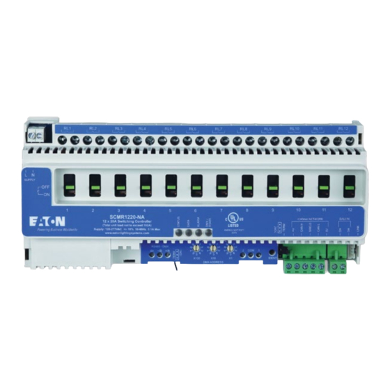
Remove all wire cuttings from the enclosure. Relays are numbered 1-12 on each SCMR1220-NA module. 0-10V Dimmer Wiring Detail Using the iLumin Plus programming software each relay can be programmed to meet control requirements. The table Twelve: 0-10V Dimmers below indicates the minimum wires size to be used with various load currents. - Page 7 PC will have access to all iLumin Plus devices on the lighting network. In a medium or large iLumin Plus panel one side of the CR1- RJ will not have wires connected. This terminal is used to connect to other iLumin Plus panels.
- Page 8 Connecting to the building LAN or VLAN Sample iLumin Plus network systems Medium and large iLumin Plus panels may include the EG2 Below are some examples of a simple iLumin Plus network optional ethernet connection device. The EG2 acts as a host and a complex iLumin Plus network application.
- Page 9 Risque d’incendie et de décharge électrique – Assurez-vous que l’alimentation électrique est HORS TENSION avant de commencer l’installation ou de tenter d’en faire l’entretien. Coupez l’alimentation électrique au niveau du fusible ou du disjoncteur. Les modèles iLumin Plus peuvent comporter des circuits provenant de plus d’une source d’alimentation.
-
Page 10: Étapes D'installation
Raccordement du câblage du gradateur de 0 à 10 V Raccordement des deux câbles de conducteur du bus de données Raccordement du câblage du réseau iLumin Plus Vérification de tous les câbles du circuit d’alimentation pour déceler toutes erreurs Mise sous tension du circuit d’alimentation du panneau Mise sous tension des circuits d’alimentation des câbles de relais et d’éclairage... - Page 11 à manipuler les conducteurs. sécuritaire de ces unités de commande. • Assurez-vous que les câbles haute et basse tension • L ’armoire iLumin Plus doit être installée par un électricien demeurent séparés. La conception des armoires doit qualifié.
-
Page 12: Renseignements Généraux
• EG2 : passerelle Ethernet d’accès. • CR1-RJ : connexion au réseau d’un ordinateur • Le panneau iLumin Plus est conçu pour être monté à la verticale. Remarque : Assurez-vous qu’il y a au moins trois (3) po d’espace autour de l’enceinte iLumin Plus. - Page 13 16.00 8.00 Ă .91 Remarque : Assurez-vous qu’il y a au moins trois (3) po 3 INCH SPACE AROUND ENCLOSURE PANEL d’espace autour de l’enceinte iLumin Plus. 16.00 3 INCH SPACE AROUND ENCLOSURE PANEL Ă .91 8.00 15.38 12.00...
-
Page 14: Raccordement De L'alimentation
*Note: Bring dedicated circuit to power iLumin Plus lighting panel. Main power circuit Load Out should not also power lighting. iLumin Plus is pre-wired to power all modules Wiring Information: once main power is connected and energized. Strip wire: " to "... - Page 15 CR1-RJ. Un ordinateur peut être raccordé au panneau iLumin Plus à l’aide de la trousse de câbles SW2 qui se branche dans le port RJ sur le répéteur CR1-RJ. Si ce panneau iLumin Plus est raccordé au réseau d’éclairage, l’ordinateur aura accès à...
- Page 16 EG2 pour configurer le réseau complexe d’applications iLumin Plus. système iLumin Plus à l’aide de la solution iCANsoft sur 2 wire controls wiring (polarity, topology free) un réseau local ou un ordinateur connecté à un réseau Wifi, ou encore, au moyen d’Internet plutôt qu’au moyen...
- Page 17 El incumplimiento de estas instrucciones puede provocar lesiones graves (incluida la muerte) y daños a la propiedad. RENUNCIA DE RESPONSABILIDAD: Eaton no asume ninguna responsabilidad por daños o pérdidas de ningún tipo que puedan surgir por la instalación, manipulación o uso inadecuado, descuidado o negligente de este producto.
-
Page 18: Pasos De Instalación
Conecte el cableado del atenuador de 0-10V Conecte el cableado del bus de datos de 2 cables Conecte el cableado de la red iLumin Plus Borre todo el cableado del circuito de alimentación para detectar errores Energice el circuito de alimentación del panel Energice los circuitos de alimentación del relé... - Page 19 • El armario iLumin Plus debe ser instalado solo por un electricista calificado • Para una protección continua contra el riesgo de electrocución, reemplace todas las cubiertas y protectores...
-
Page 20: Información General
SMALL Montaje del recinto Consideraciones de montaje Los módulos iLumin Plus constan de un recinto con módulos • Se debe mantener un mínimo de 14 pulgadas (360 interiores de riel DIN. Los módulos interiores de riel DIN mm) desde la parte frontal del chasis a cualquier otro incluyen: componente o pared. - Page 21 16.00 superior o central inferior del recinto. 8.00 Ă .91 Nota: Asegure al menos tres (3) pulgadas de espacio de aire alrededor del recinto iLumin Plus. 3 INCH SPACE AROUND ENCLOSURE PANEL 3 INCH SPACE AROUND ENCLOSURE PANEL 15.38 16.00 Ă...
- Page 22 Strip wire: " to " should not also power lighting. Wire size: 10-14AWG iLumin Plus is pre-wired to power all modules Solid/stranded copper only Use 75C wire insulation minimum once main power is connected and energized. Load: 120-277VAC 20A per relay Mag., Res, General Purpose...
- Page 23 Los paneles iLumin Plus medianos y grandes incluyen el dispositivo de conexión CR1-RJ PC. Se puede conectar una PC al panel de iLumin Plus utilizando el kit de cable SW2 que se conecta al puerto RJ en el CR1-RJ. Si este panel iLumin Plus está...
-
Page 24: Conexión Ethernet
Plus, lo que permite a nuestros técnicos formados Simplificado en fábrica utilizar la conexión EG2 para configurar el sistema iLumin Plus utilizando iCANsoft en una LAN o PC con Wi-Fi o a través de Internet en lugar de conectarse BACnet...
Need help?
Do you have a question about the iLumin Plus and is the answer not in the manual?
Questions and answers