Advertisement
Quick Links
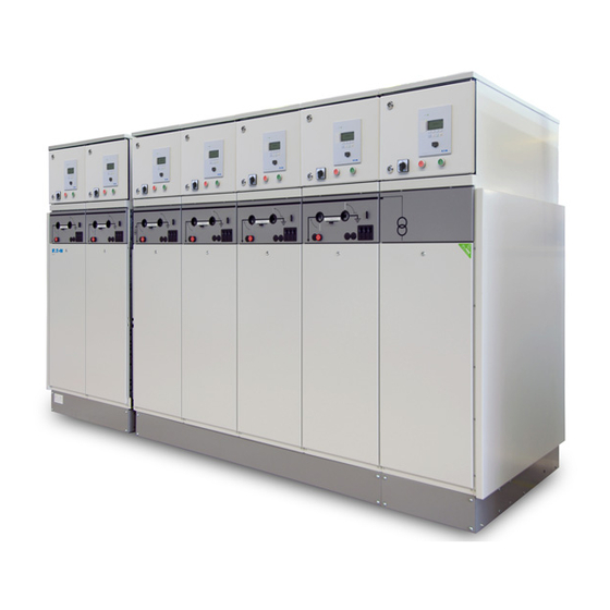
Medium-voltage switchgear
SVS/12
User manual 994.530 G01 02
Operations consisting of installing, connecting, operating, checking, commissioning, decommissioning and
maintaining medium-voltage switchgear of the SVS/12 type must only be carried out by authorised
personnel.
User Manual
Medium-voltage switchgear
SVS/12
994.530 G01 02
Eaton Electric B.V.
P.O. box 23, 7550 AA Hengelo, The Netherlands
tel:
+31 74 246 91 11
fax:
+31 74 246 44 44
e-mail:
holec-info@eaton.com
internet:
www.eatonelectrical.nl
in the event of failure
Eaton-Electrical Services & Systems : tel: +31 74 246 68 88
Advertisement

Related Manuals for Eaton SVS/12


Summary of Contents for Eaton SVS/12
- Page 1 Eaton-Electrical Services & Systems : tel: +31 74 246 68 88 Operations consisting of installing, connecting, operating, checking, commissioning, decommissioning and maintaining medium-voltage switchgear of the SVS/12 type must only be carried out by authorised personnel.
- Page 2 Administrative data Issue number: G01 02 Date of issue: 10-06-2010 Language: English Checked by Position: Product Manager Name: Bert ter Hedde Date: 10-06-2010 Initials:...
- Page 3 SVS/12 CONTENTS INTRODUCTION ..................6 general system description .................. 6 1.1.1 Medium-voltage switchgear ..................6 1.1.2 Modular construction ....................6 1.1.3 Design ........................6 1.1.4 Operation ........................ 6 1.1.5 Separate compartment for secondary equipment ............. 6 Using this manual ....................7 1.2.1...
- Page 4 SVS/12 SETTING UP THE SYSTEM ..............33 Guidelines for the switchroom ................33 3.1.1 General ......................... 33 3.1.2 Ceiling ........................34 3.1.3 Floor ......................34 3.1.4 Ventilation ......................34 3.1.5 Heating ......................... 34 3.1.6 Storage conditions ....................34 Transport and assembly ..................35 3.2.1...
- Page 5 SVS/12 4.2.5 Operation of disconnector, 1250 A panels ............. 89 4.2.6 Voltage indication and phase comparison, 630 A and 1250 A panels..... 92 4.2.7 Padlock interlocks, 630 A and 1250 A panels ............92 4.2.8 Self-resetting indicators, 630 A panels ..............95 4.2.9...
- Page 6 SVS/12 is equipped with locked access doors. 1.1.2 Modular construction Materials The SVS/12 system is based on a modular concept. This In accordance with current requirements, all materials used means that any combination and sequence of panels is in the SVS/12 system are environment-friendly, not only possible.
- Page 7 1.2.1 Target group to operate and monitor the system independently. For The SVS/12 system is designed for use by personnel who that reason, these activities are described in detail. are expert or adequately trained in carrying out electrical operations. Such personnel include: authorised persons, ...
- Page 8 The height must be measured from the floor or from the platform in front of the switchgear. A.1 Safe Dimensions Earthed metal enclosure and full primary insulation For the dimensions of the SVS/12 system, see chapter 2.3. protect against electric shock Mechanical interlocks prevent unauthorised switching operations. ...
- Page 9 In electrical switchrooms, only materials belonging to SVS/12 medium-voltage switchgear should only be carried the installation set up in that room may be stored there. out by suitably qualified personnel. ...
- Page 10 SVS/12 Recommendation to the user: the user can compile these 1.3.3 Explanation of warnings and symbols items into a book. He must ensure that all authorised used personnel are aware of the existence and contents of this book. IFE HAZARD There is a direct threat to the life of the user and A.2 Operational instructions...
- Page 11 Technical specification A complete type plate is made up of a main type plate with supplementary type plates if required. The main type plate is headed with the Eaton logo and address. Main type plate Supplementary type plate for load-break switch (example) Supplementary type plate for circuit-breaker (example) 994.530 G01 02...
- Page 12 1.4.2 Radiation and noise emission 1.4.3 Heating element The SVS/12, as normally supplied, is suitable for use in Radiation power systems up to and including 12 kV under the For the vacuum interrupters installed in the SVS/12 system, conditions described in EN 62271-1.
- Page 13 SVS/12 2. SYSTEM DESCRIPTION 2.1 The system Panel types 630 A – 420 mm wide 2.1.1 Busbar connect ion panel Circuit -breaker Load-break sw it ch Load-break sw it ch/ panel panel f use panel maximum 12/24 kV Bus-sect ion panel w it h...
- Page 14 SVS/12 1. Installation comprising different panel types 630 A - 420 mm wide 1. Control panel of load-break switch or circuit-breaker panel 2. Control panel of bus-section panel 3. Control panel of load-break switch/fuse panel 4. Cable protection cover 5. Fuse protection cover 6.
- Page 15 SVS/12 Panel types, 1250 A – 630 mm wide 1.1.2 Busbar connect ion panel Busbar connect ion panel Circuit -breaker panel w it h disconnect or Bus-sect ion panel (1260 mm w ide) Volt age met ering panel 994.530 G01 02...
- Page 16 SVS/12 2. Installation comprising various panel types 1250 A - 630 mm wide 1. Control panel of circuit-breaker panel 2. Control panel of bus-section panel 3. Cable protection cover 4. Type plate per panel (inside door) 5. Instrument compartment (600 mm high) 6.
- Page 17 (figure 2) a terminal block with locked cable entry ports for Eaton Magnefix cable boxes (12 kV) (figure 3) three terminal blocks for cable socket connection (12 kV) for one cable per phase, see chapter 2.3.1, figure 3.
- Page 18 (figure 2) a terminal block with locked cable entry ports for Eaton Magnefix cable boxes (12 kV) (figure 3) three terminal blocks for cable socket connection (12 kV) for one cable per phase, see chapter 2.3.1, figure 3.
- Page 19 for 12 kV version (figure 1); cable connections for paper-insulated lead-covered cables and plastic- insulated cables via Eaton Magnefix cable boxes for 24 kV version (figure 2); cable connections for plastic-insulated cables directly under the fuses ...
- Page 20 three plug-in connection cones (24 kV) for two cables per phase (figure 2) a terminal block with locked cable entry ports for Eaton Magnefix cable boxes (12 kV) (figure 3) three terminal blocks for cable socket connection (12 kV) for one cable per phase, see chapter 2.3.1,...
- Page 21 SVS/12 2.2.5 Bus-section panel with load-break switch or circuit-breaker A bus-section panel (figure 1) includes the following principal components as standard: a busbar system a disconnector a load-break switch or a circuit-breaker an operating mechanism ...
- Page 22 SVS/12 2.2.6 Metering panel The busbar system may include a metering panel (figures 1 Voltage and 2) equipped with current and voltage transformers. A transformers metering panel is equipped as standard with: epoxy-resin-insulated voltage transformers The voltage transformers are connected - on the primary side -...
- Page 23 SVS/12 2.3 Description of panel types 1250 A 2.3.1 Circuit-breaker panel A circuit-breaker panel includes the following principal components as standard: a busbar system a disconnector a circuit-breaker one of four connection possibilities: three plug-in conicnection cones for one cable per phase (figure 1) ...
- Page 24 SVS/12 2.3.2 Busbar connection panel A busbar connection panel consists of a busbar system to which a cable can be directly connected. To this end the panel is equipped with one of four connection possibilities: three plug-in connection cones for one cable per phase (figure 1) ...
- Page 25 SVS/12 2.3.3 Bus-section panel A bus-section panel (figure 1) includes the following principal components as standard a busbar system two disconnectors a circuit-breaker bus connections (instead of cable connections) an operating mechanism a control panel...
- Page 26 SVS/12 2.3.4 Metering panel The busbar system may include a metering panel (figures 1 and 2) equipped with current and voltage transformers. A metering panel is equipped as standard with: epoxy-resin-insulated voltage transformers The voltage transformers are connected - on the primary side -...
- Page 27 SVS/12 2.4 Safety (system-specific) 2.4.1 Interlocks, 630 A panels Definitions Load-break switch/fuse panel Panel in the "operating position" means: On the load-break switch/fuse panel, access to the fuse the disconnector is in the busbar position and the load-...
- Page 28 SVS/12 2.4.2 Interlocks, 1250 A panels Definitions Bus-section panel Panel in the "operating position" means: On a bus-section panel, the circuit-breaker can be the disconnector is in the busbar position and the closed if one of the disconnectors is in the earthing circuit-breaker is closed position.
- Page 29 SVS/12 2.5 Technical data 2.5.1 Electrical data, 630 A panels type SVS/12 17.5 General Rated voltage (kV) 17.5 Withstand voltage (kV) Power frequency withstand voltage (kV) Rated frequency (Hz) Busbar system Rated normal current 1250 1250 1250 Rated short time withstand current 1 s/2.5 s...
- Page 30 SVS/12 2.5.2 Dimensions and weights, 630 A panels without instrument with instrument with instrument compartment compartment compartment (600 mm high) (400 mm high) Panel width (mm) Panel depth (mm) 1110 1110 1110 Panel height (mm) 1350 1950 1750 Weight per panel (kg) approx.
- Page 31 SVS/12 2.5.3 Electrical data, 1250 A panels type SVS/12 17.5 General Rated voltage (kV) 17.5 Withstand voltage (kV) Power frequency withstand voltage (kV) Rated frequency (Hz) Busbar system Rated normal current 1250 1250 1250 Rated short time withstand current 1.5 s/2,5 s...
- Page 32 SVS/12 2.5.4 Dimensions and weights, 1250 A panels without instrument with instrument with instrument compartment compartment compartment (600 mm high) (400 mm high) Panel width (mm) Panel depth (mm) 1110 1110 1110 Panel height (mm) 1350 1950 1750 Weight per panel (kg) approx.
- Page 33 SVS/12 Entrances 3. SETTING UP THE SYSTEM Entrances must be provided at suitable places to rooms in which switchgear is set up. These entrances must be at 3.1 Guidelines for the switchroom least 0.75 m wide and 2 m high.
- Page 34 SVS/12 3.1.2 Ceiling 3.1.4 Ventilation If the ceiling is prone to condensation, it is advisable to fit Avoid unwanted air circulation; make sure that doors close an additional ceiling made of, for example, hardboard properly. If the installation is set up near to heavy vehicular (Masonite).
- Page 35 The holes in the four lifting points can be sealed with the sealing caps supplied.. A packed SVS/12 installation can also be moved with the aid of a pallet truck or fork lift. The installation must be transported in the “operating position”...
- Page 36 Transport in switchroom SVS/12 installations can be placed in the switchroom by means of steel rollers. Trolleys from Eaton can also be used to move the installation on wheels. 3.2.4 Setting up the installation 1.
- Page 37 The safety regulations must be observed when connecting cables (see chapter 1.3). Different cable connections are available with SVS/12 switchgear. The following is an overview of connections on 630 A panels. See chapter 3.4 for connections on 1250 A panels.
- Page 38 SVS/12 LOAD SWITCH/SAFETY PANELS 12 kV 12 - 17.5 - 24 kV Panel equipped with: Panel equipped with: 12 kV connection points 24 kV direct below safety device connection below the holders moulded resin safety device holders with gaskets and cable...
- Page 39 (see chapter 4.2.7). If the cable supports in the panel do not fit the Operat ing cables being connected, suitable supports must mechanism be ordered from Eaton. Cont rol panel This is important, so as to guarantee that cables Connection...
- Page 40 4 mm If plugs without an earthed exterior are used, Eaton recommends placing an additional interlock on the protection cover, so that the cables are only accessible if the panel is safely switched to the earthing position (disconnector in the earthing position, load-break switch or circuit-breaker closed).
- Page 41 The cables must be terminated in accordance with the instructions of the cable manufacturer. For these panels, Eaton can also supply fully terminated plastic-insulated cables for operating voltages up to 24 kV. These cables are designed with a core cross-section of 16 and are obtainable in any length.
- Page 42 Connecting cables (for Eaton and non-Eaton cables) 4. Lead the three cables into the installation via the underside (from the cellar).
- Page 43 Ensure that the bending radius of the cable is at least that specified by the supplier. For Eaton transformer cables, the bending radius is 15 times the external diameter of the cable. 12. Earth the screening of the cables to the earth bar via the flexible earth connection.
- Page 44 SVS/12 3.3.3 Connection of plastic-insulated cables up to 120 mm Cu or Al with straight plug connectors to a 12 - 24 kV load- break switch/fuse panel General The panel is equipped with moulded-resin-insulated 24 kV connections under the fuseholders. Single-core plastic-...
- Page 45 Ensure that the bending radius of the cable is at least that specified by the supplier. For Eaton transformer cables, the bending radius is 15 times the external diameter of the cable. 4. Earth the cable sheath. Cable clamp 5.
- Page 46 SVS/12 3.3.4 Connection of paper-insulated lead- covered cables up to 70 mm Cu by means of grease-filled cable boxes General Paper-insulated lead-covered cables can be connected to load-break switch and circuit-breaker panels up to 12 kV and to load-break switch/fuse panels up to 12 kV. Load- break switch and circuit-breaker panels are equipped with a terminal block with locked cable entry ports.
- Page 47 SVS/12 4. Saw off the cable box in accordance with the diameter (d) measured across the lead sheath, see figure 3. Take into account that several layers of polyethylene tape are to be applied over the lead sheath. Deburr sharp edges.
- Page 48 SVS/12 10. Fix the cable in the cable clamp at the marked position, see figures 6 and 7. Tighten the cable block. Check that the cable lies straight under the connection. Remove any spacer from the support of the cable block.
- Page 49 SVS/12 14. Fasten the cable cores to the connection points with the cable core clamps, see figure 9. Make sure that the cable cores are correctly positioned in the clamps. This is where the associated cross-sectional area is stated (see detail).
- Page 50 polyethylene tape For cables with an aluminium core (figure 3): Eaton cable core clamps are only suitable for connecting cables with a copper core. There is a maximum free space measuring Ø 40 x 85 mm for connecting cables with an aluminium core by means of crimp cable sockets, for instance.
- Page 51 SVS/12 Procedure 1. Attach the cable box to the cable, following the procedure described in chapter 3.3.4, steps 1-13. 2. Fit the connecting pieces to the connection pins using one of the washers: Tighten the hexagon socket head screws (torque 15 Nm).
- Page 52 SVS/12 7. Hang a double folded nylon thread over the edge of each opening in the cable box, with the ends hanging inside, see figure 3. Now slide the cable box completely on to the cast resin insulation.
- Page 53 (core diameter > 70 mm2 EMARK For cables with an aluminium core (figure 3): Eaton cable core clamps are only suitable for connecting cables with a copper core. There is a maximum free space measuring Ø 40 x 110 mm for connecting cables with an aluminium core by means of crimp cable sockets, for instance.
- Page 54 SVS/12 ROCEDURE L1 = 650 1. Remove the floor plate with the rubber grommet. 2. Cut the cable as shown in figure 1: L1 = 650 mm L2 = 175 EMARK To simplify insertion of the cable cores in the right tubes of the cable box, it is recommended to cut the cable cores to different lengths.
- Page 55 SVS/12 10. Remove the cable box from the cable terminal block. 11. Slide the cable box as far as possible on to the cable. Make sure the paper insulation of the cable cores does not get damaged. 12. Fix the cable in the cable clamp at the marked position, see figures 5 and 6.
- Page 56 polyethylene tape For cables with an aluminium core (figure 3): Eaton cable core clamps are only suitable for connecting cables with a copper core. There is a maximum free space measuring Ø 40 x 110 mm for connecting cables with an aluminium core by means of crimp cable d2 (core diameter >...
- Page 57 SVS/12 Procedure 1. Remove the floor plate with the rubber grommet. 2. Cut the cable as shown in figure 1. L1 = 650 mm EMARK L1=650 To simplify insertion of the cable cores in the right tubes of the cable box, it is recommended to cut the cable cores to different lengths.
- Page 58 SVS/12 8. Degrease the upper side of the lead sheath and sand it lightly, for example, with a Scotch Brite scouring pad. Apply a couple of layers of polyethylene tape to the lead sheath, so that the diameter measured across the tape equals the inside diameter of the plastic entry bushing, see figure 4.
- Page 59 SVS/12 13. Fix the cable in the cable clamp at the marked position, see figures 7 and 8. Move the distance piece until the centre of the cable is exactly in line with the centre of the cable box. Firmly tighten the cable clamp.
- Page 60 SVS/12 3.3.8 Filling the cable boxes Materials required (figure 1) a. Can of grease for the cable box: for small cable box: contents = for large cable box: contents = 2.25 for cable box with gland: ...
- Page 61 SVS/12 3. Secure the filling device by firmly tightening the screw in the top plate, see figure 3. Using the hose clip, firmly attach the hose to the filling tube of the filling device. 4. Remove the nylon locking pin and the rubber sealing from the cable box.
- Page 62 SVS/12 11. Remove the filling hose from the cable box once the grease in the cable box has cooled down and immediately put your thumb on the opening, see figure 6. This is necessary as the grease in the cable box is under pressure.
- Page 63 In that case, the protection cover must be fitted to ensure that the part above the guide cones is also insulated. Figure 1C shows a situation in which a cable termination is used without a guide cone. This situation arises, for example, with cables supplied by Eaton. 994.530 G01 02...
- Page 64 SVS/12 Required materials (figures 1 and 2) Three insulating conduits (a) One bag containing three greased rubber sleeves (b) Three sealing plugs (c) Two protection covers (d) Three guide cones (e) ( < 46 mm or > 46 mm) (figure 1) ...
- Page 65 SVS/12 2.2 “3 x 1-core cable” on cable panel, see figure 4 fasten the cable to the cable block drill 3 holes in the cable block (depending on the cable diameter) with their centres 54 mm apart. ...
- Page 66 SVS/12 3. Cut the cable cores 2 to 3 mm below the cast resin insulation. Remove the insulation of the cable cores over a distance of approximately 30 mm. 4. Make a hole suitable for the cable diameter in the grommets.
- Page 67 SVS/12 10. Fit both protection covers (d) and secure them. Make sure that the conduits adequately rest on the bearing faces of the protection covers, see figure 7. 11. Fit the sealing plugs. 12. Secure the floor plate. Place the grommet in the floor plate.
- Page 68 Figure 1C shows a situation in which a cable termination is used without a guide cone. This situation arises, for example, with cables supplied by Eaton. 994.530 G01 02...
- Page 69 SVS/12 Required materials (figure 2) Three insulating conduits (a) One bag containing three greased rubber sleeves (b) Three sealing plugs (c) Two protection covers (d) Three guide cones (e) ( < 46 mm or > 46 mm) (figure 1) ...
- Page 70 SVS/12 2.2 “3 x 1-core cable” on cable panel (figure 4) Fasten the cable to the wooden block (h) drill 3 holes in the cable block (depending on the cable diameter) with their centres 54 mm apart. ...
- Page 71 SVS/12 3. Cut the cable cores 2 to 3 mm below the cast resin insulation. Remove the insulation of the cable cores over a distance of approximately 30 mm. 4. Make a hole suitable for the cable diameter in the grommet.
- Page 72 SVS/12 10. Seal the openings of the cable box to prevent intrusion of dirt. connecting piece 11. Shorten the cable cores so that all three of them fit into the recesses in the connecting pieces. 12. Insert the rubber sleeves (b) previously greaseed with...
- Page 73 SVS/12 14. Slide the insulating conduits and the rubber sleeves on to the cast resin insulated members. Check that the flattened sides of the washers around the insulating conduits abut. 15. Fit both protection covers (d) and secure them. Make sure that the conduits adequately rest on the bearing faces of the protection covers.
- Page 74 SVS/12 3.3.11 Assembly of capacitive sensor Required accessories A voltage indicator on a 12 - 24 kV load-break switch/fuse panel is available as an option. This requires a capacitive sensor to be fitted on the non-cable side connection of the fuse box.
- Page 75 The safety regulations must be observed when connecting cables (see chapter 1.3). Different cable connections are available with SVS/12 switchgear. The following is an overview of connections on 1250 A panels. See chapter 3.3 for connections on 630 A panels.
- Page 76 (see chapter 4.2.7). If the cable supports in the panel do not fit the cables being connected, suitable supports must be ordered from Eaton. This is important, so as to guarantee that cables are securely fastened to the panel, also in case of a short-circuit current.
- Page 77 4 mm If plugs without an earthed exterior are used, Eaton recommends placing an additional interlock on the protection cover, so that the cables are only accessible if the panel is safely switched to the earthing position (disconnector in the earthing position, circuit-breaker closed).
- Page 78 SVS/12 3.4.2 Connection of plastic-insulated cables up to 630 mm2 Cu or Al via cable socket connection General Plastic-insulated cables can be connected to panels up to 12 kV. The panels are fitted with terminal blocks with locked cable entry ports. The terminal block has three terminal strips moulded into the cast resin insulation.
- Page 79 SVS/12 Required materials (figure 2) Three insulating conduits (a) consisting of a long part (a2) and a short part (a1) Two bags containing three greased rubber sleeves (b) Three sealing plugs (c) Three cable blocks (d) Procedure 1.
- Page 80 SVS/12 9. Lightly grease the cast resin insulation of the terminal blocks with acid-free Vaseline. 10. Fit three greased sleeves (b) on the terminal blocks. 11. Fix the cable sockets on the terminal blocks. 12. Slide the assembled insulating conduits over the cast resin insulation of the terminal blocks.
- Page 81 SVS/12 4. SYSTEM OPERATION 4.1 Who may operate the system? 4.1.1 Level of training Operational activities may only be carried out by or on the instructions of a responsible specialist or a control expert. 4.1.2 Operating conditions The operating conditions must not be different from the conditions described in chapter 3.1.1.
- Page 82 SVS/12 4.2 Operation 4.2.1 Control panels Control panels 630 A panels 1. Control panel of load-break switch or circuit-breaker panel 2. Control panel of load-break switch/fuse panel 1. Position indicator of load-break switch or circuit-breaker 7. Selector 2. Operating shaft of load-break switch or circuit-breaker 8.
- Page 83 SVS/12 3. Control panel of bus-section panel 1. Position indicator of load-break switch or circuit-breaker 2. Operating shaft of load-break switch or circuit-breaker 3. Operating shaft of disconnector 4. Position indicator of disconnector 6. Switch-off button of load-break switch or circuit-breaker 7.
- Page 84 SVS/12 Control panels 1250 A panels 1. Control panel of circuit-breaker panel 2. Control panel of bus-section panel 1. Position indicator of circuit-breaker 8. Voltage indicator 2. Operating shaft of circuit-breaker 9. Padlock interlock strip 11. Control knob to set disconnector to „busbar position‟...
- Page 85 SVS/12 4.2.2 Switching on and off, 630 A panels Mechanical switching on Mechanical switching off 1. Check by the position indicator (4) that the disconnector 1. Slide the selector (7) to the left. is fully in the busbar position or fully in the earthing 2.
- Page 86 SVS/12 4.2.3 Switching on and off, 1250 A panels Mechanical switching off Mechanical switching on 1. Check by the position indicator (4) that the disconnector 1. Firmly press the switch-off button (5). is fully in the busbar position or fully in the earthing The position indicator (1) should now indicate the off position.
- Page 87 SVS/12 4.2.4 Operation of disconnector, 630 A panels Description of disconnector The disconnector has two positions, the busbar position Eart h and the earthing position. busbar Switching from one position to the other is only possible if the load-break switch or circuit-...
- Page 88 SVS/12 Operating the disconnector, 630 A panels Control panel of load-break switch or icircuit-breaker panel. Interlocks The disconnector can only be operated if the load-break switch or circuit-breaker is open. Mechanical change-over from the busbar position to Mechanical change-over from the earthing position to...
- Page 89 SVS/12 4.2.5 Operation of disconnector, 1250 A panels Description of disconnector The disconnector has two positions, the busbar position Eart h busbar and the earthing position. Swit ch Switching from one position to the other is only connect ion possible if the circuit-breaker is open.
- Page 90 SVS/12 Operation of disconnector, 1250 A panels Control panel of circuit-breaker panel Interlocks Mechanical change-over from the earthing position to the busbar position The disconnector can only be operated if the circuit- breaker is open. 1. Switch off the circuit-breaker (see chapter 4.2.3).
- Page 91 SVS/12 Bus-section panel 1250 A The bus-section panel 1250 A with OCO mechanism (see 5. Check that busbar A in the relevant section A is dead chapter 4.2.3) has a busbar earthing facility; the bus- (see chapter 4.2.6). If there is no voltage indication on section panel 630 A does not have this.
- Page 92 SVS/12 4.2.6 Voltage indication and phase comparison, 630 A and 1250 A panels Voltage indicator A load-break switch, circuit breaker and busbar section Bus-section panel with load-break switch (630 A panel normally have a voltage indicator. As an option, a...
- Page 93 SVS/12 , 630 A 1250 A ITTING PADLOCK INTERLOCKS PANELS Locking in earthing position If the cable is earthed via the load-break switch or circuit- breaker, an interlock can be fitted to prevent switching off (figure 1). The procedure is as follows: 1.
- Page 94 SVS/12 PTION As an option, it is possible to have an arrangement whereby the protection cover can only be removed if the cable is earthed and the interlock strip is pulled out. In this case, the load-break switch can no longer be locked to prevent switching off in the operating position.
- Page 95 The signal-emitters should be red when the test and reset button is pressed. The signal-emitters should turn black when the test and reset button is pressed again. If the indicator is not working properly, the user should contact Eaton Service. 994.530 G01 02...
- Page 96 2. Fit the 3 contact pins and tighten them with a socket Use a polyamide thread for venting. wrench (size 13); the tightening torque is 9 Nm. The sleeves, end caps and polyamide thread are obtainable from Eaton. Remove the polyamide thread. 4. Fit the protection cover.
- Page 97 SVS/12 1250 A PANELS General As an option, 3 cable side voltage transformers and/or overvoltage deflectors can be fitted in a circuit-breaker panel, see figure 1. The primary side of the voltage transformers is connected to the cable connection by means of a detachable epoxy resin insulated connector.
- Page 98 Fit new sleeves greased with silicone grease and then the end caps. Use a polyamide thread for venting. The sleeves, end caps and polyamide thread are obtainable from Eaton. Terminal block Remove the polyamide thread. 4. Fit the protection cover.
- Page 99 SVS/12 4.3 Earthing of cables 4.3.1 Earthing of the cable via the load-break switch or circuit-breaker, 630 A and 1250 A panels 1. Turn the load-break switch or circuit-breaker off (see chapter 4.2.2 / 4.2.3). 2. Set the disconnector to the earthing position (see chapter 4.2.4 / 4.2.5).
- Page 100 SVS/12 4.3.2 Earthing the cable of a 12 - 24 kV load- break switch/fuse panel, 630 A Required accessories Bag containing earthing equipment, consisting of (see figure 1): three earthing pins (a) with earth contact and earthing cable (25 mm ) with connecting clamp ...
- Page 101 SVS/12 Removal of earthing IFE HAZARD When removing the earthing pins, never place your hand between the red ring on the operating rod and the earthing pins or the stop. 1. Using the operating rod, remove the earthing pins from the socket contacts (figure 1).
- Page 102 SVS/12 4.3.3 Earthing the cable of a 12 kV load- break switch/fuse panel, 630 A Required accessories Bag containing earthing equipment, consisting of (see figure 1): three earthing pins (a) with earth contact and earthing cable (25 mm ) with connecting clamp ...
- Page 103 SVS/12 EMOVAL OF EARTHING IFE HAZARD When removing the earthing pins, never place your hand between the red ring on the operating rod and the earthing pins or the stop. 1. Using the operating rod, remove the earthing pins one by one from the socket contacts (figure 1).
- Page 104 SVS/12 4.3.4 Three-pole short-circuit-proof back-up earth, 630 A and 1250 A panels Required accessories For fitting a three-pole back-up earth on the 17.5 kV cable entry port, a bag of earthing equipment can be supplied (figure 1), consisting of: ...
- Page 105 SVS/12 4. Move the shutter of the cable entry port up. 5. Insert the unit in the cable entry port as far as the plastic rings (figure 3). 6. Then lock the unit by turning the two interlocks behind the posts of the cabinet and remove the key: ...
- Page 106 (20 mm ball) (see figures 2 and 3 for an example). The earth plate of the relevant SVS/12 panel has to have a 20 mm ball-head bolt connection (see figure 4 for an example).
- Page 107 SVS/12 NSTALLATION OF THE SINGLE POLE BACK UP EARTH IFE HAZARD When earthing the cable via the 17.5 kV cable terminal block in combination with a direct busbar connection, the shutter is secured in front of the cable entry ports. The contacts behind this shutter are directly connected to the main busbar system of the installation.
- Page 108 SVS/12 5. Fit the insulated locking plate and slide it onto the earthing pins as far as the plastic rings (figure 4). Make sure that the guide pins of the locking plate are situated on top, next to the shutter.
- Page 109 SVS/12 4.3.6 Replacing high-voltage fuses The fuses (in conformity with DIN 43625) should have a striker pin, to ensure correct automatic opening of the load-break switch. Always place the striker pin output in the handle. 1. Switch the load-break switch off (see chapter 4.2.2).
- Page 110 SVS/12 7. Replace the fuse in the handle. Inserting the fuse in the 12 kV handle Inserting the fuse in the 12 - 24 kV handle ARNING When fitting the fuse, do not rest the handle On a 12 - 24 kV version, when removing the fuse...
- Page 111 SVS/12 4.4 Metering and voltage testing Required accessories 4. Insert the pins in the cable entry port and connect the Metering and testing pins for the 12 - 17.5 kV cable metering or voltage testing equipment (figure 1). entry port.
- Page 112 SVS/12 4.4.2 Testing the cable using right-angle plugs, 630 A and 1250 A panels 1. Earth the cable via the integrated earthing of the load- break switch or circuit-breaker (see chapter 4.3.1). 2. Open the relevant protection cover by turning the key a quarter turn counterclockwise and remove the panel.
- Page 113 the phase sequence of the connected cables is IFE HAZARD correct. If an SVS/12 panel is commissioned without a the earth busbar is earthed. primary cable connected, the panel in question the lead sheath or earth screens are earthed.
- Page 114 The installation must be completely dead before be destroyed, re-used or disposed of in accordance with dismantling. the regulations and requirements currently in force. A list of the materials used is available from Eaton. Personal protection equipment Safety goggles ...
- Page 115 Open the door of the instrument compartment as adhered to. far as possible (150º). Eaton can undertake this work for you or, if desired, can Pull the inside rack out as far as possible and turn train your own personnel to carry out inspection and the front of it as far as possible to the right.
- Page 116 SVS/12 Front of the installation 1. Top view of mechanism compartment (630 A panels) A. The shaft for driving the disconnector. F. The shaft for driving the position indicator for the load- B. The shaft for driving the load-break switch or circuit- break switch or circuit- breaker.
- Page 117 SVS/12 2. Top view of mechanism compartment (1250 A panels) A. Hinge points of the position indicator F. Gear wheels of right-angle transmission B. Hinge points of the interlock G. Hinge points of position indicator C. Pins of the on-off pushbutton H.
- Page 118 MAC 05 is a cleaning and conditioning agent If it is difficult to slide down because the grease has developed by Eaton which gets rid of surface become too viscous, you may heat the cable box a dirt and creates a moisture-repellent film of little, using a hair drier for instance.
- Page 119 SVS/12 6.1.5 Changing the bottom contacts in the 24 kV fuse holder of a load-break switch/fuse panel, 630 A General The 24 kV fuse holders of a load-break switch/fuse panel are suitable for use with 20/24 kV fuses (figure 1) in conformity with DIN 43625.
- Page 120 SVS/12 10/12 HANGING A BOTTOM CONTACT WITH 20/24 , 630 A SPACER FOR A BOTTOM CONTACT 1. Remove the high-voltage fuses according to the procedure described in chapter 4.3.6. In this situation the disconnector is in the earthing position and the load-break switch cannot be turned on.
- Page 121 SVS/12 20/24 HANGING A BOTTOM CONTACT FOR A 10/12 , 630 A BOTTOM CONTACT WITH SPACER 1. Remove the high-voltage fuses according to the procedure described in chapter 4.3.6. In this situation the disconnector is in the earthing position and the load-break switch cannot be turned on.
- Page 122 SVS/12 6.2 Repair Eaton Electrical Services & Systems (E_ESS) should be contacted for troubleshooting and repairs. E_ESS is available for advice and repair work 24 hours a day, 7 days a week. Address: B.V. ATON LECTRIC Eaton-Electrical Services & Systems (E_ESS) 7550 AA HENGELO, P.O.
- Page 123 SVS/12 7. ACCESSORIES 7.1 List of available accessories 1. Operating handle 2. Key for protection cover 3. Lifting eyes, cover caps and nylon washers 4. Key for cable core clamps 994.530 G01 02...
- Page 124 SVS/12 5. Filling device with: hand pump filling hose with hose clip, shut-off ring and connector nipple filling device with filling tube 6. Single-core Eaton plastic transformer cable; specify length and type when ordering 994.530 G01 02...
- Page 125 SVS/12 7. Earthing equipment for earthing the cable of a 12 - 24 kV load-break switch/fuse panel: three earthing pins with earth contact and earthing cable with clamps an operating rod Technical data Rated voltage (IEC) (kV) 17.5...
- Page 126 SVS/12 9. Three-pole, short-circuit-proof back-up earth to be installed on the 12 - 17.5 kV cable entry port of a load- break switch or circuit-breaker panel, consisting of: a three-phase star point with: three earth contacts one earthing cable ...
- Page 127 SVS/12 Accessories for single-pole short-circuit-proof back-up earth. 11.1 Earthing cable with ball-head bolt connector for single-pole short-circuit-proof back-up earth. 11.1 11.2 11.2 Mounting rod for earthing cables Technical data Rated voltage (IEC) (kV) 17.5 Rated short-time withstand current for 1 sec...
- Page 128 SVS/12 14. Metering and testing pins for 12 - 17.5 kV cable terminal block. Metering and testing pins for right-angle plugs (on request). 994.530 G01 02...
- Page 129 SVS/12 15. Single-pole voltage tester type UNL The single-pole voltage tester (type UNL) consists of two parts: the probe (antenna) with exchangeable test point; the grip. The probe is screwed onto the grip before use. During transport of the tester the probe can also be fixed to the grip in inverted position.
- Page 130 See EN 50110-1 § 4.4 for additional Supplier: requirements. Instruction Eaton Electric B.V. or its representative. User: All personnel involved in operations carried out on, with or near electrical installations must have been The person or body responsible instructed (using these operating instructions) for operation and maintenance of the switchgear.
- Page 131 SVS/12 8.2 Abnormal 8.3 Equipment and the area surrounding it Operating conditions Electrical installation Rated voltage, current, power An assembly of electrical leads and the appliances to The voltage, current and power upon which the design which the leads are connected.
- Page 132 data such as type, ratings, price, stock number or other order information User manuals: User manual for the Eaton equipment used in the relevant version(s). 994.530 G01 02...
- Page 133 SVS/12 9.2 Voltage detecting system Wega 1.2 994.530 G01 02...
- Page 134 SVS/12 994.530 G01 02...
- Page 135 SVS/12 994.530 G01 02...
- Page 136 SVS/12 994.530 G01 02...
- Page 137 SVS/12 9.3 Phase monitor Orion 3.0 994.530 G01 02...
- Page 138 SVS/12 994.530 G01 02...
Need help?
Do you have a question about the SVS/12 and is the answer not in the manual?
Questions and answers