Table of Contents
Advertisement
Quick Links
OPERATING MANUAL
(original operating manual)
INTILION scalebloc 0.5C
INTILION GmbH
Dr.-Sinsteden-Straße 8
D-08056 Zwickau
Telephone +49 (0) 375 270 550 0
Fax
+49 (0) 375 270 550 300
E-mail
contact@intilion.com
Internet
www.intilion.com
Store for future use!
6140203057 - operating manual scalebloc V1.0 DE
Advertisement
Table of Contents

Related Manuals for INTILION scalebloc 0.5C

Summary of Contents for INTILION scalebloc 0.5C
- Page 1 OPERATING MANUAL (original operating manual) INTILION scalebloc 0.5C INTILION GmbH Dr.-Sinsteden-Straße 8 D-08056 Zwickau Telephone +49 (0) 375 270 550 0 +49 (0) 375 270 550 300 E-mail contact@intilion.com Internet www.intilion.com Store for future use! 6140203057 - operating manual scalebloc V1.0 DE...
- Page 2 2019 Version 01 Edition: December 2019 © INTILION GmbH This operating manual and all of the illustrations contained within are copyright-protected. Any use that goes beyond the limits of copyright law without the prior written consent of the publisher is impermissible and punishable by law.
-
Page 3: Table Of Contents
3.2.4 Safety devices ......................38 3.2.4.1 Smoke detector ..................38 3.2.4.2 Door contact switch ................... 38 3.2.4.3 Alarm ......................39 3.2.4.4 Emergency stop contacts ................39 3.2.4.5 Fire-protection module ................40 3.2.4.6 Smoke degasification duct ................ 40 INTILION scalebloc 0.5C... - Page 4 Contents 3.2.5 Operating modes ..................... 40 Technical specifications ......................41 3.3.1 Battery storage system INTILION scalebloc 0.5C ........... 41 3.3.2 Lithium-ion batteries ....................42 Information regarding hazards during installation ..............45 Selecting the installation site ....................46 Preparatory measures ......................48 Disassembling the transport pallet ..................
- Page 5 10.2.2.6 Disassembling the cables for the lithium-ion batteries ......112 10.2.2.7 Removing the lithium-ion batteries ............113 10.2.2.8 Removing the earthing points ..............114 10.2.2.9 Preparing the battery storage system for loading ........115 10.2.2.10 Loading the battery storage system ............ 116 10.3 Disposal ..........................118 INTILION scalebloc 0.5C...
- Page 6 Illustration 2: Functional elements - view with open door ..............35 Illustration 3: Safety devices ........................36 Illustration 4: Type plate - attachment location ..................37 Illustration 5: Type plate - INTILION scalebloc 0.5C ................37 Illustration 6: Smoke detector ........................ 38 Illustration 7: Door contact switch ......................38 Illustration 8: Alarm ..........................
- Page 7 Illustration 53: INTILION configuration interface ................... 88 Illustration 54: INTILION configuration interface - enlarged ..............89 Illustration 55: INTILION – interface for optimisation of energy consumption ........90 Illustration 56: INTILION – interface for peak shaving ................91 Illustration 57: INTILION – interface for E-mobility ................91 Illustration 58: INTILION –...
- Page 8 Tables Tables Tab. 1: Training ............................18 Tab. 2: Technical specifications – battery storage system INTILION scalebloc 0.5C ......41 Tab. 3: Technical specifications – lithium-ion batteries ................. 42 Tab. 4: Maintenance intervals ......................102 INTILION GmbH...
- Page 9 Introduction Thank you for choosing an INTILION GmbH product. As part of the HOPPECKE Group, INTILION GmbH stands for high-quality storage solutions. This operating manual provides all of the information needed for smooth operation of the INTILION scalebloc 0.5C battery storage system (hereinafter referred to as the battery storage system).
-
Page 10: Means Of Representation
CAUTION Hazard with a low level of risk that, if not avoided, can lead to minor or moderate bodily injury. NOTE Hazard with a low level of risk that, if not avoided, can lead to material damage. INTILION GmbH... -
Page 11: Incorporated Warnings
Text in quotation marks constitutes references to other chapters or sections. 1.1.4 Symbols used in this manual Particular hazards are indicated as follows in the form of warnings: Warning of dangerous electrical voltage This symbol warns of danger from electrical energy. INTILION scalebloc 0.5C... -
Page 12: Warranty And Liability
Structural modifications to the battery storage system (conversions or other changes to the battery storage system must not be made without the prior written approval of INTILION GmbH. The battery storage system will lose its EU conformity in the event of any infringements) –... -
Page 13: Performance Guarantee
The performance guarantee can be ordered as an optional extra, and the contract is concluded with INTILION GmbH. With the conclusion of this contract, INTILION GmbH guarantees that the remaining useful battery capacity does not fall below a relative minimum value for the specified battery capacity. -
Page 14: Copyright Protection
Infringements will lead to liability for damages. The right to make any further claims remains reserved. Service/customer service INTILION GmbH is part of the HOPPECKE Group. Our customer service team is available to provide you with any technical information you may require:... -
Page 15: Intended Use
Intended use The operational safety of the battery storage system is only guaranteed if it is used as intended. The INTILION scalebloc 0.5C is an AC-coupled battery storage system and is only suitable for the following application: Behind-the-meter application There are three important features that are worth mentioning for the behind-the-meter field of application: The system interacts with the energy meter at the operating company’s mains... -
Page 16: Structural Changes To The Battery Storage System
Parts and special equipment that are not supplied by INTILION GmbH are not approved for use on the battery storage system. -
Page 17: Foreseeable Misuse
Do not overcharge or deep discharge the lithium-ion batteries. – Avoid excessive charge rates and charge currents. – Avoid short circuits. – Do not operate the battery storage system in a potentially explosive environment. – Only operate the battery storage system in intended networks. INTILION scalebloc 0.5C... -
Page 18: Personnel Requirements
These persons must have completed an INTILION scalebloc product training session and must be familiar with and act in accordance with the operating manual. The relevant authorisations of the various personnel must be clearly defined. -
Page 19: Responsibilities
– Keep unauthorised persons away from the working area. – If in doubt, approach persons in the working area and escort them out if necessary. – Stop work if there are unauthorised persons in the working area. INTILION scalebloc 0.5C... -
Page 20: Training
Keep all safety instructions and warnings on the product in a legible condition and replace them if necessary. – Operation of and work on the battery storage system must only be performed by trained and qualified personnel (see “2.2 Personnel requirements”). INTILION GmbH... -
Page 21: Safety Measures For Environmental Protection
Take the battery storage system out of operation immediately in the event of malfunctions. Have the malfunctions rectified by appropriately trained specialists or by INTILION GmbH or the HOPPECKE Service team. – Always store the operating manual in the location where the battery storage system is used. -
Page 22: Special Warnings
This symbol prohibits fire, open flame and smoking. Observe manual This symbol stipulates the observance of the manuals and the safety instructions. Keep all safety instructions and warnings on the battery storage system in a legible condition. Replace the warnings as necessary. INTILION GmbH... -
Page 23: Danger Due To Electrical Energy
(connections P+ and P-) on the mains side. The individual lithium-ion batteries cannot be de-energised. There is always dangerous electrical voltage at the power connections on the lithium-ion batteries and at the connections B+ and B- on the battery management system. INTILION scalebloc 0.5C... - Page 24 Work on the electrical equipment must only be performed by a responsible specialised electrician (e.g. industrial electrician) with WLE certification. The responsible specialist electrician must have completed an INTILION scalebloc product training session. Always used isolated tools (up to 1000 V) when working.
-
Page 25: Dangers Due To Lithium-Ion Batteries
Use warning signs to mark and secure the storage location. Have the lithium-ion batteries disposed of by a certified specialist company or by INTILION GmbH (see Section “10 Decommissioning and disassembly”). INTILION scalebloc 0.5C... -
Page 26: Dangers Due To Hot Surfaces
If a harness is used as fall protection: Observe the rescue concept for people in harnesses. A person must not be left suspended in a harness for more than 15 minutes, as otherwise they could go into shock, with potentially fatal consequences. – Qualification for working at heights must be demonstrated. INTILION GmbH... -
Page 27: Dangers Due To Noise
– Only use original spare parts. – Procure spare parts from INTILION GmbH. The necessary information regarding spare parts can be found in the enclosed parts lists or in “1.5 Service/customer service“. Personal protective equipment Irrespective of the workplace risk assessment, personal protective equipment must be worn when operating the battery storage system in order to keep health risks to a minimum. - Page 28 Personal protective equipment must be provided by the operating company and must comply with the applicable requirements. The national regulations and specifications from the workplace risk assessment must also be observed, along with any internal instructions from the operating company. INTILION GmbH...
-
Page 29: Safety And Protective Devices
In the event of personal injury, inform the first-aid officer and an emergency doctor or the emergency services immediately. – Clear the access routes for rescue vehicles. If necessary, assign somebody with the task of briefing the emergency services. INTILION scalebloc 0.5C... -
Page 30: Obligations Of The Operating Company
The following rules apply in this regard: – The operating company must ensure that the maintenance intervals specified in this operating manual are complied with. – The operating company must have all safety devices checked for correct functioning and completeness on a regular basis. INTILION GmbH... - Page 31 2 Safety 2.9 Obligations of the operating company – The operating company must perform regular checks to establish that all of the safety instructions and warnings attached to the battery storage system are legible and permanently affixed. INTILION scalebloc 0.5C...
-
Page 32: Obligations Of The System Manager
– The system manager must have read and understand the operating manual. He or she must consult the HOPPECKE Service Competence Center in the event of misunderstandings. INTILION GmbH... - Page 33 2 Safety 2.10 Obligations of the system manager INTILION scalebloc 0.5C...
-
Page 35: Functional Description
Description of the battery storage system Functional description The INTILION scalebloc 0.5C is an AC-coupled battery storage system for use in industrial applications. The battery storage system features lithium-ion batteries with an overall capacity of 68.5 kWh and a 30 kVA inverter. -
Page 36: Overview
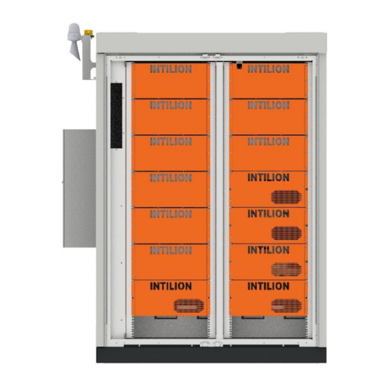
3 Description of the battery storage system 3.2 Overview Overview 3.2.1 Overview of functional elements View with closed door Illustration 1: Functional elements - view with closed door 1 LTE antenna 3 Door 2 AC unit 4 Outdoor housing IP55 INTILION GmbH... -
Page 37: Illustration 2: Functional Elements - View With Open Door
3 Description of the battery storage system 3.2 Overview View with open door Illustration 2: Functional elements - view with open door 1 Lithium-ion battery 5 Battery management system (BMS) 2 Socket 6 Inverter 3 Installation area 7 ControlShield 4 Temperature sensor PT1000 INTILION scalebloc 0.5C... -
Page 38: Overview Of Safety Devices
Illustration 3: Safety devices 4 Smoke degasification duct (see “3.2.4.6 1 Visual and acoustic alarm Smoke degasification duct”). 2 Smoke detector 5 Door contact switch 3 Fire-protection module 6 ControlShield EMERGENCY STOP CONTACTS (option of integration into the emergency stop circuit) INTILION GmbH... -
Page 39: Type Plate
Rated current (max): 50 A Weight: 950 kg Installed power: 30 kVA Dimension (W/D/H): 1618/1026/2030 mm Installed capacity: 68.5 kWh Material number: 0123456789 Serial number: 123456789123456789 Construction date: 01.04.2019 Illustration 5: Type plate - INTILION scalebloc 0.5C INTILION scalebloc 0.5C... -
Page 40: Safety Devices
If the doors are closed again, a system reset will need to be performed. The reset will re- activate the AC unit and start up the system. The reset procedure is described in Section 7 - “Operation”. INTILION GmbH... -
Page 41: Alarm
If this circuit is interrupted, the battery storage system will be disconnected from the network by an integrated circuit breaker. If this disconnection is not desired, the corresponding terminals will need to be bridged. These bridges are factory-fitted as standard. Illustration 9: Emergency stop contacts INTILION scalebloc 0.5C... -
Page 42: Fire-Protection Module
Surrounding lithium-ion batteries are protected against propagation 3.2.4.6 Smoke degasification duct The smoke degasification duct is intended for the indoor version. Always consult INTILION GmbH before performing indoor installation. WARNING Risk of injury! The targeted removal of smoke gases by the smoke degasification duct is mandatory when the battery storage system is installed inside buildings. -
Page 43: Technical Specifications
L Ambient conditions at the installation site Ambient temperature during -30 °C to +50 °C operation (permissible) Air humidity, non-condensing 95 % rel. humidity (max. permissible) Tab. 2: Technical specifications – battery storage system INTILION scalebloc 0.5C INTILION scalebloc 0.5C... -
Page 44: Lithium-Ion Batteries
Capacity (nominal) 94 Ah Voltage (nominal) 3.68 V Voltage range 2.7 V - 4.15 V Weight 2.1 kg Dimensions (W x H x D) 173 mm x 125 mm x 45 mm Tab. 3: Technical specifications – lithium-ion batteries INTILION GmbH... - Page 45 3.3 Technical specifications Transport and storage The battery storage system is transported in accordance with the specifications and under the supervision of INTILION GmbH or by INTILION GmbH or by personnel who have been trained and assigned by a distribution partner. NOTE...
- Page 46 4 Transport and storage 3.3 Technical specifications INTILION GmbH...
-
Page 47: Information Regarding Hazards During Installation
Installation The battery storage system is installed in accordance with the specifications and under the supervision of INTILION GmbH or by INTILION GmbH or by personnel who have been trained and assigned by a distribution partner. Always consult INTILION GmbH before performing indoor installation. -
Page 48: Selecting The Installation Site
Keep unauthorised persons away from the area. • Appoint a responsible person. • Lay power-supply cables so that they do not constitute a trip hazard or impair accessibility (e.g. in cable channels). • Mark any unavoidable trip hazards. INTILION GmbH... -
Page 49: Illustration 10: Maintenance Areas
The foundation must have a load-bearing capacity of at least 1 t/m². The operating company is responsible for the static properties of the foundation. Please contact INTILION GmbH or a distribution partner for information regarding the foundation specifications. INTILION scalebloc 0.5C... -
Page 50: Preparatory Measures
The battery storage system is delivered on a transport pallet. The fixing screws must be removed prior to unloading. Illustration 11: Disassembling the transport pallet - removing the fixing screws • Remove the fixing screw (1) at each corner. INTILION GmbH... -
Page 51: Illustration 12: Disassembling The Transport Pallet - Removing The Floor Plates
If present, remove the floor plates (1) to (5). There are two floor plates (1) and (2) on the AC unit side. There are three floor plates (3) to (5) on the opposite side to the AC unit. INTILION scalebloc 0.5C... -
Page 52: Positioning The Battery Storage System Onto The Foundation And Securing In Place
The following illustration shows the technical drawing of the base. This drawing can be used to ascertain the drill measurements for the attachment of the anchors (slots). A base template can be requested from INTILION GmbH to help with assembly. Illustration 13: Technical drawing of the base... -
Page 53: Safety
If this is not possible, take the necessary precautions in order to rule out damage to the battery storage system. Adjust the length of the carrying aids so as to ensure that the battery storage system can be transported horizontally. INTILION scalebloc 0.5C... -
Page 54: Attachment Points
Illustration 14: Overview of the attachment points 1 Attachment points (4 points) Illustration 15: Removing the covers over the attachment points • If present, remove the covers over the attachment points (1) and attach the shackle or hook. INTILION GmbH... -
Page 55: Unloading And Positioning The Battery Storage System And Securing In Place
With an M10 thread, the tightening torque must be at least 45 Nm. • Follow these steps in reverse order to secure the floor plates. It helps to initially leave the floor plate with Icotek frame disassembled, and to only install it once the ControlShield has been connected. INTILION scalebloc 0.5C... -
Page 56: Earthing The Battery Storage System
(1) on the battery storage system. Illustration 17: Securing the earthing system for rack rails • Secure the earthing system for the rack rails at position (1). To do so, pull the earthing cable through the opening in the floor plate. INTILION GmbH... -
Page 57: Inserting The Lithium-Ion Batteries
Carry the load as close to your body as possible. • Carry loads at the centre of your body or split between the two sides of your body. • Carry any heavy, unwieldy or bulky loads in pairs. INTILION scalebloc 0.5C... -
Page 58: Illustration 18: Lithium-Ion Batteries - Delivery Condition
Each lithium-ion battery is protected by dampening cardboard and a film. Illustration 19: Lithium-ion batteries - opening the box • Carefully open the box by pulling the adhesive strips, and fold open the flaps. • Remove the film and the cardboard. INTILION GmbH... -
Page 59: Illustration 20: Lithium-Ion Batteries - Removing From The Box
If this occurs, keep your distance from the lithium-ion battery and observe Section “2.5.3 Dangers due to lithium-ion batteries”. • Contact the Hoppecke Service Competence Center (see Section “1.5 Service/customer service”). • The affected lithium-ion batteries must not be used under any circumstances. INTILION scalebloc 0.5C... -
Page 60: Illustration 21: Lithium-Ion Batteries - Securing To The Fire-Protection Module
16 digits and are located on the front of the lithium-ion batteries and on the associated boxes. • Inform INTILION GmbH of the serial numbers; these are required for monitoring purposes and for service support via the HOPPECKE cloud solution. Start by inserting all lithium-ion batteries and screwing them in place before carrying out any wiring work. -
Page 61: Power Cabling Of The Lithium-Ion Batteries
VDE 0105-100 Section 6.3.2 • For safety reasons (among others), installation is prohibited without valid training by INTILION GmbH. • Wear arc-proof work clothing, 1000V protective gloves, safety boots and a safety helmet with visor to protect against arcs. The visor must be kept closed at all times when carrying out subsequent work. -
Page 62: Illustration 22: Lithium-Ion Batteries - Removing The Safety Caps
Illustration 22: Lithium-ion batteries – removing the safety caps • Push the safety caps on the poles (1) upwards (2), and remove in the direction of the arrow (3). INTILION GmbH... -
Page 63: Illustration 23: Wiring Diagram
(-) of battery module 4 (Bat 4). • Put the safety caps back on. • Connect the cable with the 3+ marking shown in blue in the diagram to the positive pole (+) of battery module 3 (Bat 3). INTILION scalebloc 0.5C... -
Page 64: Illustration 24: Laying The Cell Connectors
Put the safety caps back on. • Use the 560-mm-long cell connector to connect the positive pole (+) of battery module 8 to the negative pole (-) of battery module 9. • Put the safety caps back on. INTILION GmbH... - Page 65 No control cable is connected to the output side of battery module 9 (connections COMM OUT and FAN PWR (right)). There is a blank plug in the recess in the cover (see 5.10 “Connecting the communication, control and power cables”). INTILION scalebloc 0.5C...
-
Page 66: Installing The Panels For The Fire-Protection Modules
(Icotek grommet with no hole) for the unoccupied recess in the panel. This grommet is included with the delivery of the INTILION scalebloc. • Place the Icotek grommets KT13 or KT8 around the corresponding cables. -
Page 67: Illustration 27: Inserting The Icotek Grommets Into The Panel For The Fire-Protection Modules
The flat side of the Icotek grommets must be pressing against the fire-protection module. Illustration 28: Securing the panel for the fire-protection modules • Attach the panel to the fire-protection module with six screws (1). Tighten the screws to a tightening torque of 5 Nm. INTILION scalebloc 0.5C... - Page 68 5 Installation 5.9 Installing the panels for the fire-protection modules • Make sure that the panel is flush. This is essential for the correct functioning of the fire-protection concept. INTILION GmbH...
-
Page 69: Connecting The Communication, Control And Power Cables
Icotek frame and the correct Icotek grommet. • Disassemble the Icotek frame from the floor plate. • Place the suitable Icotek grommets around the corresponding cables. An Icotek grommet is suitable if it closes with a little pressure (see following illustration). INTILION scalebloc 0.5C... -
Page 70: Illustration 30: Icotek Grommet - Suitable For Cable
Illustration 31: Icotek grommet - not suitable for cable • Thread the cable with Icotek grommet into the Icotek frame. • When doing so, make sure that the flat sides of the Icotek grommets are resting against one another INTILION GmbH... -
Page 71: Final Measures
Icotek frame and/or the Icotek grommets and whether all earthing cables have been connected. • Close the doors of the battery storage system. To this end, start by lifting up the respective latching hook. INTILION scalebloc 0.5C... -
Page 72: Illustration 33: Adjusting The Ac Unit
Adjust the setpoints to 23 °C for “Controls Condenser Blower & Compressor” (1) and to 16 °C for “Controls Heater” (2). The following illustrations show the positions of the adjustment elements in the AC unit: ° ° Illustration 33: Adjusting the AC unit INTILION GmbH... -
Page 73: Establishing The Mains Connection
A power and energy flow measurement at the main connection point is required for the applications (e.g. “Optimisation of energy consumption”). The entire energy requirements flow via the main connection points and are optimised by the relevant application. The following INTILION scalebloc 0.5C... -
Page 74: Illustration 35: Energy Meter Connection Diagram
Illustration 35: Energy meter connection diagram INTILION GmbH offers a range of different energy meters and transformers; for more information, please contact either your contact partner or the HOPPECKE Service team. -
Page 75: Illustration 37: Diagram Showing The Connection Of Multiple Battery Storage Systems
A separate connection document is available in relation to this. The Ethernet or network cable (red) connects the Master to the energy meter and the Slave. The Ethernet ports -XF14 and -XF15 are provided for this purpose. INTILION scalebloc 0.5C... -
Page 76: Illustration 38: Ethernet Ports For Connecting The Energy Meter And The Battery Storage System
Illustration 38: Ethernet ports for connecting the energy meter and the battery storage system Either the previous battery storage system or the energy meter (in the event of the Master) is connected to port -XF14. The next battery storage system is connected to port -XF15. INTILION GmbH... - Page 77 5 Installation 5.12 Establishing the mains connection INTILION scalebloc 0.5C...
- Page 79 Following initial commissioning, the “System management” document must be signed in duplicate. One copy is kept by INTILION GmbH and the second copy is stored in the battery storage system. For re-commissionings, contact INTILION GmbH (see Section “1.5 Service/customer service”).
-
Page 80: Preparatory Work And Information
If there is subsequent reference to a change to the network address, the network settings or the ID address space, this relates to the configuration described here. The subnet mask is always 255.255.255.0 INTILION scalebloc 0.5C... -
Page 81: Illustration 39: Control Panel Overview Screen In Windows 10
The following numbers are blocked as IP addresses: 10 to 29 reserved for control units 30 to 49 reserved for converters 50 to 69 reserved for the BMS reserved for energy meters Illustration 39: Control panel overview screen in Windows 10 INTILION scalebloc 0.5C... -
Page 82: Illustration 40: Network And Internet Section Of The Control Panel
6 Commissioning 6.1 Preparatory work and information Illustration 40: Network and Internet section of the control panel Illustration 41: Network adapter settings INTILION GmbH... -
Page 83: Illustration 42: Options For The Network Adapter
6 Commissioning 6.1 Preparatory work and information Illustration 42: Options for the network adapter Illustration 43: Settings for the IP address, the standard gateway and the DNS server INTILION scalebloc 0.5C... -
Page 84: Commissioning The Energy Meter
Instructions on changing the IP settings in Windows 10 can be found in Section 6.1 “Preparatory work and information”. Instead of ending the IP address with 10, you can choose another whole number from 2 to 254 (apart from 20). INTILION GmbH... -
Page 85: Illustration 44: Configuration Software Ucs - Main Menu
Illustration 45: Configuration software UCS - setting the IP address for the energy meter • Tap on Modbus TCP and adjust the IP address for the energy meter • Tap on Connect. INTILION scalebloc 0.5C... -
Page 86: Illustration 46: Configuration Software Ucs - Selecting The Energy Meter
Illustration 46: Configuration software UCS - selecting the energy meter • Tap on the located energy meter An overview page will appear, containing information on the energy meter: Illustration 47: Configuration software UCS - overview page for the energy meter • Tap on S ETTINGS INTILION GmbH... -
Page 87: Illustration 48: Configuration Software Ucs - Entering The Transformer Ratio
. However, check to OLTAGE RANSFORMER ATIO make sure that the ratio is set to 1.0. Then open the page containing the network settings for the energy mete: Illustration 49: Configuration software UCS -- network settings for the energy meter INTILION scalebloc 0.5C... -
Page 88: Settings In The Web Visualisation
The IP address of your computer/laptop will need to be adjusted in order to access the web visualisation. The recommended settings are shown in the illustration below: IP address: 192.168.55.5 Subnet mask: 255.255.255.0 Standard gateway: 192.168.55.1 Preferred DNS server: 192.168.55.1 INTILION GmbH... -
Page 89: Illustration 50: Overview Of Recommended Settings
The computer/laptop can then be connected to ports -XF14 or -XF15 on the front of the ControlShield for commissioning. Enter the address “192.168.55.10/webvisu” in the web browser. The “INTILION web visualisation” will open (see illustration below). At the top right of the interface, there is the option to set the language to either German (DE) or English (EN). -
Page 90: Illustration 52: Intilion User Interface
Intilion The following user interface appears for the installation technician. Illustration 52: INTILION user interface The following interface can be opened by clicking on the “Configuration” icon (second from the left). All of the necessary configurations for the commissioning of the battery... -
Page 91: Illustration 54: Intilion Configuration Interface - Enlarged
6 Commissioning 6.3 Settings in the web visualisation Illustration 54: INTILION configuration interface - enlarged The following values should be entered in the “Setpoint” column of this table: 1. “Amount of scaleblocs”: The total number of installed battery storage systems connected to one another by a network cable is entered here. -
Page 92: Illustration 55: Intilion - Interface For Optimisation Of Energy Consumption
The threshold is therefore usually set to 0 kW. Illustration 55: INTILION – interface for optimisation of energy consumption “Peak shaving” application With this application, you will need to enter the threshold maintained by the battery storage system. -
Page 93: Illustration 56: Intilion - Interface For Peak Shaving
Illustration 56: INTILION – interface for peak shaving “E-mobility” application This application is project-specific and depends on the charging infrastructure and the charging station being used. This application should be clarified with INTILION. An individual assessment is always necessary here. Illustration 57: INTILION – interface for E-mobility Clicking on the Play icon adopts and saves all of the settings. -
Page 94: Illustration 58: Intilion - Interface For Entering The Serial Numbers
6 Commissioning 6.3 Settings in the web visualisation Illustration 58: INTILION – interface for entering the serial numbers The serial number for the scalebloc should already be entered – if this is not the case, it can be found on the type plate. Nine serial numbers for the modules also need to be entered for each scalebloc. -
Page 95: Filling In The Commissioning Log
Filling in the commissioning log Carry out additional tasks as per the commissioning log and make a note of the results. INTILION scalebloc 0.5C... -
Page 96: Installing The Panels For The Rest Of The Components
Contacting the Hoppecke Service team Once the steps listed in points 6.1 to 6.4 have been performed, please contact the HOPPECKE Service team. You will need to send them the completed commissioning log so that customer access can be set up. INTILION GmbH... - Page 97 6 Commissioning 6.8 Contacting the Hoppecke Service team INTILION GmbH is part of the HOPPECKE Group. Our customer service team is available to provide you with any technical information you may require: HOPPECKE Service Competence Center Tel: +49 (0) 800 246 77 32 (German)
- Page 98 6 Commissioning 6.8 Contacting the Hoppecke Service team INTILION GmbH...
- Page 99 Risk to health due to electromagnetic radiation! During operation, there is a risk to the health of persons with medical implants (e.g. pacemakers) as a result of electromagnetic radiation. – Persons with medical implants must not enter the battery storage system. INTILION scalebloc 0.5C...
- Page 101 Fault In the event of malfunctions, please contact INTILION GmbH via the HOPPECKE Service Competence Center (see Section “1.5 Service/customer service”). INTILION scalebloc 0.5C...
- Page 102 8 Fault INTILION GmbH...
-
Page 103: Safety Measures During Maintenance Work
Use a ladder if you cannot reach the assemblies/components requiring maintenance from the ground. Do not use a single ladder, and make sure that the ladder is securely in position. – Replace any assemblies/components that are not in perfect condition immediately. – Only use original spare parts. INTILION scalebloc 0.5C... -
Page 104: Inspection And Maintenance Work
Visual inspection 9.2.3.2 Update the As per description 9.2.3. displayed State of Health AC unit As per specifications 9.2.3. from INTILION GmbH Smoke detector As per supplier 9.2.3. specifications Doors As per description 9.2.3. Special maintenance intervals Electrical Safety inspection 9.2.4... -
Page 105: Preparatory Measures
Shut down the control unit for the system. • Make sure that the DC contactors are disconnected. • Make sure that the circuit breakers are disconnected. • Secure the circuit breakers against re-activation and shut down the circuit breaker. INTILION scalebloc 0.5C... -
Page 106: Maintenance - Annual
In order to ensure that the SoH measured and communicated by the battery management system is updated automatically, the battery storage system must initially be charged to a State of Charge (SoC) of 100%, and then discharged to a SoC of 5%. INTILION GmbH... -
Page 107: Ac Unit
9.2 Inspection and maintenance work 9.2.3.4 AC unit • Maintain the AC unit in accordance with the specifications from INTILION GmbH. Information on maintenance work to be performed on the AC unit can be found in the documentation from INTILION GmbH. 9.2.3.5 Smoke detector •... -
Page 108: Maintenance Of Additional Third-Party Components
If a software update is available, the system manager will be contacted by INTILION GmbH. A pre-defined time will be specified for the installation of the software updated. At this time, the system manager must be on site at the system, and must ensure that no switching operations are performed on site within the operating company’s... -
Page 109: Decommissioning
Make sure that the DC contactors are disconnected. • Make sure that the AC circuit breakers are disconnected. • Secure the AC circuit breakers against re-activation and shut down the circuit breaker. • Disconnect the battery storage system from the mains. INTILION scalebloc 0.5C... -
Page 110: Disassembly
Carry the load as close to your body as possible. • Carry loads at the centre of your body or split between the two sides of your body. • Carry any heavy, unwieldy or bulky loads in pairs. INTILION GmbH... -
Page 111: Disassembly Work
Push the front panel approx. 10 mm in the direction of the arrow and remove it. • Remove the side panels in the same way. To remove the side panels, push them forward towards the operating side. INTILION scalebloc 0.5C... -
Page 112: Disassembling The Communication, Control And Power Cables
• Disassemble the Icotek frame from the floor plate (3). • Undo the screws on the Icotek frame and remove the cables. • Remove the Icotek grommets from the cables. • Disassemble the communication, control and power cables. INTILION GmbH... -
Page 113: Disassembling The Panels For The Battery Management System (Bms) And The Inverter
The procedure for the disassembly of a panel is described below. Disassembly is performed in a similar way for the other panels. Illustration 64: Disassembling the panel for the fire-protection modules • Remove the screws (1) and remove the panel. • Repeat the procedure for all panels. INTILION scalebloc 0.5C... -
Page 114: Disassembling The Cables For The Lithium-Ion Batteries
Push the safety caps on the poles (1) upwards (2), and remove in the direction of the arrow (3). • Disassemble the cables. • Put the safety caps back onto the poles in reverse order. • Disassemble the cables in the same way for all other lithium-ion batteries. INTILION GmbH... -
Page 115: Removing The Lithium-Ion Batteries
Only ever lift the lithium-ion batteries with the assistance of a second person. Illustration 66: Lithium-ion batteries – disassembling from the fire-protection module • Remove the four screws (1) from each lithium-ion battery. • Remove the lithium-ion battery from the fire-protection module. INTILION scalebloc 0.5C... -
Page 116: Removing The Earthing Points
• Undo the earthing system for the rack rails at position (1). Illustration 68: Disassembling the foundation earthing system • Undo the foundation earthing system/designated earthing point in the foundation from position (1) on the battery storage system. INTILION GmbH... -
Page 117: Preparing The Battery Storage System For Loading
Insert the front panel and push it as far as it will go (approx. 10 mm) in the direction of the arrow. • Secure the front panel using the previously removed screws (1). • Close the doors of the battery storage system. To this end, start by lifting up the respective latching hook. INTILION scalebloc 0.5C... -
Page 118: 10.2.2.10 Loading The Battery Storage System
If this is not possible, take the necessary precautions in order to rule out damage to the battery storage system. Adjust the length of the carrying aids so as to ensure that the battery storage system can be transported horizontally. INTILION GmbH... -
Page 119: Illustration 70: Overview Of The Attachment Points
Illustration 70: Overview of the attachment points 1 Attachment points (4 points) Illustration 71: Removing the covers over the attachment points • Remove the covers over the attachment points (1) and attach the shackle or hook. INTILION scalebloc 0.5C... -
Page 120: Disposal
10.3 Disposal INTILION GmbH is obligated to take back the lithium-ion batteries. INTILION GmbH will happily prepare a quote for you for the disposal of your lithium-ion batteries. • Have the lithium-ion batteries disposed of by a certified specialist company or by INTILION GmbH. - Page 121 11 Applicable documents 10.3 Disposal Applicable documents The following documents are attached to this operating manual in the form of appendices: – EU Declaration of Conformity – Overview wiring diagram – Technical data sheet – Commissioning log INTILION scalebloc 0.5C...
Need help?
Do you have a question about the scalebloc 0.5C and is the answer not in the manual?
Questions and answers