Table of Contents
Advertisement
Quick Links
Advertisement
Table of Contents

Related Manuals for EXFO MaxTester 630G


Summary of Contents for EXFO MaxTester 630G
- Page 1 User Guide MaxTester 630G G.fast/VDSL2/ADSL2+ Multi-play Test Set...
- Page 2 EXFO Inc. (EXFO). Information provided by EXFO is believed to be accurate and reliable. However, no responsibility is assumed by EXFO for its use nor for any infringements of patents or other rights of third parties that may result from its use.
-
Page 3: Table Of Contents
Date and Time ........................25 Battery Info ...........................26 Software Options ........................28 Information ..........................30 Upload Setup ........................31 Wi-Fi Test ..........................39 EXFO Connect ........................41 Comms Setup ........................41 5 Setting Up DSL/IP Tests ................43 DSL Main Menu Page ......................43 Test Configuration ........................44 Test Setup ..........................58 Setup ............................75... - Page 4 9 Troubleshooting ..................137 Solving Common Problems ....................137 LED Statuses ........................139 Contacting the Technical Support Group ................140 Transportation ........................141 10 Warranty ....................143 General Information ......................143 Liability ..........................144 Exclusions ...........................145 Certification ........................145 Service and Repairs ......................146 EXFO Service Centers Worldwide ..................147 Index .......................149 MAX-630G...
-
Page 5: Certification Information
Electronic test and measurement equipment is exempt from FCC part 15, subpart B compliance in the United States of America and from ICES-003 compliance in Canada. However, EXFO Inc. makes reasonable efforts to ensure compliance to the applicable standards. The limits set by these standards are designed to provide reasonable protection against harmful interference when the equipment is operated in a commercial environment. -
Page 6: Simplified Eu Declaration Of Conformity
Certification Information Simplified EU Declaration of Conformity Simplified EU Declaration of Conformity Where applicable, hereby, EXFO declares that the radio equipment type “Wideband Data Transmission” is in compliance with European Directive 2014/53/EU. The full text of the EU declaration of conformity is available at the following Internet address: https://www.exfo.com/en/resources/legal-documentation. -
Page 7: Introducing The Max-630G
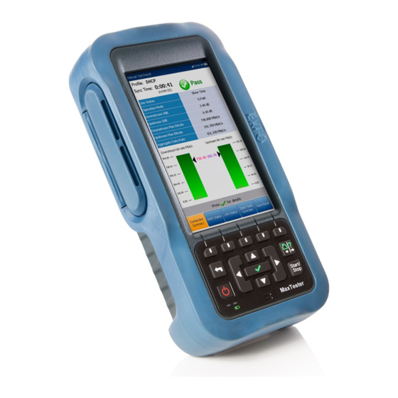
Ethernet ports of the MAX-630G allow it to be used inside the home to test all the way to the end point of the service. The MaxTester 630G test set case is an aluminum enclosure with rubber over mold, which makes it ideal for field use. Its display is a back-lit LCD featuring 480 x 800 resolution;... -
Page 8: Typical Applications
Introducing the MAX-630G Typical Applications Typical Applications ADSL2+ ATM/PTM and VDSL2 testing Optional ADSL2+ and VDSL2 bonding support Supports Ping, FTP , and Traceroute tests with optional support for Web Browser, VoIP and IPTV analysis Ethernet testing for qualifying FTTx service at the customer premises ... -
Page 9: Using The Maxtester
Introducing the MAX-630G Using the MaxTester Using the MaxTester The MaxTester is tested IEC IP54 which means that it is not affected by dust or water splashing against the enclosure from any direction. This protection is only valid when both side doors are properly closed. If the equipment is used in a manner not specified by the manufacturer, the protection provided by the equipment may be impaired. - Page 10 Introducing the MAX-630G Using the MaxTester Front Touchscreen Power LED Battery LED Speaker MAX-630G...
- Page 11 Introducing the MAX-630G Using the MaxTester Back Stylus Screws Screws Battery Door Note: The MAX-630G enclosure may become warm during normal use. G.fast/VDSL2/ADSL2+ Multi-play Test Set...
-
Page 12: Cable Connections
(pins 3-4), use the red cable (pair 2) of the provided ACC-BD-RJ test cable, RJ14 to dual RJ-11, and an RJ11 female adapter ACC-RJ11-ADPTR. Technical Specifications To obtain this product’s technical specifications, visit the EXFO Web site at www.exfo.com. MAX-630G... -
Page 13: Conventions
Introducing the MAX-630G Conventions Conventions Before using the product described in this guide, you should understand the following conventions: ARNING Indicates a potentially hazardous situation which, if not avoided, could result in death or serious injury. Do not proceed unless you understand and meet the required conditions. -
Page 15: Safety Information
ARNING Use only accessories designed for your unit and approved by EXFO. For a complete list of accessories available for your unit, refer to its technical specifications or contact EXFO. -
Page 16: Electrical Safety
When using the MaxTester while connected to the AC/DC adapter/charger, make sure you do not position the equipment so that it is difficult to disconnect the adapter/charger from the AC mains. ARNING Use only accessories that meet EXFO specifications. MAX-630G... -
Page 17: Equipment Ratings
Safety Information Equipment Ratings Equipment Ratings Equipment Ratings Temperature Operation 0 °C to 40 °C (32 °F to 104 °F) Storage –40 °C to 70 °C (–40 °F to 158 °F) Relative humidity unit ≤ 95 % non-condensing ... -
Page 19: Getting Started With The Maxtester
Getting Started with the MaxTester Turning the Unit On/Off When you turn the unit on, you may use it immediately under normal conditions. When the unit is turned off, it keeps the following parameters in its internal memory: Setup including system, application, and modem settings. ... - Page 20 Getting Started with the MaxTester Turning the Unit On/Off To enter suspend mode: Press for about 2 seconds. The MaxTester will stay in suspend mode for 2 hours, after which it will automatically shutdown. This prevents complete battery discharge and ensures maximum battery performance. Note: If you have the touchscreen option, you will not be able to wake up the MaxTester just by touching the display, after putting the unit into suspend mode.
-
Page 21: Using Menus And Keypad
You can access various tools from the keypad or menu. Menu options may differ depending on your unit configuration. Home menu is where you can access DSL/IP Tests, System Settings, or EXFO Connect. Each test has a sub menu. To navigate through the items, use the arrow keys. ... -
Page 22: Keypad
Getting Started with the MaxTester Keypad Keypad Arrow keys Function keys Home/Help Back Start/Stop test Power Enter Power button on the lower left side of the unit is used to power the unit on and off. Arrow keys navigate the screen to access and modify parameters. ... -
Page 23: Using Screenshot Capture/Online Help
Getting Started with the MaxTester Using Screenshot Capture/Online Help Using Screenshot Capture/Online Help Using the Home/Help button, you can take a screenshot of the current page display or view online help. If screenshots are Enabled, you will have to select No in the popup message before accessing the online help. (See below.) Screenshot Capture To take a screenshot:... - Page 24 Getting Started with the MaxTester Using Screenshot Capture/Online Help Online Help Online help is available at any time. Most test operations pause while you view help, but will resume automatically when you exit help. To access help about the current function at any time: Press and hold the ? key.
-
Page 25: Setting Up The Max-630G
Wi-Fi Test (GVXAA and GVXAB models only) scans and collects Wi-Fi information and is not related to Copper or DSL/IP Tests. EXFO Connect opens to EXFO Connect Client and Comms (Communications) Setup. Note: If you have the touchscreen option, any reference to pushing buttons on the keypad can be replaced in most cases by clicking/tapping the touchscreen. -
Page 26: System Settings
Software Options allows you to enable/disable purchased feature options. Information displays information About EXFO and unit details pertaining to hardware/software/product info. Upload Setup allows you to enable and select an upload method ... -
Page 27: Display And Language
Setting Up the MAX-630G Display and Language Display and Language To fit your work environment, you may adjust the LCD brightness, display the time and Active Sync, and change the display language. If your unit has a touchscreen, you can also calibrate it here. Plus, you can Enable Screenshots which uses the Home/Help button. - Page 28 To Enable Screenshots, select Enabled (default), then the Screenshot file format in either JPG (default) or GIF, and where you would like to Save Screenshot to: USB (default), EXFO Connect Client, or FTP. If USB, the image is saved to a directory called ...
- Page 29 Setting Up the MAX-630G Display and Language Remote Display The Remote Display function allows you to connect the MaxTester to your computer remotely, using PC TightVNC or RealVNC client application, and a Bluetooth or USB connection. Enable Remote Display button starts the Remote ...
- Page 30 A third, right-hand column displays a checkmark if the device is Paired. Note: Use only an EXFO certified Bluetooth dongle. To initiate remote display: 1. Connect the Bluetooth Dongle or USB Connection to a USB port on the MaxTester.
-
Page 31: Date And Time
Setting Up the MAX-630G Date and Time Date and Time When saving results, the unit also saves the corresponding Date and Time. Date allows you to enter the date according to the following formats: yyyy-mm-dd dd-mm-yyyy mm-dd-yyyy ... -
Page 32: Battery Info
Setting Up the MAX-630G Battery Info Battery Info You can set your unit to automatically switch to suspend mode independently for the battery or DC power modes. This is useful for example if you want to save battery power but do not want to be hindered by unwanted switches between modes when using DC power. - Page 33 Setting Up the MAX-630G Battery Info Modem Power OFF: Immediately for when a DSL/IP test is completed or stopped. In this mode, the modem is powered on when DSL/IP test starts. Idle values power off the modem within a defined period after an ...
-
Page 34: Software Options
Setting Up the MAX-630G Software Options Software Options To activate a newly purchased option key on your MaxTester, please see the Software Options procedures in the MaxTester CQ-DSL Release Notes that accompanied your unit. DSL Options This screen lists all the DSL Configured Options which are present on the unit. - Page 35 Setting Up the MAX-630G Software Options Platform Options This screen lists all the Platform Configured Options which are present on the unit. Possible options are: FTP Result Upload Touchscreen Support Wi-Fi Test G.fast/VDSL2/ADSL2+ Multi-play Test Set...
-
Page 36: Information
Setting Up the MAX-630G Information Information About EXFO The About tab contains contact information should you require technical assistance. MAX-630G Information The Information tab displays information about the product, software, and memory installed on the device. The page also identifies hardware information. -
Page 37: Upload Setup
Setting Up the MAX-630G Upload Setup Upload Setup Upload Enable The Upload Enable function allows you to upload your test result files. The Out-band Upload Method allows you to use one of the following methods: Wi-Fi allows you to upload files from the ... - Page 38 The DSL In-band Upload method supports DSL or Ethernet, and can be set to either Enable or Disable. Export to EXFO Connect Client allows you to Enable/Disable this location to export your CQ and DSL test reports. To select the Upload method: 1.
- Page 39 Setting Up the MAX-630G Upload Setup FTP Setup The FTP Setup function allows you to configure the file transfer information using the following: Address Format allows you to select the FTP server address type: IP Address FTP Server Address allows you to set either the ...
- Page 40 Setting Up the MAX-630G Upload Setup Wi-Fi Setup The Wi-Fi Setup pages allows you to connect your MaxTester to a Wi-Fi network. Select a Wi-Fi Network for Upload lists the available secure Wi-Fi networks in range and presently connected. (Unsecured Wi-Fi networks are not supported.) The last three networks that were connected are also listed, whether or not they are presently connected to the MaxTester.
- Page 41 Setting Up the MAX-630G Upload Setup To connect your MaxTester to a Wi-Fi network: 1. Press the down arrow key to highlight the list box and press to get into the list. 2. In the list, press the up/down arrows to select the desired network. 3.
- Page 42 Setting Up the MAX-630G Upload Setup Select Network The Select Network page allows you to search for a specific Wi-Fi network. Network Name opens the alphanumeric editor screen allowing you to enter the name of the desired Wi-Fi network. Security lists the following wireless security ...
- Page 43 Setting Up the MAX-630G Upload Setup Ethernet Setup The Ethernet Setup function allows you to configure the line and access modes, etc for an Ethernet connection, using the following parameters: Access Mode options are DHCP , Static, or PPPoE. WAN Link Speed is a choice between Auto ...
- Page 44 Setting Up the MAX-630G Upload Setup The following parameters are available only when Access Mode is Static. IP Address is the address for the unit that is actively connected to your network or the internet at the time of login. Gateway is the IP address of the default gateway.
-
Page 45: Wi-Fi Test
Setting Up the MAX-630G Wi-Fi Test Wi-Fi Test Selecting the Wi-Fi Test icon (GVXAA and GVXAB models only) activates the Wi-Fi Scan function, listing all the Wi-Fi (wireless) networks available to you. Wi-Fi Scan The Wi-Fi Scan tab displays all wireless networks available with details that allow you to compare them. - Page 46 Setting Up the MAX-630G Wi-Fi Test Details of the selected Network Name include: Signal (RSSI) strength may list one of the following levels with the table cell shown in the corresponding colour: No Signal (< -90/black) Very Low (-90 to -82/red) ...
-
Page 47: Exfo Connect
Result screen. When DSL is selected, the following message is displayed: DSL connection was chosen for EXFO Connect. Please use EXFO Connect button inside DSL Manual test Upload/Save Results page. Disable Connection option disables uploads via Wi-Fi or the Ethernet. - Page 48 Setting Up the MAX-630G Comms Setup When Wi-Fi or Ethernet are selected, their respective icons are displayed in the top right-hand corner of the navigation bar. The status of whether or not a connection is present is indicated by the colour of the icon: green, yellow, or red.
-
Page 49: Setting Up Dsl/Ip Tests
Setting Up DSL/IP Tests DSL Main Menu Page DSL Main presents the main menu page which allows you to navigate to each icon using the up/down left/right arrow keys on the keypad. Press access a test or bring up the sub-menu of the selected icon: For Auto, Manual, or Ethernet, the test will start ... -
Page 50: Test Configuration
Setting Up DSL/IP Tests Test Configuration Test Configuration The MaxTester supports 3 types of test applications: Auto Test, Manual Test, and Ethernet Test. Configuration parameters for all 3 test applications are saved into a test configuration profile. A default profile is provided with a predefined set of parameters for all test applications. - Page 51 Setting Up DSL/IP Tests Test Configuration Setup Profile Name This alphanumeric editor screen allows you to change parameter values and save changes to a new word. To use the editor screen: 1. Press the up/down left/right arrows to navigate the on-screen keyboard.
- Page 52 Setting Up DSL/IP Tests Test Configuration Connection Setup The Connection Setup tab allows you to configure the line and access modes, etc of your test dependent on your unit’s Software Options and model Information. The V2XAA unit does ADSL Annex A, VDSL2 Bonding, and Vectoring.
- Page 53 Setting Up DSL/IP Tests Test Configuration ADSL2+ (xA/P2) - if VDSL2 option disabled, ADSL Annex A mode. VDSL2-30a (Pair 1) - if VDSL2 option is enabled. VDSL2 Bonding - if VDSL2 and Bonding options are enabled. The GVXAA unit does ADSL Annex A on pair 1 and supports bonding. The Test Interface setup options for the GVXAA module are the ...
- Page 54 Setting Up DSL/IP Tests Test Configuration Annex M allows you to Enable/Disable this option when Test Interface is: VDSL2/ADSL2+ or VDSL2/ADSL2+ Bonding for V2XAA and GVXAA units. VDSL2/ADSL2+ (xA/P2) for V2XAB unit. VDSL2/ADSL2+ (xA/Pair 1) for GVXAB unit. ...
- Page 55 Setting Up DSL/IP Tests Test Configuration Sync Timeout Period enables you to enter the duration, between 2 and 30 minutes, to run a DSL test from activation to reaching Show Time. Keep Sync Time is either: Continuous where the test runs until you manually stop it, or ...
- Page 56 Setting Up DSL/IP Tests Test Configuration G.INP allows you to Enable/Disable the standards based Physical Layer Retransmission scheme for impulse noise protection. This entry applies only to Auto and Manual tests. NAT (network address translation) allows you to Enable/Disable the ...
- Page 57 Setting Up DSL/IP Tests Test Configuration The following parameters are available only when Access Mode is IPoA or Static. IP Address is the address for the unit that is actively connected to your network or the internet at the time of login. Gateway is the IP address of the default gateway.
- Page 58 Setting Up DSL/IP Tests Test Configuration 4. Press to confirm the value. 5. If you make any changes to the parameter values, press the on-screen function keys to save or cancel your input. LAN Setup The LAN Setup tab is available in Ethernet Test Setup and Manual Test Setup when the Access Mode set in Connection Setup is not Sync Only.
- Page 59 Setting Up DSL/IP Tests Test Configuration To configure LAN setup values: 1. Press the up/down arrows to select the desired parameter. 2. Press the left/right arrow keys to view and select the options. 3. Press on a value to open a list box of options or the alphanumeric editor screen and use the navigation keys to scroll through.
- Page 60 Setting Up DSL/IP Tests Test Configuration Thresholds The Thresholds tab allows you to define DSL parameter criteria. For D/S (downstream) and U/S (upstream) data rates, there are OK and Min (minimum) bit rates defined to indicate unacceptable, marginal, and acceptable rates. D/S and U/S OK bit rate: ...
- Page 61 Setting Up DSL/IP Tests Test Configuration 4. Press to confirm the value. 5. If you make any changes to the parameter values, press the on-screen function keys to save or cancel your input. Select Tests The Select Tests page allows you to Enable/Disable the following optional sub-tests, within the 3 types of test applications.
- Page 62 Setting Up DSL/IP Tests Test Configuration Throughput Test (GVXAA and GVXAB models only) implements the iPerf3 or Ookla tool for active measurements of the maximum achievable bandwidth on IP networks. Note: Ookla Privacy Policy: http://www.speedtest.net/privacy You, end user, understand and acknowledge, by performing the test contained in the Speedtest Powered Software Application, that Ookla, LLC may collect your IP address during the test and share it with selected third parties.
- Page 63 Setting Up DSL/IP Tests Test Configuration IPv6 Select Tests When IPv6 (DHCP) is set as the Access Mode, the Select Tests tab allows you to Enable/Disable only the Ping parameter. To set the parameter: 1. Press the left/right arrow keys to toggle between Enable/Disable.
-
Page 64: Test Setup
Setting Up DSL/IP Tests Test Setup Test Setup The Test Setup tab allows you to configure profile values for the optional sub-tests within the 3 types of test applications. You must highlight the sub-test on the Select Tests page in order to display the sub-test’s parameters on the Test Setup page. - Page 65 Setting Up DSL/IP Tests Test Setup Communication Channel is the parameter based on either UDP or TCP . Controller Setup button opens a new page that allows you to set the required VoIP parameters for the unit. Proxy Setup button opens a new page that allows you to set ...
- Page 66 IP network session. Address Format (read only) displays DNS Name. Domain (read only) displays the domain name www.exfo.com. To enter a user name: 1. Press to open the alphanumeric editor screen and use the navigation keys to scroll through.
- Page 67 Setting Up DSL/IP Tests Test Setup Proxy Setup Proxy is the registered /proxy sip server. The Proxy Setup Info page allows you to set the following required server’s VoIP parameters: Proxy User Name allows you to enter alphanumeric characters in this field using the editor screen to create a name.
- Page 68 Setting Up DSL/IP Tests Test Setup IPTV Test Setup IPTV test supports STB (set-top box) emulation mode over xDSL and Ethernet interfaces enabling the MaxTester to join and leave multicast IPTV streams. The following parameters can be configured from the Test Setup tab: Display Mode is either the Channel Name or # ...
- Page 69 Setting Up DSL/IP Tests Test Setup Clone Data WAN (only available in Manual Test Setup) allows you to add the WAN configuration from the Connection Setup tab to this test, by selecting Yes. If you select No, all the parameters from the Connection Setup page, beginning with Access Mode, are listed and can be modified.
- Page 70 Setting Up DSL/IP Tests Test Setup Channel List Setup The Channel List Setup page in the IPTV test setup provides a tool for you to create an alias table. It allows you to join/leave an IPTV stream using a symbolic name or TV channel number instead of the IP address.
- Page 71 Setting Up DSL/IP Tests Test Setup To setup the channel list: 1. Press the up/down, right/left keys to select the desired channel parameter. 2. Use the on-screen function buttons to create or edit the channel list. 3. Use the navigation keys to select the Previous/Next Entry button(s) and press to select the entry to be highlighted and edited.
- Page 72 Setting Up DSL/IP Tests Test Setup On-screen function buttons: Add/Insert is available only when a blank entry is highlighted. When the button is pressed, the first available channel from the alias Channel List is automatically added to this list of channels. Upon highlighting another blank entry, the next channel from the alias table is added, and so on.
- Page 73 Setting Up DSL/IP Tests Test Setup Ping Test Setup The Test Setup tab is available only if Access Mode is not Sync Only. Address Format is URL, IP Address, or Gateway. When IPv6 (DHCP) is set as the Access Mode in Connection Setup, IP Address is changed to IPv6 Address.
- Page 74 Setting Up DSL/IP Tests Test Setup Enter IPv6 Address The alphanumeric editor screen allows you to add and change parameter values, and save changes to an IPv6 Address. You must enter a value for each of the 8 IPv6 octets for example, 2001:db8:0:0:0:0:2:1. To use the editor screen: 1.
- Page 75 Setting Up DSL/IP Tests Test Setup Upload File Size (kB) is the number of bytes or size of the file to be uploaded to the server. Sim. Up Sessions (GVXAA and GVXAB models only) is the number of simultaneous sessions required to upload the file, from 1 to 4.
- Page 76 Setting Up DSL/IP Tests Test Setup HTTP Test Setup The HTTP Test Setup tab allows you to enter the destination IP address or Web site URL to be downloaded (depending on the test selected) from the HTTP server. Download Address is either the URL or IP ...
- Page 77 Setting Up DSL/IP Tests Test Setup Throughput Test Setup The Throughput Test Setup tab (GVXAA and GVXAB models only) allows you to select the Test Type, either iPerf3 Test or Speedtest by Ookla If iPerf3 Test, the following parameters can be configured: Address Format is URL or IP Address.
- Page 78 Setting Up DSL/IP Tests Test Setup If Speedtest by Ookla, you can configure the following parameters: Show Privacy Statement displays the Ookla Privacy Policy (noted below) each time you run the test, if you select Yes. Select No to forgo displaying the statement.
- Page 79 Setting Up DSL/IP Tests Test Setup Traceroute Test Setup The Traceroute Test Setup tab allows you to configure the following parameters: Address Format is URL or IP Address. Destination Address is the destination IP or URL address. Max Hops specifies the maximum number of ...
- Page 80 Setting Up DSL/IP Tests Test Setup Web Browser Test Setup The Test Setup page for the web browser content is displayed when the Web Browser Test is highlighted on the previous Select Tests tab. Here you can edit the Bookmarks and Home URL. Bookmarks lists 9 entries.
-
Page 81: Setup
Setting Up DSL/IP Tests Setup Setup The Setup function displays the following sub-menu: Modem Settings allows you to set the display and power parameters of the modem. Application Settings allows you to preset the unit with specific DSL measurement values. VoIP Phone Book includes pages to setup and ... - Page 82 Setting Up DSL/IP Tests Setup If your modem is V2XAB/GVXAB, then DSLAM entry is visible and allows you to choose the following: Annex B Annex B and UR2 To access the modem settings: 1. From , select DSL/IP Tests, Setup, and then Modem Settings. 2.
- Page 83 Report Format is MaxTester, HTML, MHTML, or XML as the generated report format. Note: If EXFO Connect Client is selected, the available selections for Report Format are only MHTML and XML. Result File Storage Location allows you to select where to save your ...
- Page 84 Setting Up DSL/IP Tests Setup CRC/ES/SES Beep allows you to Enable/Disable an error-warning beep while running a test. By selecting the error(s), you can immediately identify lines with DSL errors. They are sampled periodically and if any new errors are detected, the tester will generate a short beep.
- Page 85 Setting Up DSL/IP Tests Setup 3. Press on a value to open a list box of options or the alphanumeric editor screen and use the navigation keys to scroll through. 4. Press to confirm the value. Test List Setup The Test From List Setup and Test To List Setup pages allow you to manage the entries of the list.
- Page 86 Setting Up DSL/IP Tests Setup File Name The File Name tab sets up the standard configuration for automatically naming a result file. You can only Enable/Disable the entries. All enabled entries are considered for file name generation. File Name Preview displays a preview of the file ...
- Page 87 Setting Up DSL/IP Tests Setup Change Order Change Order page allows you to change the order of the entries in the file name. To change the order: 1. Press to get into the list. 2. Use the up/down arrow keys to select the desired entry.
- Page 88 Setting Up DSL/IP Tests Setup VoIP Phone Book The Phone Book menu presents a selection of functions which allow you to manage phone numbers relevant to performing VoIP tests. The functions are as follows: Phone Book Details displays an editable list of ...
- Page 89 Setting Up DSL/IP Tests Setup Phone Book Details The Phone Book Details page allows you to view, add, and edit VoIP Phone Book entries. Selected Entry is the current SIP Address entry that you selected. Entry displays the entry number and cannot be ...
- Page 90 Setting Up DSL/IP Tests Setup Enter SIP Address The alphanumeric editor screen allows you to add and change parameter values, and save changes to the Phone Book. To use the editor screen: 1. Press the up/down left/right arrows to navigate the on-screen keyboard.
- Page 91 Setting Up DSL/IP Tests Setup To load a phone book: 1. Select the Storage Location using the left/right arrow keys. 2. Press to display the list of options. 3. Using the up/down arrow keys, select a file name to load. 4.
- Page 92 Setting Up DSL/IP Tests Setup Delete Phone Book The Delete Phone Book page allows you to delete a phone book. The page lists phone book files stored at a particular location and displays the Loaded File name and date of the last phone book loaded. The Storage Location lists the location where the ...
-
Page 93: Running Dsl/Ip Tests And Viewing Results
Running DSL/IP Tests and Viewing Results The MaxTester is designed to make DSL/IP turn-up easy. The unit will emulate an customer CPE modem to the point that it can handshake and connect with an DSLAM and report the upstream and downstream parameters. -
Page 94: Dsl/Ip Connection Summary
Running DSL/IP Tests and Viewing Results DSL/IP Connection Summary DSL/IP Connection Summary The Connection Summary tab allows you to view the pass/fail status and details of the test results. When the Test Interface for Auto Test or Manual Test is set to ADSL2+ or VDSL2 bonding mode, there will be 2 columns of results. - Page 95 Running DSL/IP Tests and Viewing Results DSL/IP Connection Summary Downstream/Upstream Max Bitrate displays the D/S (downstream) and U/S (upstream) maximum attainable bit rates that the circuit can handle as determined by the remote terminal and CO during the training phase. Values can be greater than the actual bit rate. If the Operation Mode is bonded, the 2-DSL line Max Bitrate is combined.
-
Page 96: Ethernet Connection Summary
Running DSL/IP Tests and Viewing Results Ethernet Connection Summary Ethernet Connection Summary When set up over Ethernet, the available test results are the following: WAN/LAN Port Line Status displays Booting (GVXAA and GVXAB models only), Connected, or Disconnected for the particular line connection under test. -
Page 97: Wan Status
Running DSL/IP Tests and Viewing Results WAN Status WAN Status The WAN Status tab allows you to view the status information of the connection between the WAN port of the unit and the ISP (internet service provider). For Manual Test, you can also select which triple-play test you want to run or view. - Page 98 Running DSL/IP Tests and Viewing Results WAN Status WAN IPv6 parameter replaces the IPv4 Assigned IP , when IPv6 (DHCP) is set as the Access Mode in Connection Setup, because there are 2 assigned IPv6 addresses: the global one (WAN) and the local one (Link-Local).
-
Page 99: Lan Status
Running DSL/IP Tests and Viewing Results LAN Status Login (for Manual Test only) button allows you to start the test application, which also stops the previous test. For example, if the current test is IPTV, and you select Data Test and press the Login button, the IPTV Test stops and the unit will reconnect WAN for Data Test if the WAN setup is different between these 2 tests. -
Page 100: Voip Call
Running DSL/IP Tests and Viewing Results VoIP Call VoIP Call The VoIP Call feature allows you to place and receive VoIP calls while displaying phone numbers, call status, and statistics. Enter Address displays the dialed number entered from the editor screen or selected from the Recent Dialed Numbers list or Phone Book. - Page 101 Running DSL/IP Tests and Viewing Results VoIP Call VoIP Statistics display histograms showing the current values of each of the following: Avg. MOS - average Mean Opinion Score, which provides a relative measurement of VoIP call quality. Avg. R-Factor - average R-Factor score, which is a VoIP ...
- Page 102 Running DSL/IP Tests and Viewing Results VoIP Call Touch-Tone Keypad The Touch-Tone Keypad allows you to enter a DTMF number to dial a VoIP Call. The page contains alphanumeric keys to send a DTMF tone, and special-use alpha keys: A, B, C, D. For example, some systems require these keys for entering admin mode.
- Page 103 Running DSL/IP Tests and Viewing Results VoIP Call Function Keys: Dial/Hang Up button allows you to dial the selected or entered number, or disconnect the dialed call. Add To PhoneBook saves the entered number to the Phone Book. ...
- Page 104 Running DSL/IP Tests and Viewing Results VoIP Call Recently Dialed The Recently Dialed page contains a list of previously dialed SIP entries which you can select to make your call. To select an entry: 1. Use the up/down arrow keys to select an entry. 2.
- Page 105 Running DSL/IP Tests and Viewing Results VoIP Call Threshold Settings The Threshold Settings page allows you to set the VoIP test threshold parameters. Avg. MOS is the average Mean Opinion Score, which provides a relative measurement of VoIP call quality. Avg.
-
Page 106: Voip Summary
Running DSL/IP Tests and Viewing Results VoIP Summary VoIP Summary The VoIP Summary tab allows you to view the pass/fail status and measurement details of the different parameters. If a measured value is out the thresholds configured in the VoIP Call setup, or if the WAN connection was not completed successfully, the VoIP Summary page will display a fail status. -
Page 107: Iptv Summary
Running DSL/IP Tests and Viewing Results IPTV Summary IPTV Summary The IPTV Summary tab allows you to view the pass/fail status and test results of the IPTV stream live time analysis and statistic counters and actions (Join/Leave). Line Rate is the actual rate achieved by the ... - Page 108 Running DSL/IP Tests and Viewing Results IPTV Summary Channel Analysis The Channel Analysis function provides a separate tab for every live stream channel. Each channel displays the following information: Stream Rate Info Transport Rate (kbit/s) IP Packet Rate (kbit/s) ...
-
Page 109: Join Leave
Running DSL/IP Tests and Viewing Results Join Leave Join Leave The Join Leave tab displays a list of IPTV channels from the alias table, their activity (measured Zap time), and pass/fail status. Upon successful WAN connection, the Join/Leave Channel lists are shown. To join/leave channels: 1. -
Page 110: Dsl Parameter Details
Running DSL/IP Tests and Viewing Results DSL Parameter Details DSL Parameter Details The DSL Param Details tab displays the Downstream and Upstream parameter results configured in the DSL/IP tests. When the Test Interface for Auto Test or Manual Test is set to ADSL2+ or VDSL2 bonding mode, there will be 2 pages of results, one for each DSL line-pair. - Page 111 Running DSL/IP Tests and Viewing Results DSL Parameter Details Parameter - Downstream/Upstream Actual Data Rate displays the values at which the unit and CO are connected, as negotiated during the training phase. The values should represent what the CO was set to, unless the DSL link is being subjected to high levels of noise/crosstalk.
- Page 112 Running DSL/IP Tests and Viewing Results DSL Parameter Details Interleave Delay defines the mapping (relative spacing) between subsequent input bytes at the interleave input and their placement in the bit stream at the interleave output. INP is the level of impulse noise protection. ...
-
Page 113: Dsl Statistics
Running DSL/IP Tests and Viewing Results DSL Statistics DSL Statistics The DSL Statistics tab allows you to view transfer mode statistics and DSL counters. When the Test Interface for Auto Test or Manual Test is set to ADSL2+ or VDSL2 bonding mode, there will be 2 pages of results, one for each DSL line-pair. - Page 114 Running DSL/IP Tests and Viewing Results DSL Statistics Sync loss count is the number of times the unit lost synchronization. Vector State for single VDSL2 connection mode is Active/Not Active and for G.fast mode is always Active. When Active, the VCE (vector control entity) + DSLAM asks the CPE for noise samples.
- Page 115 Running DSL/IP Tests and Viewing Results DSL Statistics G.INP RTX_C is a counter that is increased each time a frame is detected in error and has successfully been corrected by a retransmission. The Local number is received by the CPE, the Remote value received by the DSLAM.
-
Page 116: Band Information
Running DSL/IP Tests and Viewing Results Band Information Band Information The Band Information tab allows you to view a list of individual upstream or downstream band parameter details. The test results display Bits per Tone in graphical format. For G.fast, the Frequency is shown in MHz. When the Test Interface for Auto or Manual Test is set to ADSL2+ or VDSL2 bonding mode, there will be 2 pages of results, one for each DSL line-pair. -
Page 117: Loop Diagnostics
Running DSL/IP Tests and Viewing Results Loop Diagnostics Loop Diagnostics The Loop Diagnostics tab displays the characteristics and potential problems on the line, in graphical format. Some DSLAMs provide upstream SNR and Hlog per tone info to the CPE during DSL connection phase. -
Page 118: Data Tests Summary
Running DSL/IP Tests and Viewing Results Data Tests Summary Data Tests Summary The Data Tests Summary tab displays the pass/fail status of the selected data tests enabled in the connection setup. A successful WAN connection must be established in order to view the detailed results. When IPv6 (DHCP) is set as the Access Mode in Connection Setup, only Ping Test will be displayed. - Page 119 Running DSL/IP Tests and Viewing Results Data Tests Summary Note: The following are not shown if the Access Mode in Connection Setup is set to IPv6 (DHCP). Ping IP Address is the destination IP address. Ping URL is the destination URL address. ...
- Page 120 Running DSL/IP Tests and Viewing Results Data Tests Summary HTTP Test The HTTP Test tab allows you to evaluate the speed at which a particular Web page or URL or Web object can be downloaded by the unit. The page displays the HTTP Download Status/speed and results;...
- Page 121 Running DSL/IP Tests and Viewing Results Data Tests Summary Speedtest by Ookla The Throughput Test tab (GVXAA and GVXAB models only) displays the Speedtest by Ookla Test Status and the Download/Upload speed results, along with the Ping (reaction time in ms) value to the nearest server.
- Page 122 Running DSL/IP Tests and Viewing Results Data Tests Summary Note: Ookla Privacy Policy: http://www.speedtest.net/privacy You, end user, understand and acknowledge, by performing the test contained in the Speedtest Powered Software Application, that Ookla, LLC may collect your IP address during the test and share it with selected third parties.
-
Page 123: Web Browser
It is not designed for extensive browsing or to view complex web pages. Some pages containing images or animated graphics may not display fully. EXFO suggests that you use the supplied bookmarks or similar simple web pages for testing. - Page 124 Running DSL/IP Tests and Viewing Results Web Browser To edit the web address: 1. Press to highlight the URL box. 2. Press to bring up the edit screen and modify the web address. The edited URL can be used to browse the web page temporarily but it will not be saved as the Home URL.
-
Page 125: Bookmarks
Running DSL/IP Tests and Viewing Results Bookmarks Bookmarks The Bookmarks page allows you to select from a list of URLs or save the current one. URL box shows the current URL in the web browser page. On-screen function keys: ... -
Page 127: Saving, Reading, And Managing Dsl/Ip Test Results
Saving, Reading, and Managing DSL/IP Test Results Saving Results You can save a snapshot of test results into a result file during or after performing a DSL/IP test, with the MaxTester. Each Auto Test, Manual, and Ethernet test includes an Upload/Save Result tab to do so. The tab allows you to Upload &... - Page 128 Export to EXFO Connect Client is enabled in System Settings\Upload Setup. This feature allows you to save test results and export XML test reports to be uploaded to the EXFO Connect platform using the EXFO Connect Client application. Export Report ...
- Page 129 You can generate and export HTML, MHTML, or XML reports from any saved test result. Note: If EXFO Connect Client is selected, the available selections for Report Format are only MHTML and XML. Reports include: Product/General Information including Pass/Fail status.
- Page 130 Saving, Reading, and Managing DSL/IP Test Results Saving Results 4. Press the left arrow key to erase the existing value, and then use the alphanumeric keypad to enter a value. To cancel the entry, press 5. Press to accept the value. Select Result File Select Result File page displays a list of existing file names where you can save your results.
- Page 131 Saving, Reading, and Managing DSL/IP Test Results Saving Results Uploaded status column displays a successful, failed, or no upload for each file. Upload button transfers the selected files to the designated location. Delete button removes selected XML files from the internal memory. ...
-
Page 132: Managing Results
Saving, Reading, and Managing DSL/IP Test Results Managing Results Managing Results You can view, Upload, Export, and Delete any of your saved results with the MAX-630G by highlighting the Result Manager icon from the DSL Main pane and pressing Read Results The Result page allows you to select a File Name and view the results of files previously saved. - Page 133 Report File Storage Location is dependent on whether Export to EXFO Connect Client is enabled or not, in System Settings\Upload Setup. If enabled, you can select either USB or EXFO Connect Client as your test report storage location. If disabled, USB is automatically selected. G.fast/VDSL2/ADSL2+ Multi-play Test Set...
- Page 134 Saving, Reading, and Managing DSL/IP Test Results Managing Results Report Format is HTML MHTML, or XML. Note: If EXFO Connect Client is selected, the available selections for Report Format are only MHTML and XML. Export button transfers the selected file(s) to the internal memory ...
- Page 135 Saving, Reading, and Managing DSL/IP Test Results Managing Results Delete The Delete page allows you to delete a selected File Name or All selected result files previously saved in the MT internal memory only. Storage Location is the MT internal memory. ...
-
Page 137: Maintenance
Maintenance General Maintenance The MaxTester has been designed to be a rugged and lightweight piece of test equipment. The MaxTester LCD display should only be cleaned using a soft, lint-free cloth and an anti-static cleaning solution. Ordinary detergents and other cleaning solutions may cloud or scratch the surface and should be avoided. -
Page 138: Recalibrating The Unit
EXFO unit. Under normal use, the recommended interval for your MaxTester 630G is: 2 years. For newly delivered units, EXFO has determined that the storage of this product for up to six months between calibration and shipment does not affect its performance (EXFO Policy PL-03). - Page 139 (2 years) To ensure that your unit conforms to the published specifications, calibration may be carried out at an EXFO service center or, depending on the product, at one of EXFO’s certified service centers. Calibrations at EXFO are performed using standards traceable to national metrology institutes.
-
Page 140: Battery
Maintenance Battery Battery The MaxTester is equipped with a Lithium Polymer battery. ARNING Recharge the battery using only the MaxTester and with the battery properly installed in the unit. Never open the battery back panel of the MaxTester without ... - Page 141 60 °C. Replacing the Battery ARNING Only use an EXFO battery. Batteries from other suppliers could result in serious damage to the MaxTester or personal injuries. See Contacting the Technical Support Group on page 422 for information on contacting EXFO.
-
Page 142: Recycling And Disposal (Applies To European Union Only)
Charging the MaxTester battery can take up to 5 hours. This battery was custom made for your unit; replacement batteries must be ordered from EXFO. Recycling and Disposal (Applies to European Union Only) For complete recycling/disposal information as per European Directive WEEE 2002/96/EC, visit the EXFO Web site at www.exfo.com/recycle. MAX-630G... -
Page 143: Troubleshooting
10 seconds and/or until the power LED goes off. Wait for the unit to cool down, and then reboot it. Battery is defective. Contact EXFO or replace the battery. G.fast/VDSL2/ADSL2+ Multi-play Test Set... - Page 144 Troubleshooting Solving Common Problems Problem Possible Cause Solution The unit is not responding. Shut down the unit, as above. Turn the unit on again to reset it. MAX-630G...
-
Page 145: Led Statuses
Troubleshooting LED Statuses LED Statuses The left-side power and right-side battery LEDs are used to indicate specific statuses of your unit. If you notice that one of the LEDs displays a particular status, please see the table below to determine what could be causing it. -
Page 146: Contacting The Technical Support Group
Contacting the Technical Support Group To obtain after-sales service or technical support for this product, contact EXFO at one of the following numbers. The Technical Support Group is available to take your calls from Monday to Friday, 8:00 a.m. to 7:00 p.m. -
Page 147: Transportation
Troubleshooting Transportation Transportation Maintain a temperature range within specifications when transporting the unit. Transportation damage can occur from improper handling. The following steps are recommended to minimize the possibility of damage: Pack the unit in its original packing material when shipping. ... -
Page 149: 10 Warranty
10 Warranty General Information EXFO Inc. (EXFO) warrants this equipment against defects in material and workmanship for a period of one year from the date of original shipment. EXFO also warrants that this equipment will meet applicable specifications under normal use. -
Page 150: Liability
Liability Liability EXFO shall not be liable for damages resulting from the use of the product, nor shall be responsible for any failure in the performance of other items to which the product is connected or the operation of any system of which the product may be a part. -
Page 151: Exclusions
Warranty Exclusions Exclusions EXFO reserves the right to make changes in the design or construction of any of its products at any time without incurring obligation to make any changes whatsoever on units purchased. Accessories, including but not limited to fuses, pilot lamps, batteries and universal interfaces (EUI) used with EXFO products are not covered by this warranty. -
Page 152: Service And Repairs
5. Return the equipment, prepaid, to the address given to you by support personnel. Be sure to write the RMA number on the shipping slip. EXFO will refuse and return any package that does not bear an RMA number. -
Page 153: Exfo Service Centers Worldwide
Fax: +86 (755) 2955 3101 Xintian Avenue, support.asia@exfo.com Fuhai, Bao’An District, Shenzhen, China, 518103 To view EXFO's network of partner-operated Certified Service Centers nearest you, please consult EXFO's corporate website for the complete list of service partners: http://www.exfo.com/support/services/instrument-services/ exfo-service-centers. G.fast/VDSL2/ADSL2+ Multi-play Test Set... -
Page 155: Index
Index Index AC requirements ......... 11 connection setup ........46 ADSL2+........... 2, 19 select ............. 55 after-sales service ........140 thresholds ..........54 application change order ......... 81 file name ..........80 editor screen..........45 general ..........77 identification ......... 78 equipment returns........ - Page 156 ............. 82 save ............85 safety caution ............ 7 conventions ..........7 warning ........... 7 warm shutdown .......... 14 service and repairs........146 warranty service centers ........... 147 certification.......... 145 shipping to EXFO ........146 exclusions ..........145 general..........143 MAX-630G...
- Page 157 Index liability..........144 null and void........143 web browser ......... 56, 74 Wi-Fi symbol........... 31 G.fast/VDSL2/ADSL2+ Multi-play Test Set...
- Page 158 CHINESE REGULATION ON RESTRICTION OF HAZARDOUS SUBSTANCES NAMES AND CONTENTS OF THE TOXIC OR HAZARDOUS SUBSTANCES OR ELEMENTS CONTAINED IN THIS EXFO PRODUCT EXFO Indicates that this toxic or hazardous substance contained in all of the homogeneous materials for this part is below the limit requirement in SJ/T11363-2006...
- Page 159 MARKING REQUIREMENTS Product Environmental protection use period (years) Logo This Exfo product EXFO Battery If applicable.
- Page 160 Tel.: 1 978 367-5600 · Fax: 1 978 367-5700 EXFO FINLAND Elektroniikkatie 2 FI-90590 Oulu, FINLAND Tel.: +358 (0) 403 010 300 · Fax: +358 (0) 8 564 5203 TOLL-FREE (USA and Canada) 1 800 663-3936 © 2018 EXFO Inc. All rights reserved. Printed in Canada (2018-09) ...
Need help?
Do you have a question about the MaxTester 630G and is the answer not in the manual?
Questions and answers