Table of Contents
Advertisement
Quick Links
Advertisement
Table of Contents

Subscribe to Our Youtube Channel
Summary of Contents for Electronics Line 3000 iConnect
- Page 2 Catalog Number: ZI0547G (06/10) All data is subject to change without prior notice. Hereby, Electronics Line 3000 Ltd. declares that this control system is in compliance with the essential requirements and other relevant provisions of Directive 1999/5/EC. Copyright © 2010 Electronics Line 3000 Ltd. All rights reserved...
-
Page 3: Table Of Contents
Table of Contents Introduction ..........................1 1.1. Documentation Conventions ......................1 1.2. Specifications ..........................2 1.3. System Overview ........................... 2 1.4. Hardware Layout..........................4 System Installation ........................9 2.1. Pre-Installation Planning ......................... 9 2.2. Installation Procedure ........................10 2.3. Back Tamper ..........................13 2.4. - Page 4 7.6. Repeaters............................50 7.7. Wireless Siren ..........................50 7.8. Smartkeys...........................51 Entry/Exit Timers and System Tones ..................53 8.1. Entry/Exit Delay ...........................53 8.2. Arm on Exit ..........................53 8.3. Supplementary Entry Delay......................53 8.4. Entry Deviation ..........................53 8.5. Arming Tones..........................53 8.6. Home Automation Tones........................54 8.7. System Trouble Tones ........................54 8.8.
- Page 5 13.5. Find Modules ..........................83 Appendix A: Menu Structure ........................84 Appendix B: Transmitter Installation...................... 91 iConnect PIR Sensors (EL-2745/2745PI) ..................... 91 PIR Sensors (EL-2600/EL-2600PI/EL-2645/EL-2645PI) ................. 94 Magnetic Contact (EL-2601) ........................97 Universal Transmitter (EL-2602) ....................... 98 Glassbreak Sensor (EL-2606)........................100 Smoke Detector (EL-2603) ........................
-
Page 7: Introduction
1 Introduction Introduction This manual is designed to help you install the iConnect Control System . We strongly urge you to read through this manual, in its entirety, before beginning the installation process so that you can best understand all that this security system has to offer. -
Page 8: Specifications
1.3. System Overview The iConnect Control System is a full-featured wireless control system that is expected to provide a solution to the needs of most residential installations. This system has been developed based upon a design concept geared towards easy installation and use. With this in mind, the user interface is based on a simple, menu-driven model that suits the essential requirements of both the user and installer alike. - Page 9 1 Introduction Figure 1-1 shows the components that make up the system and the system’s interaction with external communication networks for all the configurations (GPRS, GSM Ethernet, and PSTN). Figure 1-1: System Architecture iConnect Installation Manual...
-
Page 10: Hardware Layout
Flat-cable interface connector to keypad, built-in speaker, microphone and siren communication module 13. Front tamper switch Auxiliary power output (for Control Systems 14. Not in use operated by AC: 10-15Vdc, for Control 15. Interface connector to Home Automation module iConnect Installation Manual... - Page 11 The Wired Zone Module is a peripheral add-on module that provides eight hardwire zones to the Control System. iConnect Control System supports one Wired Zone Module providing 8 hardwire zones (the zone range is 1 – 8). Wired Zone Module is powered by its own separate power supply. Wired Zone Module is located in its own metal housing equipped with a tamper.
- Page 12 Figure 1-8: Home Automation Module (External PLI Module) Power-line terminal connections to Main External PLI connector Board (1 - Neutral; 2 - Live) LED indicator Fuse Flash programming connector LED Indicator Interface connector to Main Board Flash programming connector Interface connector to Main Board iConnect Installation Manual...
- Page 13 The Ethernet module enables the Control System to communicate to the WEB via Ethernet, perform remote firmware update, and implement PSTN backup communication with event reporting and Two-Way Audio (TWA) control. Ethernet Communication Module is also available without PSTN (see Figure 1-13). iConnect Installation Manual...
- Page 14 Figure 1-14: PSTN Communication Module Flat cable interface connector to Main Board Metal cover USB connector to PC firmware management Telephone Line terminal block: incoming line from telephone company Telephone Line terminal block: outgoing line to telephone Metal Cover Status LED iConnect Installation Manual...
-
Page 15: System Installation
Metal based construction materials, such as steel reinforced concrete walls, reduce the range of radio transmissions. Figure 2-2: Considering Construction Materials The reduction of the RF signals’ strength is directly proportional to the thickness of the obstacle, assuming that the obstacles are of identical material. iConnect Installation Manual... -
Page 16: Installation Procedure
Step 3 – Registering Transmitters For the Control System to recognize a device, its transmitter must be registered. In general terms, transmitter registration means sending two transmissions from a device when the Control System is in Registration mode. iConnect Installation Manual... - Page 17 Control System’s ID & Password (provided by the ELAS administrator). The following procedures explain how to program the Control System’s ID (CPID) and Password. For further information regarding other Internet options and settings, see p. 77, 11 Internet Options. iConnect Installation Manual...
- Page 18 Ethernet cable, and telephone line) and make any necessary wiring connections: Connect the power cable to the AC power input on the Main board – see p. 4, 1.4.1 The Main Board. Caution: High voltage! Be careful not to touch the power cable since connected! iConnect Installation Manual...
-
Page 19: Back Tamper
To meet the requirements of EN-50131 standard, the back tamper is mandatory. 2.4. Installing Hardwire LCD Keypads The system supports hardwire LCD keypads that may be installed up to 300m (1,000 ft) from the Control System. iConnect Installation Manual... -
Page 20: Internet Communication Setup (Not Relevant To Pstn-Only Configuration)
During this sequence, the GPRS or Ethernet module receives the parameters programmed in the Control System's Internet Options – p. 77, 11 Internet Options. After the startup sequence is complete, the GPRS or LAN attempts to connect to the ELAS GPRS/LAN Proxy. iConnect Installation Manual... - Page 21 Caution: When using a SIM card with a PIN code, the installer has to make sure that the PIN code programmed in the Control System is the same as the SIM card's PIN code – see p. 72 10.7.2 PIN Code. iConnect Installation Manual...
-
Page 22: Basic System Operation
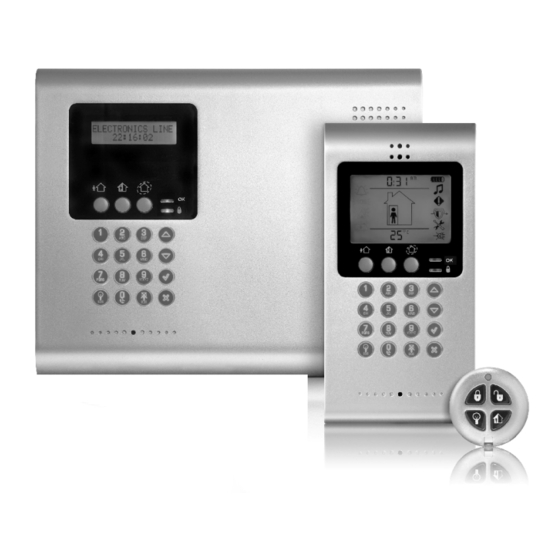
Basic System Operation iConnect Control System is available in two front panel configurations: LED and LCD. Below you will find description of the LCD front panel layout. For LED Top Cover layout see p. 19, 3.5 Front Panel Layout (LED Top Cover). -
Page 23: Front Panel Keypad And Hardwire Lcd Keypad
During standby, used to scroll through the list of system trouble conditions. Table 3-3: Front Panel Keypad and Hardwire LCD Keypad Functions Hardwire Keypad LEDs functionality is identical to those of the Front Panel keypad – see p. 16, 3.2 Front Panel System Status LEDs (LCD Top Cover). iConnect Installation Manual... -
Page 24: Lcd Display
The system is in the process of arming (displayed during exit delay). PERIMETER ARMING PART ARMING INST The system is in the process of arming with the Instant arm feature activated. PERIM ARMING INST Table 3-4: Armed Status – Unpartitioned Systems iConnect Installation Manual... -
Page 25: Front Panel Layout (Led Top Cover)
The three-button keypad allows you to make a service call, record and play an audio message, and to activate an SOS panic alarm. Arming Status LEDs System Status LEDs Service Call Button Message Record Button Message Play Button Figure 3-4: LED Top Cover iConnect Installation Manual... -
Page 26: System Status Leds (Led Top Cover)
The LED Top Cover keypad is used to activate the three basic end user functions listed in the following table. If your Control system is configured with an LED Top Cover, use a hardwire LCD keypad to perform any function that requires keypad/ LCD interface. iConnect Installation Manual... -
Page 27: Audible Notification
3.9.1. System Trouble Tones In the event of system trouble, the iConnect Control System sounds a series of tones to alert the user. To silence these tones, press and scroll through the system trouble list displayed on the LCD. When the trouble condition is restored, it is removed from the system trouble list. -
Page 28: Arming And Disarming - Unpartitioned Systems
3.9.2. Vocal Message Annunciation Certain versions of the iConnect Control System hardware support vocal annunciation of system status. If this feature is enabled in programming (see p. 61, 9.13 Vocal Messages), the system plays short messages to indicate arming, disarming, bypassed zones, system trouble, message waiting, and water alarm. - Page 29 Note: You can activate the second arming mode only during the exit delay of the first arming mode. When the first exit delay expires, you cannot activate a second arming mode. iConnect Installation Manual...
-
Page 30: Arming/Disarming - Partitioned Systems
In our example a common zone is placed in the corridor that belongs to both partitions. Only when both users leave and arm their partitions, the common zone is activated and the corridor is protected. When any of the users returns and iConnect Installation Manual... - Page 31 Enter a valid user code. If both partitions are armed, and your user code is assigned to both partitions, the system prompts Select Partition. In this case, press one of the arming keys on the front panel keypad iConnect Installation Manual...
-
Page 32: Additional Arming Options
The following example shows an Arm Status Reply message reporting that the system was fully armed by Master User. U L L A R M E D - M A S T E R iConnect Installation Manual... - Page 33 Press and hold down buttons 1 and 3 simultaneously. Figure 3-14: Fire Alarm Activation To activate a Medical alarm from the front panel keypad or hardwire LCD keypad: Press and hold down buttons 4 and 6 simultaneously. Figure 3-15: Medical Alarm Activation iConnect Installation Manual...
-
Page 34: Advanced System Operation
…within 5 minutes since an alarm, a Cancel Report event and the user number are sent to the Central Station; …at the moment when the event is being reported (communication in progress), the event reporting is not cancelled; Note: Non-alarm events (system trouble, arm/disarm etc.) are not aborted by Cancel Report. iConnect Installation Manual... -
Page 35: Zone Bypassing/Unbypassing
A Limited code enables the user to issue a code that is valid for one day only. This code automatically expires 24 hours after it has been programmed. These codes are "controlled" in that their use for Arm/Disarm is notified to the central station. Only if arm/disarm reporting is enabled during System Programming iConnect Installation Manual... - Page 36 Each user code can be assigned a 16-character descriptor. These descriptors help to identify users in the event log and in SMS Follow-Me messages. To edit a code descriptor: From the main menu, select User Codes [4]. Select a code. From the code’s sub-menu, select Descriptor [#2]. iConnect Installation Manual...
-
Page 37: Follow-Me
Select the interface type (GSM or PSTN). 4.7. Event Log The event log records the last 1022 events the system has undergone. The log uses the FIFO (First In, First Out) method, automatically erasing the oldest event when the log is full. iConnect Installation Manual... -
Page 38: Service Menu
Press ; the log is cleared -- See p.130, Appendix E: Event Table. Note: For certain versions of the iConnect Control System software, the Clear Log function may be disabled. 4.8. Service Menu The Service menu is accessible using either the Installer or Master code. This menu includes various functions that enable you to test the system effectively. - Page 39 Message Center The iConnect Control System Message Center is designed to allow the user to record a short message that may be played back later by another user. After a message is recorded, Message Waiting is displayed on the LCD until the message is played back.
- Page 40 Description… The transmitter is functioning correctly Tamper condition Battery low The transmitter is out of synchronization The transmitter is inactive – see p. 44, 7.2.3 Supervision Time Table 4-2: Transmitter Status Abbreviations Figure 4-3: TX List Display iConnect Installation Manual...
- Page 41 1 to 9 – similar to the level of detector transmitter's signal strength. It is recommended that the gap between the RF noise level and the TX signal strength be at least 2. For example, if the RF iConnect Installation Manual...
- Page 42 When using Ethernet connection, you can view the LAN IP address of the Control System. To display the IP Address: From the Service menu, select IP Display [714]; the LAN IP address of the Control System is displayed. iConnect Installation Manual...
-
Page 43: Telecontrol And Two-Way Audio
It is therefore important that the Control System distinguish between calls so that it knows when to pick up the relevant call. For this purpose the iConnect Control System employs a double call method. - Page 44 If the TWA mode is defined as "Simplex" (see p. 72, 10.6.13 TWA Mode), the audio channel opens in Listen mode (microphone active/speaker mute). To switch to Speak mode, press "1" on your telephone. To switch back to Listen mode, press "0" on your telephone. iConnect Installation Manual...
-
Page 45: Outgoing Calls
To disconnect before the end of the timeout, press " " then "#" on your telephone. 5.2. Outgoing Calls The iConnect Control System can make Two-Way Audio calls to the user or central station in the event of an alarm. This feature is designed for medical, panic alarms, and for alarm verification. 5.2.1. - Page 46 (microphone active/speaker mute). The operator may switch to Speak mode, by pressing "1" on their telephone. Pressing "0" switches back to Listen mode. For further information on how to program this feature, see p. 31, 4.6 Speed Dial Numbers. iConnect Installation Manual...
-
Page 47: Home Automation And Pgm Control
SMS Command Descriptor (up to 43 characters of Command (0=Off, 1=On) free text) # (delimiter – separates the descriptor from the Device Number (HA Units: 01-16, or 30 for PGM output) actual command) User Code (4 digits) iConnect Installation Manual... -
Page 48: Scheduling (Not Relevant To
Select an HA unit. From the HA unit’s sub-menu, select Schedule [#3]. Use keys 1 to 7 to toggle the days on and off. Value Value Sunday Thursday Monday Friday Tuesday Saturday Wednesday Table 6-1: Weekly Schedule iConnect Installation Manual... -
Page 49: Devices
From the Programming menu, select Devices, [91]. Select the type of wireless device you want to delete. Select the specific device you want to delete. From the device’s sub-menu, select Delete. Press to confirm; the device is deleted. iConnect Installation Manual... -
Page 50: Zones
7.2.3. Supervision Time The sensors in Electronics Line 3000’s supervised wireless range send a supervision signal approximately 20 minutes after its last transmission. If the system does not receive supervision signals from a specific transmitter, the transmitter is regarded as inactive. - Page 51 In unpartitioned systems, each zone can be assigned to Full Arming and/or to Part and/or Perimeter Arming in any combination. In partitioned systems, there are two types of zone arm set: Regular zones: zones assigned to full arming and/or to only one of the two partitions (Full Only or Full + P1 or Full +P2). iConnect Installation Manual...
- Page 52 To program the Chime option: From the Programming menu, select Devices, Zones [911]. Select the zone you want to program. From the zone’s sub-menu, select Chime [#06]; the zone’s current Chime setting is displayed. Select either Enabled or Disabled. iConnect Installation Manual...
- Page 53 This option enables you to determine the zone’s loop type – see p. 6, Loop Types. Note: The only Loop Type available for Zone 33 is NC. To program the Loop Type option: From the Programming menu, select Devices, Zones [911]. iConnect Installation Manual...
-
Page 54: Keyfobs
7.4. Keyfobs The iConnect Control System supports two types of keyfob transmitter, EL-2611 and EL-2714. You can register up to 19 keyfobs to the system. Figure 7-3 illustrates these transmitters and the functions assigned to their buttons. For information on registration and deletion, see p. 43, 7.2. Wireless Devices. For descriptor editing, see p. 43, 7.1 Device Descriptors. -
Page 55: Keypads
43, 7.1 Device Descriptors, and p. 43, 7.2.2 Deleting Wireless Devices. See p. 109, Wireless Terminal (EL-2724), and p. 111, Wireless Keypad (EL-2640) for registration and battery replacement procedure. The EL-2724 LEDs functionality is described in Table 7-4. Note: Wireless Terminal EL-2724 does not support partitioning. iConnect Installation Manual... -
Page 56: Repeaters
Set the wireless siren’s receiver to Registration mode – refer to the siren’s installation instructions for further information. Activate the siren using the WL Siren Test feature – see p.34, 4.8.3 Wireless Siren Test. Activate the siren again; the on-board transmitter is registered to the siren’s receiver. iConnect Installation Manual... -
Page 57: Smartkeys
Smartkeys enable the user to arm and disarm the system without needing to enter a code. You can register up to 16 smartkeys to the system. For information on registration and deletion, see p. 43, 7.2. Wireless Devices. For descriptor editing, see p. 43, 7.1 Device Descriptors. Note: Smartkey function existence is model dependant. iConnect Installation Manual... - Page 58 The Smartkey is assigned to partition 2. Table 7-5: Smartkey Partition Set Use the keys 1, 2 and 3 to toggle the current setting. Note: If you assign the Smartkey to both partitions, assign it to the full arming also. iConnect Installation Manual...
-
Page 59: Entry/Exit Timers And System Tones
Arming tones are the tones sounded by the Control System’s built-in siren and/or the wireless siren when arming and disarming the system. Each set of tones can be enabled or disabled according to the requirements of the installation. iConnect Installation Manual... -
Page 60: Home Automation Tones
21, 3.9.1 System Trouble Tones. 8.7.1. Trouble Tones The Trouble Tones option allows you to enable or disable audible trouble annunciation. To program the Trouble Tones option: From the Programming menu, select Tones, Trouble Tones [936]. Select Enabled or Disabled. iConnect Installation Manual... -
Page 61: Tones Options
To program the Speaker Volume option: From the Programming menu, select Tones, Tones Options, Speaker Vol. [9392]. Select High or Low. Note: It is not necessary to program the Speaker Volume option if "Siren" is selected for the Tones Output option. iConnect Installation Manual... -
Page 62: System Options
Medical, Panic, Fire, Gas, Flood, and Environmental zones are not included in this supervision and do not affect the system’s ability to arm. iConnect Installation Manual... -
Page 63: Panic Alarm
The AC Loss Delay is the amount of time that has to elapse before an AC Loss report is sent to the central station. If AC power is restored before the event message is sent, the event message is canceled and will not be sent. You can program iConnect Installation Manual... -
Page 64: Display Options
This option enables you to select whether the system trouble display will indicate transmitter supervision loss to the user. To program the Supervision Loss Indication setting: From the Programming menu, select System Options, Display, SV Loss Ind. [94064]. Select Enabled or Disabled. iConnect Installation Manual... -
Page 65: Pgm Output Options
Select Steady or Pulsed. Note: The Zone Status, Siren and WL Siren trigger options have a fixed Output Type; there is no need to program an Output Type for these options. Zone Status functions only when the system is disarmed. iConnect Installation Manual... -
Page 66: Guard Code
Guard Code Report Guard Code Report option allows reporting of the Arm/Disarm events (including Disarm after an Alarm) to the Central Station even if the Arm/Disarm event group reporting is disabled – see p. 75, 10.9.1 Event Reporting. iConnect Installation Manual... -
Page 67: No Arm" Indication
Press 9.12. Microphone/Speaker Options In addition to the built-in microphone and speaker, the iConnect Control System Control System supports an external microphone/speaker unit called Interphone. The Microphone/Speaker option allows you to choose which microphone and speaker are in use. You can choose one mic./speaker (internal or external) to function exclusively or both may function simultaneously. -
Page 68: Installer Access
9.15. Auto Log View (for future use) Auto Log View is a future option that is not available in the current firmware. The default setting for this option is disabled. Electronics Line 3000 recommend that you do not change this setting. 9.16. Daylight Savings Using the Daylight Savings option, the system is able to automatically adjust its clock twice a year according to the national adjustment to Daylight Saving Time. -
Page 69: Entry/Exit Trouble
Exit Delay – see p. 53, 8.1 Entry/Exit Delay. If disabled, the ARM commands will be executed with the programmed Exit Delay. From the Programming menu, select System Options, WEB Immed. Arm [9420]. Select Enabled or Disabled. iConnect Installation Manual... -
Page 70: Battery Type
From the Programming menu, select System Options, T014A, Enable T014A [94241]. Select Enable or Disable. To reset messages: From the Programming menu, select System Options, T014A, Message Reset [94242]. The system Prompts: "Messages Reset OK?" Press " " to reset the messages. iConnect Installation Manual... -
Page 71: Communications
The Two-Way audio option determines whether Two-Way Audio is enabled for the account. For further information, see p. 39, 5.2.2 TWA Alarm Reporting. To program the Two-Way Audio option for an account: From the Programming menu, select Communications, Accounts [951]. iConnect Installation Manual... -
Page 72: Report Cycles
Enter a value between 01 and 15. Press In the example illustrated in Figure 10-1, Account 1 is programmed with 2 call attempts, Account 2 is programmed with 3 call attempts and the number of report cycles programmed is 3. iConnect Installation Manual... -
Page 73: Vocal Message Dialer
Enter up to 16 digits. Use the key to enter "*", "#", "," (pause), "T" (switch to DTMF tone dialing), "P" (switch to pulse dialing) or "+" (international code). Use the key to delete one character at a time. Press when you have finished editing. iConnect Installation Manual... -
Page 74: Remote Programming
PC either on-site or from a remote location. The software provides a comprehensive interface to the iConnect Control System designed to facilitate programming. There are 3 access levels available: Supervisor (full access), Technician (limited access to the program, a technician is not able to view or change user codes or the RP access code), and Operator (access to user operations, such as arming and disarming the system). - Page 75 Enter six digits, then press RP Communication Interface For remote programming, the iConnect Control System can employ GPRS, GSM, Ethernet, or PSTN communication. To program the RP communication interface: From the Programming menu, select Communications, Remote Prog., RP Interface [9523].
-
Page 76: Service Call
10.4.2. WEB Remote Programmer (Relevant only when using ELAS connection) Electronics Line 3000's WEB-based Remote Programmer (WEB RP) allows the installer or service provider to operate and program the system via the WEB using ELAS database to get the list of supported Control Systems. To access WEB RP, the installer must enter user name and password. - Page 77 Select your country from the options available. Note: Electronics Line 3000 offers custom telephone line parameter settings for countries that do not appear in the list of pre-defined options. If your country does not appear among the available options, select the option Custom Settings.
-
Page 78: Gsm Options (Not Relevant To Pstn Only Or Ethernet Configuration)
When using a SIM card with an activated PIN code, the installer has to make sure that the PIN code programmed in the Control System is the same as the SIM card's PIN code. The PIN code should be programmed in the system before inserting the SIM card in the GSM module. iConnect Installation Manual... - Page 79 GSM Media Restore is registered in the log and sent to central station. To disable the GSM Media Loss feature (cancel the GSM Media Loss events) enter 000. To program the GSM Media Loss Time: From the Programming menu, select Communications, Comm. Options, GSM Options, GSM ML Time. [954146]. iConnect Installation Manual...
-
Page 80: Twa Event Report Options
Press when you have finished editing. 10.8.4. Remote Firmware Update Electronics Line 3000’s Remote Firmware Update feature allows the Installer or service provider to perform firmware update from a remote PC using WEB communication. Note: Before performing the firmware update, locally disarm the system and make sure that there are no AC LOSS or BATTERY LOW conditions. -
Page 81: Event Options For Central Station Reporting
Events reported using the Vocal Message Dialer are divided into event groups that correspond with the pre-recorded event messages. This allows you to enable or disable the Vocal Message feature for a specific group of events. For further information on this feature, see p. 67, 10.3 Vocal Message Dialer. iConnect Installation Manual... - Page 82 Disarm/Partition 1 Disarm/Partition 2 Disarm Disarm after Alarm Water [#8] Zone Water Alarm (Flood) To enable/disable the vocal message for an event group: From the Programming menu, select Communications, VM Event Opt. [956]. Select an event group. Select Enabled or Disabled. iConnect Installation Manual...
-
Page 83: Internet Options (Relevant To Ethernet/Gprs & Elas Configuration)
From the Programming menu, select Communications, Internet, GPRS Options, APN [95761]. Enter the APN name provided by the cellular provider. Use the "1" key to enter ".", key to insert and the key to delete one character at a time. iConnect Installation Manual... -
Page 84: Lan Network Parameters
From the Programming menu, select Communications, Internet, LAN Options, Gateway [95773]. Enter the Gateway’s IP address. Press the key as many times as necessary to select "." and the key to delete one character at a time. iConnect Installation Manual... - Page 85 The testing and status options of the Internet connection status should provide the installer with the exact source of the problem when the Control System is not capable of reporting via LAN. See p. 130, Appendix E: Event Table. iConnect Installation Manual...
-
Page 86: Home Automation Programming
Control System’s plastic housing. Note: The iConnect System's home automation features require the use of an external power-line interface when used in an 110V/60HZ power system. 12.1. X10 Overview The Control System’s home automation feature employs the X10 protocol and this enables compatibility with a wide... - Page 87 To program an HA unit to be included in the Randomize feature: From the Programming menu, select HA Programming, HA Units [961]. Select an HA unit (01-16). From the HA unit’s sub-menu, select Randomize [#09]. Select Enabled or Disabled. iConnect Installation Manual...
-
Page 88: House Code
PGM output is not affected by HA Control parameter. Remote activation of PGM is possible, even when HA control is disabled, as long as the PGM output trigger is defined as Telecontrol – see p. 59 9.7.1 Output Trigger. iConnect Installation Manual... -
Page 89: System Initialization
Note: If a connected module is not included in the list, check the wiring connections and run this test again. iConnect Installation Manual... -
Page 90: Appendix A: Menu Structure
Appendix A: Menu Structure Appendix A: Menu Structure Legend: Installer code required Master code required iConnect Installation Manual... - Page 91 Appendix A: Menu Structure iConnect Installation Manual...
- Page 92 Appendix A: Menu Structure iConnect Installation Manual...
- Page 93 Appendix A: Menu Structure iConnect Installation Manual...
- Page 94 Appendix A: Menu Structure iConnect Installation Manual...
- Page 95 Appendix A: Menu Structure iConnect Installation Manual...
- Page 96 Appendix A: Menu Structure iConnect Installation Manual...
-
Page 97: Appendix B: Transmitter Installation
Appendix B: Transmitter Installation iConnect PIR Sensors (EL-2745/2745PI) The EL-2745/EL-2745PI are wireless PIR sensors designed for use with Electronics Line 3000’s supervised wireless range of receivers. The EL-2745PI sensor is designed for pet installations and provides good immunity to nuisance alarms caused by pets weighing up to 45kg (100lbs). - Page 98 The pulse counter determines the amount of beams that need to be crossed before the sensor will produce an alarm. The available options are 1, 2, 3 or Adaptive pulse count. Using the Adaptive pulse count feature, the detector chooses iConnect Installation Manual...
- Page 99 In case of a low battery (2.5 V and below), the sensor low battery condition is reported to the Control System and low battery message is displayed. When the rear tamper switch is released, the sensor sends a tamper condition to the Control System that generates tamper alarm. iConnect Installation Manual...
-
Page 100: Pir Sensors (El-2600/El-2600Pi/El-2645/El-2645Pi)
EL-2745 complies with EN-50131 2-2 Grade 2 Class II Power Supply Type C PIR Sensors (EL-2600/EL-2600PI/EL-2645/EL-2645PI) The EL-2600, EL-2600PI, EL-2645 and EL-2645PI are intelligent wireless PIR sensors for use with the iConnect Control System. All of these sensors implement a feature to combat the problem of multiple transmissions, which drastically reduce the life of the batteries. - Page 101 Mount the PCB at the required vertical adjustment and replace the PCB screw. Write the number of the zone on the sticker provided. Affix the sticker inside the front cover for future reference and replace the front cover. iConnect Installation Manual...
- Page 102 Radio or Walk Test Mode. As a precaution, these modes are limited to three minutes. After three minutes have expired, the detector switches back to normal operation. If this happens, you can reset a mode by removing and replacing the mode jumper. iConnect Installation Manual...
-
Page 103: Magnetic Contact (El-2601)
Holder Tamper Switch Loop 1cm max. Terminals Operation Mode Jumper Release Location of wiring knockout Figure B- 7: EL-2601 (Cover Off) Rear tamper mounting hole Figure B- 8: Mounting Screw Position Figure B- 9: Rear Tamper Release iConnect Installation Manual... -
Page 104: Universal Transmitter (El-2602)
Universal Transmitter (EL-2602) The EL-2602 is a universal transmitter that includes a single output for use in a wide range of wireless applications. When batteries need replacing, the EL-2602 sends a low battery indication to the Control System. iConnect Installation Manual... - Page 105 Connect the terminal block as follows: 1 - Alarm; 2 - GND. Test the transmitter, making certain that the LED is lit during transmissions. Close the front cover of the EL-2602. EL-2602 complies with EN-50131 2-6 Grade 2 Class II Power Supply Type C. iConnect Installation Manual...
-
Page 106: Glassbreak Sensor (El-2606)
Do not define the zone as 24Hr. It is recommended to register the EL-2606 to a perimeter arming group that arms the perimeter doors and windows of the premises. Avoid humid rooms – the EL-2606 is not hermetically sealed. Excess moisture can eventually cause a short circuit and a false alarm. iConnect Installation Manual... - Page 107 This means that the EL-2606 is only listening for mid- range frequencies reproduced by the glassbreak tester. It’s these mid-range frequencies that determine the sensor’s range. Note: In Normal mode, the tester will not activate the sensor unless held directly over the sensor. iConnect Installation Manual...
- Page 108 The Hand Clap test enables you to test the EL-2606 while in Normal mode. This test checks the sensors power supply, microphone and circuit board. To perform a Hand Clap test: Clap your hands loudly under the sensor; the LED flashes twice but an alarm is not generated. iConnect Installation Manual...
-
Page 109: Smoke Detector (El-2603)
Replace the cover onto its hinges and close the cover until it snaps together with the base. Smoke Detector (EL-2630EN) The EL-2603EN is a brand-name smoke alarm and transmitter designed for use with Electronics Line 3000’s supervised wireless range of receivers. - Page 110 (apart from the locations to avoid, mentioned below). The living room is the most likely place for a fire to start at night, followed by the kitchen and then the dining room. You should also consider putting smoke alarms in any iConnect Installation Manual...
- Page 111 Next to or directly above heaters or air-conditioning vents, windows, wall vents etc. that can change the direction of airflow. In very high or awkward areas where it may be difficult to reach the alarm for testing or battery replacement. iConnect Installation Manual...
- Page 112 Press and hold the Test button until the alarm sounds – see Figure B- 20. The alarm will stop sounding shortly after the button is released. iConnect Installation Manual...
- Page 113 If this happens the alarm must be replaced. Contamination is beyond our control, it is totally unpredictable and is considered normal wear and tear. For this reason, contamination is not covered by the guarantee. iConnect Installation Manual...
- Page 114 (for example petrol, paint, spirits etc), overloaded electrical circuits, arson, children playing with matches. Smoke Alarms do not last indefinitely. The manufacturer recommends replacement after 10 years as a precaution. iConnect Installation Manual...
-
Page 115: Keyfobs (El-2611/El-2714)
You can arm and disarm the system using the Smartkey. The following procedure explains the installation of the EL-2724 and its two-way registration to the receiver. For further information regarding the EL-2424 maintenance and specifications, refer to the installation instructions provided with this product. iConnect Installation Manual... - Page 116 Registration of the Control System to the EL-2724 allows the EL-2724 to recognize transmissions from the Control System. There is a five-minute time limit for the Control System registration to the EL-2724. The time starts to count down when you power up the system. iConnect Installation Manual...
-
Page 117: Wireless Keypad (El-2640)
Figure B- 28: EL-2640 (Battery Cover Off) Note: Do not write user codes on the reference card. Registration Procedure To register wireless keypads: From the Programming menu, select Devices, Keypads [914]. Select the keypad you want to register; the system initiates Registration mode. iConnect Installation Manual... -
Page 118: Flood Sensor (El-2661)
From the Programming menu, select Devices, Zones [911]. Select the zone to which you want to register the transmitter; the system initiates Registration mode. When Save? appears on iConnect LCD display, press . After registration, press the EL-2661’s tamper switch to terminate Test mode. -
Page 119: Repeater (El-2635)
Up to four repeaters can be registered to the Control System with 32 transmitters registered to each repeater. The repeater is powered by either 9VACwith a 6V rechargeable backup battery pack or 12VDC. Registration and maintenance tests are performed using a plug-in LCD programming keypad that provides a comprehensive interface to the repeater. iConnect Installation Manual... - Page 120 Figure B–30: Typical Single Repeater Application Installation Procedure Register all wireless devices to the iConnect Control System – see p. 43, 7.2.1 Registering Wireless Devices. Define the Repeater option for each zone that is intended to transmit via the repeater as "Use Repeater"...
- Page 121 The EL-2635 repeater automatically allocates a transmitter number to each newly registered device. Write this number and the zone number on the sticker provided with the sensor and stick it inside the transmitter's cover for future reference. iConnect Installation Manual...
- Page 122 TX Test is a utility that enables you to identify transmitters that are registered to the repeater and to test their signal strength. To perform the TX test: Press until 2. TX Test appears on the display. Press Activate a transmitter; the transmitter number, type and signal strength are displayed. Press to exit TX Test mode. iConnect Installation Manual...
-
Page 123: Transmitter Specifications
EL- 2661 Flood Sensor RFI Immunity: 30V/m Antenna: Built-in Internal Whip Operating Temperature: -10 to 60°C Frequency: 868.35, 433.92 or 418MHz FM Fire Protection: ABS Plastic Housing Power: 3.6V ½ AA Lithium Battery BT5055 Dimensions: 110 x 62 x 50mm iConnect Installation Manual... - Page 124 Due to the occurrence of voltage delay in lithium batteries that have been in storage, the batteries may initially appear to be dead. In this case, leave the unit in Test mode or Radio mode for a few minutes until the battery voltage level is stabilized. iConnect Installation Manual...
-
Page 125: Appendix C: Web User Application
Your new password should be no less than six characters and must start with a letter – see p. 122, Change Password. The Main Page After logging in, your system’s home page (Main Page) is displayed. Menu Bar Workspace Status Bar Figure C- 2: The Main Page iConnect Installation Manual... - Page 126 For example, if you choose Automation from the Main Menu, a list of automated appliances is displayed in the workspace. Note: SMS alerts relate only to SMS sent from ELAS (WEB User Application). iConnect Installation Manual...
-
Page 127: Options Available From Main Page
In this area you can add, delete, or change users and the User Codes for your system (for example, add codes for family members). On The Main Page menu, click Settings. Figure C- 5: Settings Button Click System Users and Codes, the following page appears: iConnect Installation Manual... - Page 128 On The Main Page menu, click Settings, then Web Interface Users and Codes, the following page appears: Figure C- 7: Web Interface Users and Codes Page Change Password Click Settings then Change Password to change the password you use to login to the Web Application. Figure C- 8: Change Password Page iConnect Installation Manual...
- Page 129 This area allows you to program where to send the alerts on home events (arming, disarming, alarm etc.) The events can be reported via email or your cellular phone. On The Main Page menu, click the Alerts area. iConnect Installation Manual...
- Page 130 In the Cellular Phone # field, enter the cellular phone number for SMS alerts. To start receiving the events messages, in the area below, select the checkboxes according to the event type and message type you prefer (email or SMS). iConnect Installation Manual...
- Page 131 Discuss this capability with your security service provider to determine if it is applicable to your system – see p. 41 Home Automation and PGM Control. On The Main Page menu, click Automation, the following page appears: Figure C- 15: Automation Page You can program turning the HA units on/off at specific hour/day of the week. iConnect Installation Manual...
- Page 132 Using IP video cameras installed in your home, the Web Application enables you to view streaming video over the Web in order to check your home and family while you are away. Discuss this capability with your security service provider to determine if it is applicable to your system. iConnect Installation Manual...
-
Page 133: Appendix D: Installing Ip Cameras (Relevant To Gprs/Ethernet & Elas Configuration)
Connect the camera to the power supply via the camera’s power jack; the camera waits to automatically receive an internal IP address. When the camera receives an IP address, the camera indicates that it has connected (for example, a green flashing LED – refer to the camera manufacturer’s installation instructions for further details). iConnect Installation Manual... - Page 134 Enter. On the camera’s security settings page, program a user name and password. When the user wants to access the camera from the iConnect Control System Web Application, they need to enter their user name and password for authentication purposes.
- Page 135 Enter the IP address that was automatically allocated to the IP camera – see step 4 of this procedure. For further information on how to install an IP camera and configure the router, refer to the manufacturer’s instructions that are supplied with both products. iConnect Installation Manual...
-
Page 136: Appendix E: Event Table
1400 User Number, Area Number = Events that are displayed in the event log only when viewed by the installer. Area number is 03 for Full, 01 For Part/ Partition 1, and 02 for Perimeter/ Partition 2. iConnect Installation Manual... - Page 137 Device Number Zone Trouble Restore 3380 Device Number RF Jamming FM Jamming 1344 Device Number FM Jamming Restore 3344 Device Number Medical Medical Alarm 1100 Device Number Medical Alarm Restore 3100 Device Number No Motion 1102 Device Number iConnect Installation Manual...
- Page 138 Smartkeys 77-80 Repeaters 81-84 Wireless Keypads 81-84 Wireless Keypads Front Panel Keypad Front Panel Keypad 92-98 Hardwire Keypads 92-98 Hardwire Keypads Wireless Siren Communication Module PSTN Communication Interface Cellular Communication Interface Ethernet Communication Interface GPRS Communication Interface iConnect Installation Manual...
-
Page 139: Appendix F: Zone Types
24Hr zones are always active. When triggered, 24Hr zones generate a Burglary alarm. These zones are used for applications that require constant protection. Event Group: Burglary 24Hr-X The 24Hr-X zone is a future option that is not available in the current firmware. Event Group: Not applicable iConnect Installation Manual... - Page 140 Event Group: Medical Not Used This zone type disables the sensor output. All alarm transmissions from the sensor are ignored though the sensor may still be used to activate HA units in Home Automation applications. Event Group: Not applicable iConnect Installation Manual...
- Page 141 ELECTRONICS LINE 3000 Ltd. - LIMITED WARRANTY ELECTRONICS LINE 3000 Ltd. (hereafter "EL3K") warrants its products to be free from manufacturing defects in materials and workmanship for (Wireless – 12 months excluding batteries, Control Systems – 2 years, Dual Technology Detectors – 2 Years, PIR Detectors - 5 years) following the date of sale.
- Page 143 ZI0547G (04/10)
Need help?
Do you have a question about the iConnect and is the answer not in the manual?
Questions and answers