
Subscribe to Our Youtube Channel
Related Manuals for ICP DAS USA iKAN Series


Summary of Contents for ICP DAS USA iKAN Series
- Page 1 Series Display User Manual V1.0.1, May 2018 iKAN-116/iKAN-116S/iKAN-124/iKAN-124S iKAN-208/iKAN-216/iKAN-224 Written by Tony Lee Edited by Sunny Chiu...
- Page 2 Warranty All products manufactured by ICP DAS are under warranty regarding defective materials for a period of one year, beginning from the date of delivery to the original purchaser. Warning ICP DAS assumes no liability for any damage resulting from the use of this product. ICP DAS reserves the right to change this manual at any time without notice.
-
Page 3: Table Of Contents
Contents 1.Introduction ......................... 6 1.1. Features .......................... 7 1.2. Specification ........................9 1.3. Overview ........................12 1.4. Wire Connection ......................14 1.5. Dimension ........................16 Getting Started ....................20 2.1. Checking the Package ....................20 2.2. Assembling the iKAN ..................... 23 2.2.1. - Page 4 3.1.3.2. Exporting a configuration file ..................46 3.1.4. Changing the IP Address .................... 47 3.1.5. Connecting to a remote DL-302 device ..............48 3.1.6. Setting the Serial Port ....................49 3.1.7. Setting the Modbus ID ....................50 3.1.8. Adjusting the LED Brightness ..................51 3.1.9.
- Page 5 4.2.5. Inserting ASCII Strings into a Message ............... 91 4.3. Displaying the Value Applied with the Variable Map ............94 4.3.1. Displaying the Mapping Data for Integer-type Variables ........... 95 4.3.2. Displaying the Number with Increased Decimal Places for Float-Type Variables ..98 4.3.3.
-
Page 6: Introduction
64 common messages and 10 instant messages, each containing a maximum of 40 Unicode characters or 100 ASCII characters. With an open user interface and the ability to display real-time data, the iKAN series display can be installed in a variety of indoor spaces, including shopping malls, railway stations, and industrial areas. -
Page 7: Features
The following is a brief summary of features and capabilities in iKAN displays. PLC HMI The iKAN series can be employed as a large HMI with a memory storage of up to 64 common messages and 10 instant messages, each of which can be used to display information generated by a PLC. - Page 8 Import/Export the message configuration The iKAN series allows a message and the parameters of the variables to be saved as a configuration file, which can then be loaded onto another iKAN series device to avoid the need to repeat the configuration.
-
Page 9: Specification
1.2. Specification The table below summarizes the specifications of the iKAN series of displays. iKAN-116/iKAN-116S/iKAN-124/iKAN-124S Model iKAN-116 iKAN-116S iKAN-124 iKAN-124S Display Color Red, Blue, Yellow, Green, Light Blue, Purple or White Character Set 16-bit Unicode or 7-bit ASCII ASCII 16 characters... - Page 10 Mechanical Weight 4.0 Kg 2.0 Kg 4.6 Kg 2.5 Kg Installation Wall mounting Housing Material Aluminum Environment Operating Temperature 0 to 60°C Storage Temperature -10 to 75°C Humidity 10 to 90% RH, Non-condensing iKAN-208/iKAN-216/iKAN-224 Model iKAN-208 iKAN-216 iKAN-224 Display Color Red, Blue, Yellow, Green, Light Blue, Purple or White Character Set 16-bit Unicode or 7-bit ASCII...
- Page 11 Consumption Mechanical Dimensions (W x H x D, 707 x 320 x 50 1346 x 160 x 49 1986 x 160 x 49 unit: mm) Weight 4 Kg 8 Kg 12 Kg Installation Wall mounting Housing Material Aluminum Environment Operating Temperature 0 to 60°C Storage Temperature -10 to 75°C...
-
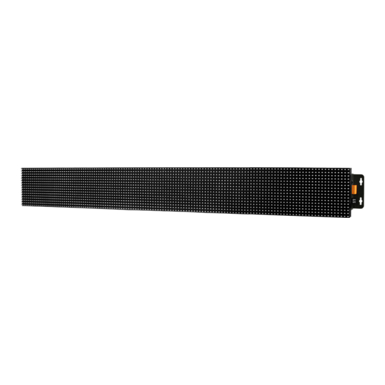
Page 12: Overview
1.3. Overview The iKAN series display is equipped with several interfaces and peripherals that can be integrated with external systems. Here is an overview of the components and its descriptions. Reset Button LED Indicator Ethernet Port (E1 and E2) Terminal Block... - Page 13 The Link is inactive. Green-Blinking Network activity. ● Terminal Block The iKAN series display has a terminal block. The label contents for the terminal block with 20 poles are shown below. For identification of wiring connections, please refer to section “1.4. Wire Connections”...
-
Page 14: Wire Connection
1.4. Wire Connection The iKAN series display has a terminal block which supports several communications. The following figures show the wiring information for the terminal block. RS-232 Wiring RS- 485 Wiring... - Page 15 Wiring Input Type On State as 0 OFF State as 1 Close to GND Open Dry Contact DO Wiring On State OFF State Input Type Readback as 1 Readback as 0 +5 to +24 VDC Open (Sink, NPN)
-
Page 16: Dimension
1.5. Dimension The diagrams below provide details of the dimensions for the iKAN series of displays that can be used when defining the specifications for any enclosures to be installed. All dimensions are in millimeters. iKAN-116S iKAN-124S... - Page 17 iKAN-116 iKAN-124...
- Page 18 iKAN-208 iKAN-216...
- Page 19 iKAN-224...
-
Page 20: Getting Started
2. Getting Started If you are new to iKAN, you should read this chapter first. This chapter provides a description of the basic procedures that need to be followed when installing, configuring, and activating the iKAN system, before operating the iKAN for the first time. 2.1. - Page 21 For two pieces of iKAN display: iKAN-116 and iKAN-216 Two pieces of iKAN Display iKAN-116/iKAN-216 Quick Start Guide …. Wall Mounting Kit * 2 Screw Driver M3x6L Screw iKAN-116: Screw * 14 iKAN-216: Screw * 24 For three pieces of iKAN display: iKAN-124 and iKAN-224 Three pieces of iKAN Display iKAN-116S/iKAN-124S Quick Start Guide...
-
Page 23: Assembling The Ikan
2.2. Assembling the iKAN Before installation, make sure that surface dedicated for installation is suitable to support weight of given device. We do not recommend soft and fragile surfaces, such as polystyrene foam, mineral wool, plaster boards and wooden walls with a thickness of less than 30mm, etc. 2.2.1. -
Page 24: Two Pieces Of Ikan Display Installation
2.2.2. Two Pieces of iKAN Display Installation iKAN-116 and iKAN-216 consists of 2 modules: left end module and right end module. Each row of the module has two connectors for connecting the iKAN display. 1. Pull out the connectors from the opening of the side Left end module Right end module 2. - Page 25 3. Attach the modules and fasten the modules together with 6/8 supplied screws Top View Bottom View Back View...
- Page 26 4. Fasten the left and right mounting plates to the iKAN display with 8/16 supplied screws each side.
-
Page 27: Three Pieces Of Ikan Display Installation
2.2.3. Three Pieces of iKAN Display Installation iKAN-124 and iKAN-224 consists of 3 modules: left end module, middle module and right end module. Each row of the module has two connectors for connecting the iKAN display. 1. Pull out the connectors from the opening of the side Left end module middle module Right end module... - Page 28 2. Connect the connectors and attach the modules Right End Module Left End Module Middle Module...
- Page 29 3. Fasten the modules together with 6/8 supplied screws Top View Bottom View Back View...
- Page 30 4. Fasten the left and right mounting plates to the iKAN display with 8/16 supplied screws each side.
-
Page 31: Connecting To The Power And Pc
2.3. Connecting to the Power and PC The iKAN display has two standard Ethernet ports (RJ-45) which provide access to the iKAN with a PC. To configure the iKAN through the PC, you must establish a connection between the iKAN and a PC. -
Page 32: Connecting The Ikan To A Network
The factory default IP address for each iKAN device is 192.168.255.1. Before integrating an iKAN series display into your network, you should configure the IP, Mask, and Gateway addresses for the device by setting the values that are valid for your network system. - Page 33 3. Once the search process has completed, double-click the name of iKAN display to open the Configure Server (UDP) dialog box 4. Enter the relevant values for the IP Address, Subnet Mask and Gateway, etc., and then click the OK button. The new settings for the iKAN display will take effect within 2 seconds.
-
Page 34: Editing Your First Ikan Message
2.5. Editing Your First iKAN Message The message can be configured using the built-in web interface. To edit your first message, follow the instructions given below. 1. Open a web browser 2. Type the IP address of the iKAN display in the address bar, and then press Enter to display the web interface 3. - Page 35 Select the desired color from the Color drop-down menu iii. Enter the following string in the Message text field: Hello World! iv. Click the Update button Hello World! 6. The IP address for the iKAN series device will be shown on the display. Hello World!
-
Page 36: Configuration
3. Configuration The iKAN series device can be accessed and configured using a standard web-browser (such as Internet Explorer, Firefox, Mac Safari etc) or Internet enabled mobile device. -
Page 37: Web Interface
3.1. Web Interface The iKAN display has a built-in web interface. It provides lots of functions needed to manage all message displayed in iKAN as well as to set up parameters, variables and operation behavior. Most of the common operations can be done by using the iKAN Web Interface. The following table lists the major function of the web interface and provides a link to more information about the function. -
Page 38: Editing And Managing Messages
3.1.1. Editing and Managing Messages A maximum of 128 Common Messages and 20 Instant Messages can be stored on the iKAN series device, and each message can contain a maximum of 40 Unicode characters or 100 ASCII characters. The contents of each common message and instant message can be pre-configured individually via the MESSAGE POOL page on the web interface. -
Page 39: Applying The Variable Maps
3.1.2. Applying the Variable Maps The variable maps provide a mechanism for mapping data to a variable regardless of the data source. The variable maps are listed at the DATA POOL page. The value of most variables can be pre-specified individually via the variable maps. To specify a value to a variable, follow the instructions given below. - Page 40 The configuration area has been registered according to the selected address number. The configuration area provides the following functions: Assign a value to a variable In the text box, enter the relevant values for the selected variable, and then enter the Update button ...
-
Page 41: Mapping Physical Values To Integer-Type Variables
For example, using the range -32768 to 36767 to convert to -10V to +10V. The iKAN series device is able to perform data mapping to translate an integer value that has been read from a remote data source to a readable physical value. -
Page 42: Increasing The Decimal Places For The Number Of Float-Type Variable
3.1.2.2. Increasing the Decimal Places for the Number of Float-Type Variable The number of the decimal places to be used for a float-type variable can be set from the FLOAT VARIABLES page. The offset value is 40128, which means variable 0 is equal to 40128 and variable 2 is equal to 40130, and so on. -
Page 43: Assigning Strings To Coil Variables
3.1.2.3. Assigning Strings to Coil Variables iKAN series devices provide a string mapping function that allows the value of the coil variable to be mapped in order to make the coil value more meaningful when reading the message. The text mapping function allows a maximum of 10 Unicode characters or 30 ASCII characters to be entered to represent a value of 0 or 1. -
Page 44: Importing/Exporting Pre-Configured Messages
3.1.3. Importing/Exporting pre-configured messages If your system contains more than one iKAN series device, it could take a lot of time to configure each one individually. To simplify this process, the Import/Export function that can be used to pre- configure the contents of a message or variable on the iKAN series device before using Modbus TCP/RTU commands to manage the message pool, thereby reducing the need to repeat the configuration tasks multiple times. -
Page 45: Importing A Configuration File
3.1.3.1. Importing a configuration file The contents of a message and variable can be imported to a CSV file. The following is a description of how to import a previously stored configuration file. Note that the Import function will only load configuration information related to messages and variables. 1. -
Page 46: Exporting A Configuration File
3.1.3.2. Exporting a configuration file The contents of a message and variable can be exported as a CSV file. The default file name is msg_con.csv, which can be changed to a preferred file name. 1. Click the SYSTEM menu, and then click the IMPORT/EXPORT menu 2. -
Page 47: Changing The Ip Address
3.1.4. Changing the IP Address The IP address can be changed. To change the IP address, follow the instructions given below. 1. Click the SYSTEM menu, and then click the ETHERNET menu 2. Enter the IP address for the iKAN... -
Page 48: Connecting To A Remote Dl-302 Device
3.1.5. Connecting to a remote DL-302 device The iKAN series devices can be used to display data such as the temperature, humidity and CO2 values sourced from a specific remote DL-302 device that is connected to the same network as the iKAN device. -
Page 49: Setting The Serial Port
3.1.6. Setting the Serial Port The serial port can be set up to establish a connection between the iKAN and the serial I/O devices. The default parameters are 11520 baud, 8 data bits, 1 stop bit, and NO Parity. To set the serial port, follow the instructions given below. -
Page 50: Setting The Modbus Id
3.1.7. Setting the Modbus ID MODBUS ID is the identification for the communication between the iKAN and other devices which use MODBUS protocol. To set the Modbus ID, follow the instructions given below. 1. Click the SYSTEM menu, and then click the Misc. menu 2: Set the Modbus ID, and then click Update button to complete the process... -
Page 51: Adjusting The Led Brightness
3.1.8. Adjusting the LED Brightness 5 levels of brightness are adjustable on the iKAN display. Smaller setting numbers are paired with brighter. To adjust the LED brightness, follow the instructions given below. 1. Click the SYSTEM menu, and then click the Misc. menu 2: In the LED Brightness section, select the setting number from the drop and down menu, and then click the Update button... -
Page 52: Adjusting The Message Motion Speed
3.1.9. Adjusting the Message Motion Speed 10 levels of message motion speed are adjustable on the iKAN display. Smaller setting numbers are paired with higher scrolling speeds. To adjust the message motion speed, follow the instructions given below. 1. Click the SYSTEM menu, and then click the Misc. menu 2: In the Message Motion Speed section, select the setting number from the drop and down menu, and then click the Update button... -
Page 53: Restoring The Default Settings
3.1.10. Restoring the Default Settings This is function to provide a safe reset option for the iKAN display. All messages and variables configuration settings will be reset to factory default. To restore the default settings, follow the instructions given below. 1. -
Page 54: Updating Date And Time
3.1.11. Updating Date and Time This is function to synchronize date and time values on the iKAN display to PC. To synchronize the date and time value with PC, follow the instructions given below. 1. Click the SYSTEM menu, and then click the Misc. menu 2: Scroll down this page until you see the Update Date &... -
Page 56: Resetting The Display
3.1.12. Resetting the Display This function provides a safe reset option for the iKAN display. To reset the display, follow the instructions given below. 1. Click the SYSTEM menu, and then click the Misc. menu 2: Scroll down this page until you see the Software Reset section, and then click the Reset button... -
Page 57: Checking The Firmware Information
1. Click the SYSTEM menu, and then click the Misc. menu 2: Scroll down this page until you see the Module Information section, you can check the version here to see if the iKAN series device needs a firmware update. -
Page 58: Esearch Utility
3.2. eSearch Utility eSearch utility is a program specifically made for the use of products rooted with ICP DAS MiniOS7. Its main functions are to facilitate updating firmware, configuring the Ethernet parameters such as IP address, subnet mask and gateway etc., or updating firmware. The eSearch Utility is developed for searching ICP DAS Ethernet I/O modules based-on MiniOS7 which are connected to the same subnetwork as the Host PC, configuring the Ethernet parameters such as IP address, subnet mask and gateway etc., or updating firmware. -
Page 59: Configuring The Ip Address
3.2.1. Configuring the IP Address The IP address can be changed. To change the IP address, follow the instructions given below. 1. Launch the eSearch utility and click the Search Server button 2. Once the search process has completed, double-click the name of iKAN display to open the Configure Server (UDP) dialog box... - Page 60 3. Enter the relevant values for the IP Address, Subnet Mask and Gateway, etc., and then click the OK button. The new settings for the iKAN display will take effect within 2 seconds.
-
Page 61: Sending The Modbus Command To Ikan
3.2.2. Sending the Modbus Command to iKAN The eSearch Utility has 2 embedded configuration tools, Modbus RTU Master and Modbus TCP Master, which can be used to send the Modbus command to the iKAN display. The Modbus RTU Master tool can be used to send Modbus message to read or write I/O values via the COM port. -
Page 62: Using Modbus Rtu Command To Configure The Ikan Display
3.2.2.1. Using Modbus RTU Command to Configure the iKAN display Before using the Modbus RTU Command tool, iKAN must be configured in Modbus configuration mode. For more information on how to set the iKAN display in Modbus configuration Mode, please refer to Appendix A.1. - Page 63 3. Enter a command in the command line field and then click the Send Command button to transmit the command 4. The command will be displayed on the left-hand side of the text box area, and the response will be shown on the right-hand side of the text box area...
-
Page 64: Using Modbus Tcp Command To Configure The Ikan Display
3.2.2.2. Using Modbus TCP Command to configure the iKAN display Before using the Modbus TCP Command tool, iKAN must be configured in Modbus configuration mode. For more information on how to set the iKAN display in Modbus configuration Mode, please refer to Appendix A.1. - Page 65 3. Enter a command in the command line field and then click the Send Command button to transmit the command 4. The command will be displayed on the left-hand side of the text box area, and the response will be shown on the right-hand side of the text box area...
-
Page 66: Messages
A maximum of 128 Common Messages and 20 Instant Messages can be stored on the iKAN series device, and each message can contain a maximum of 40 Unicode characters or 100 ASCII characters. - Page 67 There are 2 buttons in each message item. button is used to edit the message. button is used to delete the message. By default, the added message has no effect until you add parameters to the message form. Click the button to enter the message form...
- Page 68 The details of these items are as follows: Display Status Enable the contents of the message to be displayed on the iKAN series device. Instant Set this message to be an instant message. Message Moving Mode Specify the message moving mode.
-
Page 69: Displaying Messages With Variables
4.2. Displaying Messages with Variables The iKAN series device allows data related to items such as the Ethernet configuration, the RTC value, and other information, to be inserted into a message as a system variable. The format for using a system variable in a message has a length of 5 bytes as follows:... - Page 70 System variables (3xxxx, 0 based) Modbus Address Length Description Value Range Attribute Decimal Hex. 30000 0000 The IP address for the iKAN 0 ~ 255 series device 30003 0003 30004 0004 The Mask address for the iKAN 0 ~ 255 series device 30007 0007...
- Page 71 30023 0017 Refer to DL series Modbus Address 30001~30007 or 40001~40007 30029 001D Integer-type variables/Float-type variables/misc. (4xxxx, 0 based) Modbus Address Length Description Value Range Attribute Decimal Hex. 40000 0000 Integer-type variables 0 ~ 65535 40063 003F 40128 0080 3.4E+38 ~ +3.4E Float-type variables 40255 00FF...
- Page 72 1: Blue 2: Green 3: Sky Blue 41408 0580 Color for common messages 0 ~ 4: Red 127 at first row. 5: Purple 41535 05FF 6: Yellow 7: White 8: Random Brightness for the display, a 41600 0640 smaller number means a 0 ~ 4 brighter screen Message scrolling speed, a...
- Page 73 41832 0728 ASCII string 1 contents ASCII 41863 0747 41864 0748 ASCII string 2 contents ASCII 41895 0767 41896 0768 ASCII string 3 contents ASCII 41927 0787 41928 0788 ASCII string 4 contents ASCII 41959 07A7 41960 07A8 ASCII string 5 contents ASCII 41991 07C7...
- Page 74 42700 0A8C 4: Red Color for integer variable 0 ~ 63 5: Purple 42763 0ACB 6: Yellow 7: White 42700 0A8C 8: Random Color for float variable 0 ~ 63 42763 0ACB...
-
Page 75: Inserting System Variables Into A Message
4.2.1. Inserting System Variables into a Message The iKAN series device allows data related to items such as the Ethernet configuration, the RTC value, and other information, to be inserted into a message as a system variable. The format for... - Page 76 For example, the following explains how to configure a message to display the IP address for the iKAN series device in message 1. 1. Select the message No. 1, and then click the button 2. Click the button...
- Page 77 Enter the following string in the Message text field: IP: %y000.%y001.%y002.%y003 iv. Click the Update button The IP address for the iKAN series device will be shown on the display. I P : 1 0 . 1 . 0 . 1 0 8...
-
Page 78: Displaying The Current Date And Time
30020 0014 Seconds 0 ~ 59 For example, the following explains how to configure a message to display the current date for the iKAN series device in message 1: 1. Select the message No. 1, and then click the button... - Page 79 %y012/%y013/%y014 %y018 : %y019 iv. Click the Update button %y012/%y013/%y014 %y018 : %y019 The IP address for the iKAN series device will be shown on the display. 2 0 1 6 / 2 / 2 0 1 2 : 0 0...
-
Page 80: Displaying The Co2 And Temperature Values From A Remote Dl-302 Module
For example, the following explains how to configure a message to display the CO2 and temperature data from a remote DL-302 module on the iKAN series device using message 1: 1. Select the message No. 1, and then click the... - Page 81 Click the Update button CO2: %y021 PPM, Temp: %y023 The IP address for the iKAN series device will be shown on the display. CO2: 7 0 2 P P M , T e m p : 2 5 °C...
-
Page 82: Inserting Integer-Type Variables Into A Message
Character 3-digit decimal number u: Unsigned integer (0~65535) i: Signed integer (-32768~32767) A maximum of 64 integer variables can be stored on the iKAN series device, and are accessed using Modbus register addresses 40000 to 40063. Modbus Address Length Description... - Page 83 For example, the following explains how to insert a signed type integer variable into Modbus register 40001 using message address 1. 1. Select the message No. 1, and then click the button 2. Click the button...
- Page 84 The value for integer variable 1 will be shown on the iKAN display. Input Voltage: 32767 V iKAN series devices provide the data mapping function for Integer-type variables, please refer to section “4.3.1. Displaying the Mapping Data for Integer-type Variables” for more details.
-
Page 85: Inserting Float-Type Variables Into A Message
Variable Type Character 3-digit decimal number f: Float variable (-3.4E+38 ~ +3.4E+38) A maximum of 64 float variables can be stored on the iKAN series device, and are accessed using Modbus register addresses 40000 to 40063. Modbus Address Length Description... - Page 86 For example, the following explains how to insert a float-type variable into Modbus register 40130 using message address 1. 1. Select the message No. 1, and then click the button 2. Click the button...
- Page 87 The value for float-type variable 1 will be shown on the iKAN display. Pressure: 0.9 bars iKAN series devices allow the number of decimal places increased for Float-type variables, please refer to section “4.3.2. Displaying the Number with Increased Decimal Places for Float-Type...
-
Page 88: Inserting Coil -Type Variables Into A Message
3 to 5 Delimiter Character Variable Type Modbus Address: 3-digit decimal number b: Coil A maximum of 40 Coil type variables can be stored on the iKAN series device, and are accessed using Modbus register addresses 00000 to 00039. Modbus Address Value... - Page 89 For example, the following explains how to insert a coil variable into Modbus register 00000 using message 1: 1. Select the message No. 1, and then click the button 2. Click the button...
- Page 90 The value for Coil variable 1 will be shown on the iKAN display. Coil variable 0 = 1 iKAN series devices provide a string mapping function that allows the value of the coil variable to be mapped, please refer section “4.3.3. Displaying the Value of a Coil with the Replacement Text”...
-
Page 91: Inserting Ascii Strings Into A Message
3 to 5 Delimiter Character Variable Type Modbus Address: 3-digit decimal number a: ASCII string A maximum of 64 float variables can be stored on the iKAN series device, and are accessed using Modbus register addresses 40000 to 40063. Modbus Address Length... - Page 92 ASCII 42055 0808 For example, the following explains how to configure a message to display the current date for the iKAN series device in the message at address 1: 1. Select the message No. 1, and then click the button...
- Page 93 2. Click the button 3. In the No. 1 form, specify the following parameters: i. Check the Display Status checkbox ii. Select the desired color from the Color drop-down menu iii. Enter the following string in the Message text field: iv.
-
Page 94: Displaying The Value Applied With The Variable Map
4.3. Displaying the Value Applied with the Variable Map The variable maps provide a mechanism for mapping data to a variable regardless of the data source. The variable maps are listed at the DATA POOL page. The value of most variables can be pre- specified individually via the variable maps. -
Page 95: Displaying The Mapping Data For Integer-Type Variables
For example, using the range -32768 to 36767 to convert to -10V to +10V. The iKAN series device is able to perform data mapping to translate an integer value that has been read from a remote data source to a readable physical value. - Page 96 2. Considering the arguments for data mapping Target High Source Low Source High Target Low For example, to convert a 16-bit unsigned integer (0 to 65535) to the voltage 0 to 10 V, set the following arguments: Argument Value Description Source Low The minimum value of the integer Target Low...
- Page 97 3. Enter the following value, and then click the Update button i. In the Source Low column, enter the minimum value of the integer value. ii. In the Source High column, enter the maximum value of the integer value. iii. In the Target Low column, enter the minimum value of the physical value. iv.
-
Page 98: Displaying The Number With Increased Decimal Places For Float-Type Variables
4.3.2. Displaying the Number with Increased Decimal Places for Float-Type Variables The number of the decimal places to be used for a float-type variable can be set from the FLOAT VARIABLES page. The offset value is 40128, which means variable 0 is equal to 40128 and variable 2 is equal to 40130, and so on. - Page 99 The value for float-type variable 1 will be shown on the iKAN display using the specified number of decimal places. Pressure: 0.9 bars Pressure: 0.981 bars...
-
Page 100: Displaying The Value Of A Coil Variable With The Replacement Text
The text mapping function allows a maximum of 10 Unicode characters or 30 ASCII characters to be entered to represent a value of 0 or 1. - Page 101 For example, the following explains how to configure the text mapping for the Coil variable at address 1. This example is a continuation of the example in section 4.2.4. 1. Click the address 1 option, and then click the Adv. Config button 2.
- Page 102 The value for coil variable 1 is now replaced by the mapping text on the display. Coil variable 0 = 1 Coil variable 0 = Operating...
-
Page 103: Ikan Updates
5. CANopen Communication... - Page 104 5.1. Feature Software CANopen version: DS-301 v4.01. Support NMT slave. Support Node Guarding for Error Control. Support Node ID and Baud Rate configuration for LSS. Default Node ID: 1, Baud Rate: 500Kbps Support Emergency Message. ...
- Page 105 5.2. Object Dictionary...
- Page 106 5.2.1. Communication Profile Area General Communication Entries The following information lists each entry into the communication profile area defined in iKAN-XXX-CPS. In order to look up the entries conveniently, we divide them into two tables. They are “General Communication Entries” and “SDO Communication Entries”. In the table header you can see “Idx”, “Sidx”...
- Page 107 Note: 1. The object with index 0x1000 has the following data format: Additional information General Information bit 31~ bit 24 bit 23 ~ bit16 bit 15 ~ bit 0 Specific functionality I/O functionality Device profile number For iKAN-XXX-CPS, the specific functionality is always 0. The I/O functionality defines what kind of device the iKAN -7232D is.
- Page 108 time is ms. SDO Communication Entries Sidx Description Type Attr Default 1200h largest sub-index supported for UNSIGNED 8 “server SDO parameter” COB-ID form client to server UNSIGNED 32 600h+Node-ID (RxSDO) COB-ID form server to client UNSIGNED 32 580h+Node-ID (TxSDO)
- Page 109 5.2.2. Standardize Device Profile Area Digital Input Device Entries Sidx Description Type Attr Default 6000h Number of DI in iKAN UNSIGNED 8 DI-1 UNSIGNED 8 (0x01) DI-2 UNSIGNED 8 (0x02) Digital Output Device Entries Sidx Description Type Attr Default 6200h Number of Coil-type...
- Page 110 IP Address #2 UNSIGNED 8 (0xA8) IP Address #3 UNSIGNED 8 (0xFF) IP Address #4 UNSIGNED 8 (0x01) Analog Output Device Entries Sidx Description Type Attr Default 6411h Number of Integer-type UNSIGNED 8 Variables (0x40) Integer-type Variables UNSIGNED 16 (0x01) Integer-type Variables UNSIGNED 16...
- Page 111 Message #1 UNSIGNED 16 Color Setting in Second Message #2 UNSIGNED 16 Color Setting in Second … UNSIGNED 16 Message #128 UNSIGNED 16 (0x80) Color Setting in Second 6415h Number of Message UNSIGNED 8 Priority Setting (0x80) Message #1 UNSIGNED 16 Priority Setting Message #2 UNSIGNED 16...
- Page 112 DL-300 series device The response timeout UNSIGNED 16 value for Modbus TCP communication The Delay between polls UNSIGNED 16 value for Modbus TCP communication 6417h Nunber of Integer Data UNSIGNED 8 mapping arguments: (0x40) Source Low Integer #1 mapping UNSIGNED 16 arguments: Source Low Integer #2 mapping UNSIGNED 16...
- Page 113 Target High Integer #1 mapping UNSIGNED 16 arguments: Target High Integer #2 mapping UNSIGNED 16 arguments: Target High … UNSIGNED 16 Integer #64mapping UNSIGNED 16 (0x40) arguments: Target High 641Bh Nunber of Integer Data UNSIGNED 8 mapping arguments: (0x40) Decimal Integer #1 mapping UNSIGNED 16 arguments: Decimal...
- Page 114 … UNSIGNED 16 Coil #40 Color setting UNSIGNED 16 641Fh Nunber of Color for UNSIGNED 8 Integer variable (0x40) Integer #1 Color setting UNSIGNED 16 Integer #2 Color setting UNSIGNED 16 … UNSIGNED 16 Integer #64Color setting UNSIGNED 16 (0x40) 6420h Nunber of Color for Float UNSIGNED 8...
- Page 115 1~254 0~65535 0(disable) or 1(Enable) 0~255 0~255 0~255 0~255 10(0x0A) 0~65535 11(0x0B) 1~247 12(0x0C) 0~65535 13(0x0D) 0~65535 0x6417 1~64(0x40) 0~65535 0x6418 1~64(0x40) 0~65535 0x6419 1~64(0x40) 0~65535 0x641A 1~64(0x40) 0~65535 0x641B 1~64(0x40) 0x641C 1~64(0x40) 0x641D 1~128(0x80) 0x641E 1~40(0x28) 0(red),1(green),2(yellow),3(blue),4(purple),5(sky blue),6(white),7(random) 0x641F 1~64(0x40) 0(red),1(green),2(yellow),3(blue),4(purple),5(sky blue),6(white),7(random)
- Page 116 5.3. Application...
- Page 117 5.3.1. Digital Output The iKAN series provide the function for digital output access. The iKAN-XXX-CPS module uses object index 0x6200 and its sub-index to access the digital output. The total of digital output is 171 bytes. They consist of four parts, including Coil type variable, Enable/Disable Display of Message, digital output, Software reset.
- Page 118 Length SDO server SDO client (iKAN) 11-bit COB-ID (bit) Data 8-byte Data (byte) Func Code Node ID Length SDO server SDO client (iKAN) After reading sub-index 0x01 – 0x04, the users will get the fully IP address of iKAN series.
- Page 119 Func Code Node ID Length SDO server SDO client (iKAN) Note: the integer-type variable in iKAN series is distinguished to signed integer and unsigned integer. Before using iKAN-XXX-CPS to access integer-type variables, please remind the range of the integer value.
- Page 120 5.3.4. Float‐type variables The iKAN series provide the function for float-type variables access. The iKAN-XXX-CPS module uses object index 0x6412 and its sub-index to access the float -type variables. Function Size Value Range Sub-Index Float -type variable #1 1 word 0 –...
- Page 121 5.3.5. Message Color in First Row The iKAN series provide the function for message color in first row control. The iKAN-XXX-CPS module uses object index 0x6413 and its sub-index to access the message priority control. 功能 大小 數值範圍 子索引 Message#1 Color in First Row 1 word 0 –...
- Page 122 5.3.6. Message Color in Second Row The iKAN series provide the function for message color in second row control. The iKAN-XXX-CPS module uses object index 0x6414 and its sub-index to access the message priority control. 功能 大小 數值範圍 子索引 Message#1 Color in First Row 1 word 0 –...
- Page 123 SDO server SDO client (iKAN)
- Page 124 5.3.7. Message Priority The iKAN series provide the function for message priority control. The iKAN-XXX-CPS module uses object index 0x6413 and its sub-index to access the message priority control. Function Size Value Range Sub-Index Message #1 priority 1 word 0 or 1...
- Page 125 5.3.8. Message Moving Type The iKAN series provide the function for message moving type control. The iKAN-XXX-CPS module uses object index 0x641D and its sub-index to access the message moving type. Function Size Value Range Sub-Index Message #1 moving type...
- Page 126 5.3.9. Others Message Control Variables The iKAN series provide the function for message control, including brightness of display change, and message scrolling speed change. The iKAN-XXX-CPS module uses object index 0x6416 and its sub-index to access the message control variables.
- Page 127 SDO server SDO client (iKAN) 11-bit COB-ID (bit) 8-byte Data (byte) Data Func Code Node ID Length SDO server SDO client (iKAN)
- Page 128 5.3.10. Argument of Integer-Type Variable The iKAN series provide the function for argument of integer-type variable. The arguments include source low, source high, target low, target high, decimal, color. The iKAN-XXX-CPS module uses object index 0x6417, 0x6418, 0x6419, 0x641A, 0x641B, and their sub-index to implement the function.
- Page 129 Set source high 100: 11-bit COB-ID (bit) 8-byte Data (byte) Data Func Code Node ID Length SDO server SDO client (iKAN) 11-bit COB-ID (bit) 8-byte Data (byte) Data Func Code Node ID Length SDO server SDO client (iKAN) Set target low 0: 11-bit COB-ID (bit) 8-byte Data (byte) Data...
- Page 130 SDO server SDO client (iKAN) 11-bit COB-ID (bit) 8-byte Data (byte) Data Func Code Node ID Length SDO server SDO client (iKAN) Set decimal 1: 11-bit COB-ID (bit) Data 8-byte Data (byte) Func Code Node ID Length SDO server SDO client (iKAN) 11-bit COB-ID (bit) 8-byte Data (byte)
- Page 131 Func Code Node ID Length SDO server SDO client (iKAN) 11-bit COB-ID (bit) Data 8-byte Data (byte) Func Code Node ID Length SDO server SDO client (iKAN) Note: After using these commands, if integer#1 is 50, it will become 500.0 on iKAN.
- Page 132 5.3.11. Argument of Float-Type Variable The iKAN series provide the function for argument of float-type variable. The arguments include decimal and color. The iKAN-XXX-CPS module uses object index 0x641C, 0x6420, and their sub- index to implement the function. Function Size...
- Page 133 Func Code Node ID Length SDO server SDO client (iKAN) 11-bit COB-ID (bit) Data 8-byte Data (byte) Func Code Node ID Length SDO server SDO client (iKAN)
- Page 134 5.3.12. ASCII String The iKAN series provide the function that allow the Host PC or a PLC to write real-time ASCII string via the CANopen protocol. The iKAN-XXX-CPS module uses object index 0x6421 and its sub- index to implement the function.
- Page 135 Func Code Node ID Length SDO server SDO client (iKAN) Send (Data0=10) + (Data1~7=ASCII String data) 11-bit COB-ID (bit) 8-byte Data (byte) Data Func Code Node ID Length SDO server SDO client (iKAN) 11-bit COB-ID (bit) 8-byte Data (byte) Data Func Code Node ID Length...
- Page 136 SDO server SDO client (iKAN) Following is the sent commands and response. Commands: Response:...
- Page 137 5.4. LSS communication set The iKAN-XXX-CPS module not supports the hardware and the software to change Node ID or CAN baud rate settings, such as rotary switch and utility. For this reason, we use the LSS protocol of CANopen to implement the function for change Node ID setting and CAN baud rate setting via CAN bus of the iKAN-XXX-CPS module.
- Page 138 The command below is used to get the current Node ID setting from the module. Before changing the Node ID, please remind the original Node ID setting. 11-bit COB-ID (bit) 8-byte Data (byte) Data Func Code Node ID Length LSS Slave Master (iKAN) COB_ID...
- Page 139 COB_ID 0x7E5 LSS-Msg cs: the LSS command specifier. cs = 0x11 for changing Node ID. ID: the new Node ID value. 11-bit COB-ID (bit) Data 8-byte Data (byte) Func Code Node ID Length Err1 Err2 LSS Slave Master (iKAN) COB_ID 0x7E4 LSS-Msg cs: the LSS command specifier.
- Page 140 11-bit COB-ID (bit) 8-byte Data (byte) Data Func Code Node ID Length Tab1 Tab2 LSS Slave Master (iKAN) COB_ID 0x7E5 LSS-Msg cs: the LSS command specifier. cs = 0x13 for changing baud rate. Tab1: the standardized CiA bit timing table (reserved). Tab2: the value of table index.
- Page 141 LSS-Msg cs: the LSS command specifier. cs = 0x17 for configuration store. 11-bit COB-ID (bit) 8-byte Data (byte) Data Func Code Node ID Length Err1 Err2 LSS Slave Master (iKAN) COB_ID 0x7E4 LSS-Msg cs: the LSS command specifier. CS = 0x17 for configuration store. Err1: error code.
- Page 142 5.5. EMCY Communication set...
- Page 143 5.5.1. EMCY COB_ID Parameter The EMCY COB-ID is similar to the PDO COB-ID. It can be a default value or be defined by users via SDO communication methods. This COB-ID is stored in the object 0x1014, and the data format is shown in the following table.
- Page 144 5.5.2. EMCY Communication The EMCY message is triggered when some internal error occurs. After the transmission of one EMCY message, the object with index 0x1003 will record this EMCY event. Therefore, the users can check this object to understand the history of the error’s occurrences. The iKAN-XXX-CPS supports a max of 5 records stored in the different sub-indexes of the index 0x1003 object.
- Page 145 Manufacturer specific Emergency Manufacturer Error Code Specific Error Field Error Last Description High Register First two three Byte Byte Byte Byte 00 00 00 Error Reset or No Error 00 00 00 CAN Controller Error Occur 00 00 00 EEPROM Access Error 00 00 00 COM Port Access Error 00 00 00...
- Page 146 5.6. NMT Communication Set...
- Page 147 5.6.1. Module Control Protocol The NMT communication set can be applied for changing the NMT status of the NMT slave. The following figure shows how to change the different NMT statuses for the iKAN-XXX-CPS. Start Remote Node Protocol NMT Slave NMT Master Indication Request...
- Page 148 NMT Slave NMT Master Indication Request Indication Indication Enter Pre-operational Protocol : NMT command specifier. cs = 128, remote node enters pre-operational. Node ID : the node ID of the NMT slave device. Reset Node Protocol NMT Master NMT Slave Indication Request Indication...
- Page 149 5.6.2. Error Control Protocol Error Control Protocol is one of the ways to check if the CANopen device still lives. Related objects are indexes 0x100C and 0x100D. The 0x100C is the guard time, and the 0x100D is the Life Time factor. The node Life Time is the guard time multiplied by the Life Time factor. The Node Guarding timer of the iKAN-XXX-CPS starts to count after receiving the first remote- transmit-request for the guarding identifier.
- Page 150 For more easily operate the iKAN-XXX-CPS module, we provide the demo program and show how to control iKAN series via CANopen protocol. The demo is drove by Virtaul CAN driver. Thus, before using this demo, please install Virtual CAN driver first. Virtual CAN is a technique which is used to simulate CAN ports on PC via Virtual CAN driver.
- Page 151 CANopen command method to show how to use these functions. IP Address This function is used to get the IP address of iKAN series. Common Configuration This function is used to change the brightness and moving speed.
- Page 152 Second Row Color: This field is used to decide the color in second row of the message which is chosen. Note: If users want to use this function, users need to set to display two rows on the web of iKAN series.
- Page 153 Moving Type: This field is used to decide the way that how the message moves. Coil This function is used for changing Coil type variable. No.: The coil type variable which will be configure. The iKAN-XXX-CPS supports to control 40 coil type variables.
- Page 154 The number of decimal places that will show on the display. Integer This function is used to change integer-type value and configuration. No.: The integer type variable which will be configure. The iKAN-XXX-CPS supports to control 32 integer type variables. ...
- Page 155 Monitor Page Monitor Coil Type Variable Monitor Integer Type Variable...
- Page 156 Monitor Float Type Variable...
- Page 157 ICP DAS will continue to update the iKAN firmware for more useful functions and better performance. The latest firmware can be obtained from: http://ftp.icpdas.com/pub/cd/ikan/firmware/ The firmware version is listed at the bottom of the MISC.page. You can check the version here to see if the iKAN series device needs a firmware update.
- Page 158 7188xw Utility is a Win32 console program used to update OS image and firmware. It uses the COM port to communicate with the connected module. 1. Connect the RS-232 port on the iKAN to the RS-232 port on the PC RS-232 RS-232 2.
- Page 159 4. Open the command prompt and change the current directory to the directory where the firmware is located 5. Enter command “7188xw /c1 /b115200 /n81” to execute the 7188xw Utility 6. Press the Enter to connect to the iKAN and press the F9 to download the firmware to iKAN 7.
-
Page 160: Appendix A. How To
Appendix A. How to – A.1. How to set iKAN Display in Modbus Configuration Mode Before using the Modbus RTU/TCP Command tool, iKAN must be configured in Modbus configuration mode. To configure iKAN into a Modbus configuration mode, follow the instructions given below. -
Page 161: Appendix B. Variable Types And Modbus Register Map
Appendix B. Variable Types and Modbus Register Map B.1. Variable Types The iKAN series device allows data related to items such as the Ethernet configuration, the RTC value, and other information, to be inserted into a message as a system variable. -
Page 162: Modbus Register Map
B.2. Modbus Register Map Coil-type variables (0xxxx, 0 based) Modbus Address Value Length Description Attribute Decimal Hex. Range 00000 0000 Coil-type variables 00039 0027 00100 0064 Enables or disables the display of 0: Disabled common messages 0 ~ 127. 1: Enabled 00227 00E3 System variables (3xxxx, 0 based) - Page 163 Wednesday, Thursday, Friday, Saturday Day of the week in Chinese characters: 30017 0011 0 ~ 6 日、一、二、三、四、五、 六 30018 0012 Hours (24-hour format) 0 ~ 23 30019 0013 Minutes 0 ~ 59 30020 0014 Seconds 0 ~ 59 DL series module name (low 30021 0015 0x0301~0x0302...
- Page 164 40475 023F 40640 0280 Data mapping arguments: 0 ~ 65535 Target Low 40703 02BF 40768 0300 Data mapping arguments: 0 ~ 65535 Target High 40831 033F 40896 0380 Data mapping arguments: 0 ~ 2 Decimal Places 40959 03BF 41024 0400 Decimal Places for float-type 1 ~ 3 variables...
- Page 165 The Modbus TCP port for the 41610 0650 0~65535 DL-300 series device The Modbus TCP ID for the DL- 41611 0651 1~247 300 series device The response timeout value for 41612 0652 0~65535 Modbus TCP communication The Delay between polls value 41613 0653 0~65535...
- Page 166 42055 0808 1: Blue 2: Green 3: Sky Blue 42100 0834 Color for messages 0 ~ 127 at 4: Red second row. 5: Purple 42227 08B3 6: Yellow 7: White 8: Random 42300 08FC Message moving type for 0:Common messages 0 ~ 127 1:Instant 42427 097B...
-
Page 167: Appendix B. Revision History
Appendix B. Revision History This chapter provides revision history information to this document. The table below shows the revision history. Revision Date Description 1.0.1 May 2019 Initial issue...
Need help?
Do you have a question about the iKAN Series and is the answer not in the manual?
Questions and answers