Advertisement
Table of Contents
- 1 Packing List
- 2 Overview
- 3 Installing the Waterproof Assembly
- 4 Connecting the Power Connector
- 5 Connecting the RJ-45 Connector
- 6 Installing, Wiring and Connecting the I/O Connector
- 7 RJ-45 Ethernet Waterproof Installation Guide
- 8 Steps for RJ-45 Ethernet Waterproof Installation
- Download this manual
Packing List
In addition to this guide, the package includes the following items:
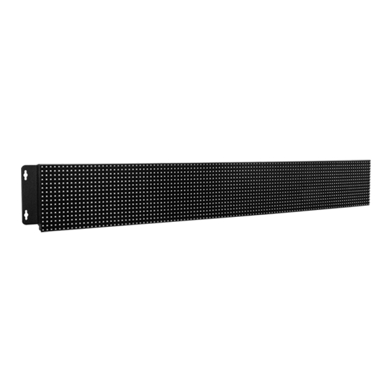
iKAN-116A-IP65/
iKAN-124A-IP65 LED Display
RJ-45 Connector x 2
Waterproof Assembly
Technical Support
service@icpdas.com
www.icpdas.com
Installation Guide
For Desktop Web
iKAN-116A-IP65/iKAN-124A-IP65 Quick Start
CA-M12-02
Power Cable
Resources
How to search for drivers, manuals and
spec information on ICP DAS website.
For Mobile Web
Model
Name
Wall Mounting
Kit x 2
Model
Name
v2.0, March 2022
M4x6L
Screw x 8
CA-039
I/O Cable
Screw
Driver
P1
Advertisement
Table of Contents

Related Manuals for ICP DAS USA iKAN-116A-IP65


Summary of Contents for ICP DAS USA iKAN-116A-IP65
- Page 1 Quick Start v2.0, March 2022 Packing List In addition to this guide, the package includes the following items: iKAN-116A-IP65/ Wall Mounting M4x6L iKAN-124A-IP65 LED Display Kit x 2 Screw x 8 RJ-45 Connector x 2 CA-M12-02 CA-039 Screw Driver...
- Page 2 Power Connector Installing the Waterproof Assembly The waterproof Assembly can effectively protect the connection points from weather and climate. The iKAN-116A-IP65/iKAN-124A-IP65 LED display is equipped with two RJ-45 waterproof connectors that are optional for use with E1 and E2 port.
- Page 3 Connecting the Power Connector The iKAN-116A-IP65/iKAN-124A-IP65 LED display is equipped with a power cable, to insert the power cable into the receptacle. Here we recommend that you install a breaker (5V, 30A) between the DC power supply and the iKAN LED Display. Refer to the wiring diagram below for details.
- Page 4 Installing, Wiring and Connecting the I/O Connector The iKAN-116A-IP65/iKAN-124A-IP65 LED display is equipped with an I/O cable that provides access to RS-232, RS-485 and digital I/O signals. Wiring and Insert the I/O cable into the receptacle RS-232 x 1 RS-485 x2...
- Page 5 RJ-45 Ethernet Waterproof Installation Guide v1.1, March 2022 1. Remove the RJ-45 connector from the RJ-45 cable 2. Feed the end of the RJ-45 cable through the Sealing Nut, Seal, Screw Nut, Clamping Ring and Gasket Screw Clamping Gaske Seal Ring Sealing 3.
- Page 6 4. Wrap the Screw Nut around the Clamping Ring 5. Insert the Seal into the Clamping Ring 6. Push the Sealing Nut forward and Hand-tighten it to seal the assembly 7. Insert the RJ-45 cable into the RJ-45 connector...
Need help?
Do you have a question about the iKAN-116A-IP65 and is the answer not in the manual?
Questions and answers