Chapters
Table of Contents
Troubleshooting

Related Manuals for IEI Technology ECW-281B-D525


Summary of Contents for IEI Technology ECW-281B-D525
- Page 1 ECW-281B/B2-D525 Embedded System ECW-281B/B2-D525 Embedded System MODEL: MODEL: ECW-281B/B2-D525 IEI Intel® Atom™ Fanless Embedded System RoHS Compliant, Dual GbE LAN, COM Ports, USB 2.0 User Manual Page i Rev. 1.04 – March 12, 2015...
- Page 2 ECW-281B/B2-D525 Embedded System Revision Date Version Changes March 12, 2015 1.04 Changed the label of the on-board RS-232/422/485 connector from COM2 to COM6. October 19, 2012 1.03 Added bottom cover screw torque warning October 24, 2011 1.02 Modified COM port locations in Section 2.3.2 Updated Chapter 5: BIOS May 17, 2011...
- Page 3 ECW-281B/B2-D525 Embedded System Copyright COPYRIGHT NOTICE The information in this document is subject to change without prior notice in order to improve reliability, design and function and does not represent a commitment on the part of the manufacturer. In no event will the manufacturer be liable for direct, indirect, special, incidental, or consequential damages arising out of the use or inability to use the product or documentation, even if advised of the possibility of such damages.
- Page 4 ECW-281B/B2-D525 Embedded System WARNING This device complies with Part 15 of the FCC Rules. Operation is subject to the following two conditions: (1) this device may not cause harmful interference, and(2) this device must accept any interference received, including interference that may cause undesired operation. NOTE: This equipment has been tested and found to comply with the limits for a Class B digital device, pursuant to part 15 of the FCC Rules.
-
Page 5: Table Of Contents
IMENSIONS 2.3 E ....................10 XTERNAL VERVIEW 2.3.1 Front Panel ...................... 10 2.3.2 Rear Panel ....................... 10 2.3.2.1 ECW-281B-D525 Rear Panel ..............10 2.3.2.2 ECW-281B2-D525 Rear Panel ..............11 2.3.3 Bottom Surface....................12 2.4 I ....................13 NTERNAL VERVIEW 3 SYSTEM COMPONENTS ..................14 3.1 E... - Page 6 4.2.4.1 Jumpers ..................... 34 4.2.4.2 CF Card Setup................... 35 4.2.4.3 Clear CMOS Jumper................. 35 4.2.4.4 COM 6 Function Select Jumper (ECW-281B-D525 Series Only) ... 37 4.2.4.5 COM 1 Pin 9 Setting Jumper ..............38 4.2.5 Hard Drive Installation..................39 4.2.6 Mounting the System with Mounting Brackets..........42 4.2.7 Mounting the System with Wall Mount Kit............
- Page 7 ECW-281B/B2-D525 Embedded System 5.1.3 Getting Help..................... 52 5.1.4 Unable to Reboot After Configuration Changes..........52 5.1.5 BIOS Menu Bar....................52 5.2 M ........................53 5.3 A ....................... 54 DVANCED 5.3.1 ACPI Configuration ..................54 5.3.2 CPU Configuration..................56 5.3.3 IDE Configuration ................... 57 5.3.4 USB Configuration...................
- Page 8 ECW-281B/B2-D525 Embedded System A.1.2 Anti-static Precautions ..................87 A.1.3 Product Disposal ..................... 88 A.2 M ............88 AINTENANCE AND LEANING RECAUTIONS A.2.1 Maintenance and Cleaning................88 A.2.2 Cleaning Tools ....................89 B BIOS MENU OPTIONS ..................... 90 B.1 BIOS C ................
- Page 9 Figure 1-1: ECW-281B/B2-D525 Series Embedded System ............2 Figure 1-2: Power Adapter......................7 Figure 2-1: ECW-281B/B2-D525 Dimensions (mm) ..............9 Figure 2-2: ECW-281B/B2-D525 Front Panel................10 Figure 2-3: ECW-281B-D525 Rear Panel..................11 Figure 2-4: ECW-281B2-D525 Rear Panel ..................12 Figure 2-5: Bottom Surface ......................13 Figure 2-6: Internal Overview ......................13 Figure 3-1: WAFER-PV-D5252 Jumper and Connector Locations ..........15...
- Page 10 ECW-281B/B2-D525 Embedded System Figure 4-12: Wall-mounting Bracket ...................43 Figure 4-13: Mount the Embedded System................44 Figure 4-14: DIN Rail Mounting Bracket ..................45 Figure 4-15: Screw Locations......................45 Figure 4-16: Mounting the DIN RAIL ...................46 Figure 4-17: Secure the Assembly to the DIN Rail ..............46 Figure 4-18: Wireless Antenna Installation................47 Figure 4-19: Terminal Block Pinouts ..................48 Figure 4-20: Power Button......................49...
- Page 11 ECW-281B/B2-D525 Embedded System List of Tables Table 1-1: Model Variations ......................3 Table 1-2: Technical Specifications....................5 Table 1-3: DC-to-DC Power Module Specifications..............6 Table 1-4: Power Adapter Specifications ..................7 Table 3-1: Peripheral Interface Connectors ................17 Table 3-2: ATX Power Connector Pinouts .................18 Table 3-3: Audio Connector Pinouts (10-pin) ................18 Table 3-4: CF Card Socket Pinouts.....................20 Table 3-5: LED Connector Pinouts .....................21...
- Page 12 ECW-281B/B2-D525 Embedded System List of BIOS Menus BIOS Menu 1: Main ........................53 BIOS Menu 2: Advanced ......................54 BIOS Menu 3: ACPI Configuration ....................55 BIOS Menu 4: CPU Configuration ....................56 BIOS Menu 5: IDE Configuration....................57 BIOS Menu 6: USB Configuration ....................58 BIOS Menu 7: Super IO Configuration..................59 BIOS Menu 8: Serial Port n Configuration Menu...............60 BIOS Menu 9: Hardware Health Configuration ................65...
-
Page 13: Introduction
ECW-281B/B2-D525 Embedded System Chapter Introduction Page 1... -
Page 14: Overview
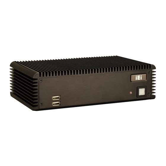
ECW-281B/B2-D525 Embedded System 1.1 Overview Figure 1-1: ECW-281B/B2-D525 Series Embedded System There are four WAFER-PV-D5252 Intel® Atom™ based embedded solutions in the ECW-281B/B2-D525 series. All fanless motherboards have been optimized for multimedia PV-D5252 applications that require minimum installation space. The WAFER- motherboard supports a full range of functions for an AT/ATX-compatible industrial computer. -
Page 15: Model Variations
ECW-281B/B2-D525 Embedded System Dual GbE LAN for high speed network applications One SATA hard drive supported Wall mount and DIN mount supported. 1.2 Model Variations There are six models in the ECW-281B/B2-D525 embedded system series. The six models are all preinstalled with an Intel®... -
Page 16: Technical Specifications
ECW-281B/B2-D525 Embedded System 1.3 Technical Specifications The specifications for the Intel based embedded systems are listed below. ECW-281B-D525 ECW-281B2-D525 Preinstalled 1.8 GHz Intel® Atom™ Processor D525 with 1 MB L2 cache System Chipset Intel® ICH8M System Memory Preinstalled 1.0 GB DDR3 SDRAM SO-DIMM (system max. 2 GB) -
Page 17: Table 1-2: Technical Specifications
ECW-281B/B2-D525 Embedded System -20ºC ~ 65ºC with SATA SSD, air flow* Operating Temperature -10ºC ~ 50ºC with SATA HDD in wireless model, air flow* *Ambient air speed per IEC-68-2-2 standard Color Black DIN mount Mounting VESA MIS-D 75 wall mount Weight (Net/Gross) 2.1 kg/3.9 kg Dimensions (D x W x H) -
Page 18: Power Module Specifications (Optional)
ECW-281B/B2-D525 Embedded System 1.4 Power Module Specifications (Optional) A DC-to-DC power module is preinstalled in the WD series model to provide 9 V~36 V power input. The specifications for the IDD-936260A are shown in T able 1-3. 6 5 4 Model Name: IDD-936260A Input... -
Page 19: Power Adapter (Optional)
ECW-281B/B2-D525 Embedded System 1.5 Power Adapter (Optional) The ECW-281B/B2-D525 series models that feature 12 V DC input are shipped with a 60W power adapter. Figure 1-2: Power Adapter The specifications for the adapter are listed in T able 1-4: 6 5 4 90 V ~ 264 V AC Input Voltage 47 Hz ~ 63 Hz... -
Page 20: Mechanical Description
ECW-281B/B2-D525 Embedded System Chapter Mechanical Description Page 8... -
Page 21: Mechanical Overview
ECW-281B/B2-D525 Embedded System 2.1 Mechanical Overview The ECW-281B/B2-D525 RoHS compliant, Intel® Atom™ fanless embedded system features industrial grade components that offer longer operating life, high shock/vibration resistance and endurance over a wide temperature range. The ECW-281B/B2-D525 combines these features in an aluminum enclosure. Featuring two LAN, four USB, six serial communication ports, as well as audio, and VGA, the ECW-281B/B2-D525 offers system integrators and developers the best selection of robust and high performance computing system platforms. -
Page 22: External Overview
F igure 2-2 below. 6 5 4 Figure 2-2: ECW-281B/B2-D525 Front Panel 2.3.2 Rear Panel 2.3.2.1 ECW-281B-D525 Rear Panel The rear panel of the ECW-281B-D525 provides access to the following external I/O connectors. 2 x USB port connectors ... -
Page 23: Ecw-281B2-D525 Rear Panel
1 x Wireless antenna connector (for wireless models only) An overview of the rear panel is shown in F igure 2-3. 6 5 4 Figure 2-3: ECW-281B-D525 Rear Panel 2.3.2.2 ECW-281B2-D525 Rear Panel The rear panel of the ECW-281B2-D525 provides access to the following external I/O connectors. -
Page 24: Bottom Surface
ECW-281B/B2-D525 Embedded System An overview of the rear panel is shown in F igure 2-4. 6 5 4 Figure 2-4: ECW-281B2-D525 Rear Panel 2.3.3 Bottom Surface WARNING: Never remove the bottom access panel from the chassis while power is still being fed into the system. -
Page 25: Internal Overview
ECW-281B/B2-D525 Embedded System Figure 2-5: Bottom Surface 2.4 Internal Overview The ECW-281B/B2-D525 internal components are listed below: 1 x IEI WAFER motherboard (preinstalled) 1 x IEI power module (WD modesls only) 1 x SO-DIMM module (preinstalled) 1 x Hard drive bracket and SATA cable support one SATA hard disk All the components are accessed by removing the bottom surface. -
Page 26: System Components
ECW-281B/B2-D525 Embedded System Chapter System Components Page 14... -
Page 27: Embedded System Motherboard
ECW-281B/B2-D525 Embedded System 3.1 Embedded System Motherboard NOTE: The jumpers and connectors shown in the section below are those jumpers and connectors that are relevant to the configuration and installation of the embedded system. For a complete list of jumpers and connectors on the WAFER-PV-D5252 motherboard, please refer to the WAFER-PV-D5252 user manual. -
Page 28: Cpu Support
ECW-281B/B2-D525 Embedded System 3.1.2 CPU Support NOTE: The ECW-281B/B2-D525 series has a preinstalled Intel® Atom™ 1.8 GHz CPU on-board. If the CPU fails, the motherboard has to be replaced. Please contact the IEI reseller or vendor you purchased the ECW-281B/B2-D525 from or contact an IEI sales representative directly. To contact an IEI sales representative, please send an email to s ales@iei.com.tw. -
Page 29: Internal Peripheral Connectors
ECW-281B/B2-D525 Embedded System Power button connector 2-pin wafer PWR_BTN Reset button connector 2-pin header RST_BTN Serial ATA (SATA) drive connectors 7-pin SATA SATA1 RS-232 serial port connector (COM3 – COM6) 40-pin header RS-232/422/485 serial port connector 14-pin header COM6 USB 2.0 connector 8-pin header USB4 Table 3-1: Peripheral Interface Connectors... -
Page 30: Audio Connector (10-Pin)
ECW-281B/B2-D525 Embedded System PIN NO. DESCRIPTION +12V Table 3-2: ATX Power Connector Pinouts 3.3.2 Audio Connector (10-pin) CN Label: AUDIO1 CN Type: 10-pin box header CN Location: F igure 3-3 7 5 4 CN Pinouts: T able 3-3 7 5 4 The 10-pin audio connector is interfaced to an audio line-out connector and provides output of audio signals from the system. -
Page 31: Compactflash® Socket
ECW-281B/B2-D525 Embedded System 3.3.3 CompactFlash® Socket CN Label: CN Type: 50-pin header (2x25) CN Location: F igure 3-4 7 5 4 CN Pinouts: T able 3-4 7 5 4 A CF Type I or Type II memory card is inserted to the CF socket on the solder side of the ECW-281B/B2-D525. -
Page 32: Led Connector
ECW-281B/B2-D525 Embedded System PIN NO. DESCRIPTION PIN NO. DESCRIPTION CSEL# VS2# RESET# WAIT# INPACK# REG# BVD2 BVD1 IOCS16# CD2# GND2 Table 3-4: CF Card Socket Pinouts 3.3.4 LED Connector CN Label: 6-pin wafer (1x6) CN Type: CN Location: F igure 3-5 7 5 4 CN Pinouts: T able 3-5... -
Page 33: Pcie Mini Card Slot
ECW-281B/B2-D525 Embedded System Figure 3-5: LED Connector Locations Description +5 V +5 V Power Output Power LED HDD LED -HDLED Table 3-5: LED Connector Pinouts 3.3.5 PCIe Mini Card Slot CN Label: 52-pin Mini PCIe Card Slot CN Type: CN Location: F igure 3-6 7 7 5 4 CN Pinouts:... -
Page 34: Figure 3-6: Pcie Mini Card Slot Location
ECW-281B/B2-D525 Embedded System Figure 3-6: PCIe Mini Card Slot Location PIN NO. DESCRIPTION PIN NO. DESCRIPTION PCIE_WAKE# VCC3 1.5V CLKREQ# LFRAME# LAD3 CLK- LAD2 CLK+ LAD1 LAD0 PCIRST# VCC3 PCIRST# PERN2 3VDual PERP2 1.5V SMBCLK PETN2 SMBDATA PETP2 USBD- USBD+ RF_LINK# BLUELED# 1.5V... -
Page 35: Power Button Connector
ECW-281B/B2-D525 Embedded System VCC3 Table 3-6: PCIe Mini Card Slot Pinouts 3.3.6 Power Button Connector CN Label: PWR_BTN CN Type: 2-pin wafer (1x2) CN Location: F igure 3-7 7 5 4 CN Pinouts: T able 3-7 7 5 4 The power button connector is connected to a power switch on the system chassis to enable users to turn the system on and off. -
Page 36: Sata Drive Connectors
ECW-281B/B2-D525 Embedded System CN Pinouts: T able 3-8 7 5 4 The reset button connector is connected to a reset switch on the system chassis to enable users to reboot the system when the system is turned on. Figure 3-8: Reset Button Connector Locations PIN NO. -
Page 37: Serial Port Connector (Com3, Com4, Com5 And Com6)
ECW-281B/B2-D525 Embedded System PIN NO. DESCRIPTION Table 3-9: SATA Drive Connector Pinouts 3.3.9 Serial Port Connector (COM3, COM4, COM5 and COM6) CN Label: CN Type: 40-pin header (2x20) CN Location: F igure 3-10 7 5 4 CN Pinouts: T able 3-10 7 5 4 The 40-pin serial port connector contains the following four serial ports: COM3, COM4, COM5 and COM6. -
Page 38: Serial Port Connector (Com6) (Rs-232, Rs-422 Or Rs-485)
ECW-281B/B2-D525 Embedded System PIN NO. DESCRIPTION PIN NO. DESCRIPTION DATA CARRIER DETECT (DCD3) DATA SET READY (DSR3) RECEIVE DATA (RXD3) REQUEST TO SEND (RTS3) TRANSMIT DATA (TXD3) CLEAR TO SEND (CTS3) DATA TERMINAL READY (DTR3) RING INDICATOR (RI3) DATA CARRIER DETECT (DCD4) DATA SET READY (DSR4) RECEIVE DATA (RXD4) REQUEST TO SEND (RTS4) -
Page 39: Figure 3-11: Rs-232/422/485 Serial Port Connector Location
RXD422+ RXD422- Table 3-11: RS-232/422/485 Serial Port Connector Pinouts NOTE: The RS-422/485 function is an optional choice of the ECW-281B-D525 Series. The COM6 connector on the rear panel of the standard ECW-281B-D525 Series only provides RS-232 serial communication. Page 27... -
Page 40: Usb Connectors (Internal)
ECW-281B/B2-D525 Embedded System 3.3.11 USB Connectors (Internal) CN Label: USB4 CN Type: 8-pin header (2x4) CN Location: F igure 3-12 7 7 5 4 CN Pinouts: T able 3-12 7 7 5 4 The 2x4 USB pin connectors each provide connectivity to two USB 1.1 or two USB 2.0 ports. -
Page 41: Installation
ECW-281B/B2-D525 Embedded System Chapter Installation Page 29... -
Page 42: Anti-Static Precautions
ECW-281B/B2-D525 Embedded System 4.1 Anti-static Precautions WARNING: If the following anti-static precautions are not followed, a user may be injured and the system irreparably damaged. Electrostatic discharge (ESD) can cause serious damage to electronic components, including the WAFER series motherboard and the power module. (Dry climates are especially susceptible ESD.) -
Page 43: Unpacking
ECW-281B/B2-D525 Embedded System Power the system upStep 0: Step 6: 4.2.2 Unpacking After the ECW-281B/B2-D525 is received make sure the following components are included in the package. If any of these components are missing, please contact the ECW-281B/B2-D525 reseller or vendor where it was purchased or contact an IEI sales representative immediately. -
Page 44: Bottom Surface Removal
ECW-281B/B2-D525 Embedded System Driver and manual CD Wireless antenna (wireless model only) Power cord (optional for WD models) Power adapter with ERP and PSE certificates (optional for WD models) (P/N: 63000-FSP060DBAB1552-RS) VESA MIS-D 100 wall mount kit (optional) Table 4-1: Package List Contents 4.2.3 Bottom Surface Removal WARNING: Over-tightening bottom cover screws will cause damage to the bottom... -
Page 45: Configure The Jumper Settings
ECW-281B/B2-D525 Embedded System Figure 4-1: Bottom Surface Retention Screws Gently remove the bottom surface from the ECW-281B/B2-D525. Step 2: Step 0: 4.2.4 Configure the Jumper Settings To configure the jumper settings, please follow the steps below. Remove the bottom surface. See Section Step 1: 4 .2.3. -
Page 46: Jumpers
ECW-281B/B2-D525 Embedded System 4.2.4.1 Jumpers NOTE: A jumper is a metal bridge used to close an electrical circuit. It consists of two or three metal pins and a small metal clip (often protected by a plastic cover) that slides over the pins to connect them. To Figure 4-2: Jumpers CLOSE/SHORT jumper... -
Page 47: Cf Card Setup
ECW-281B/B2-D525 Embedded System 4.2.4.2 CF Card Setup Jumper Label: JCF1 Jumper Type: 2-pin header Jumper Settings: T able 4-3 7 6 4 Jumper Location: F igure 4-3 7 6 4 The CF Card Setup jumper sets the CF Type I card or CF Type II cards as either the slave device or the master device. -
Page 48: Figure 4-4: Clear Cmos Jumper
ECW-281B/B2-D525 Embedded System If the ECW-281B/B2-D525 fails to boot due to improper BIOS settings, the clear CMOS jumper clears the CMOS data and resets the system BIOS information. To do this, use the jumper cap to close pins 2 and 3 for a few seconds then reinstall the jumper clip back to pins 1 and 2. -
Page 49: Com 6 Function Select Jumper (Ecw-281B-D525 Series Only)
ECW-281B/B2-D525 Embedded System 4.2.4.4 COM 6 Function Select Jumper (ECW-281B-D525 Series Only) NOTE: The RS-422/485 function is an optional choice of the ECW-281B-D525 Series. Please make sure the system you have has RS-422/485 function before making any further configuration. Jumper Label:... -
Page 50: Com 1 Pin 9 Setting Jumper
ECW-281B/B2-D525 Embedded System 4.2.4.5 COM 1 Pin 9 Setting Jumper Jumper Label: 6-pin header Jumper Type: T able 4-6 Jumper Settings: F igure 4-6 Jumper Location: The COM 1 Pin 9 Setting jumper configures pin 9 on COM 1 as either a +5 V, +12 V power source or as a ring-in (RI) line. -
Page 51: Hard Drive Installation
ECW-281B/B2-D525 Embedded System 4.2.5 Hard Drive Installation One 2.5” SATA hard drive supported. The SATA drive is installed into a hard drive bracket attached on the inside of the bottom panel ( F igure 4-7). 7 6 4 Figure 4-7: Hard Drive Bracket To install the hard drive into the system, please follow the steps below. -
Page 52: Figure 4-9: Hdd Retention Screws
ECW-281B/B2-D525 Embedded System Align the retention screw holes in the HDD with those in the bottom of the Step 4: bracket. Secure the HDD with the bracket by inserting four retention screws into the Step 5: bottom of the bracket ( F igure 4-9). -
Page 53: Figure 4-10: Hdd Thermal Pad
ECW-281B/B2-D525 Embedded System Figure 4-10: HDD Thermal Pad Replace the HDD bracket onto the bottom surface by aligning the four retention Step 8: screw holes in the HDD bracket with those in the back of the bottom surface. Reinsert the four previously removed retention screws. Step 9: Connect the SATA cable connector in the ECW-281B/B2-D525 to the HDD. -
Page 54: Mounting The System With Mounting Brackets
ECW-281B/B2-D525 Embedded System 4.2.6 Mounting the System with Mounting Brackets To mount the embedded system onto a wall or some other surface using the two mounting brackets, please follow the steps below. Turn the embedded system over. Step 1: Align the two retention screw holes in each bracket with the corresponding Step 2: retention screw holes on the sides of the bottom surface. -
Page 55: Figure 4-12: Wall-Mounting Bracket
ECW-281B/B2-D525 Embedded System Carefully mark the locations of the four bracket screw holes on the wall. Step 2: Drill four pilot holes at the marked locations on the wall for the bracket retention Step 3: screws. Align the wall-mounting bracket screw holes with the pilot holes. Step 4: Secure the mounting-bracket to the wall by inserting the retention screws into Step 5:... -
Page 56: Din Mounting
ECW-281B/B2-D525 Embedded System NOTE: In the diagram below the bracket is already installed on the wall. Figure 4-13: Mount the Embedded System 4.2.8 DIN Mounting To mount the ECW-281B/B2-D525 embedded system onto a DIN rail, please follow the steps below. Page 44... -
Page 57: Figure 4-14: Din Rail Mounting Bracket
ECW-281B/B2-D525 Embedded System Attach the DIN rail mounting bracket to the bottom panel of the embedded Step 1: system. Secure the bracket to the embedded system with the supplied retention screws ( F igure 4-14). 7 6 4 Figure 4-14: DIN Rail Mounting Bracket Make sure the inserted screw in the center of the bracket is at the lowest Step 2: position of the elongated hole (... -
Page 58: Wireless Antenna Installation (Wireless Models Only)
ECW-281B/B2-D525 Embedded System Figure 4-16: Mounting the DIN RAIL Secure the DIN rail to the mounting bracket by turning the top screw clockwise. Step 4: This draws the lower clamp up and secures the embedded system to the DIN rail ( F igure 4-17). -
Page 59: Cable Connections
ECW-281B/B2-D525 Embedded System Figure 4-18: Wireless Antenna Installation 4.2.10 Cable Connections Once the system has been mounted on the wall, the following connectors can be connected to the system. VGA cable connector Serial port connectors RJ-45 connectors ... -
Page 60: Terminal Block Pinouts
ECW-281B/B2-D525 Embedded System All peripheral devices (VGA monitor, serial communications devices etc.) are connected The power cables are plugged in The system is securely mounted 4.3.2 Terminal Block Pinouts The terminal block pinouts are shown in F igure 4-19. 7 6 4 Figure 4-19: Terminal Block Pinouts The chassis ground is connected to the ECW chassis internally. -
Page 61: Figure 4-20: Power Button
ECW-281B/B2-D525 Embedded System Figure 4-20: Power Button Page 49... -
Page 62: Bios
ECW-281B/B2-D525 Embedded System Chapter BIOS Page 50... -
Page 63: Introduction
ECW-281B/B2-D525 Embedded System 5.1 Introduction The BIOS is programmed onto the BIOS chip. The BIOS setup program allows changes to certain system settings. This chapter outlines the options that can be changed. 5.1.1 Starting Setup The UEFI BIOS is activated when the computer is turned on. The setup program can be activated in one of two ways. -
Page 64: Getting Help
ECW-281B/B2-D525 Embedded System Function Main Menu – Quit and do not save changes into CMOS Status Page Setup Menu and Option Page Setup Menu -- Exit current page and return to Main Menu General help, only for Status Page Setup Menu and Option Page Setup Menu Load optimized defaults Save changes and Exit BIOS... -
Page 65: Main
ECW-281B/B2-D525 Embedded System 5.2 Main The Main BIOS menu ( B IOS Menu 1) appears when the BIOS Setup program is entered. The Main menu gives an overview of the basic system information. Aptio Setup Utility – Copyright (C) 2010 American Megatrends, Inc. Main Advanced Chipset... -
Page 66: Advanced
ECW-281B/B2-D525 Embedded System System Time [xx:xx:xx] Use the System Time option to set the system time. Manually enter the hours, minutes and seconds. 5.3 Advanced Use the Advanced menu ( B IOS Menu 2) to configure the CPU and peripheral devices through the following sub-menus: WARNING! Setting the wrong values in the sections below may cause the system... -
Page 67: Bios Menu 3: Acpi Configuration
ECW-281B/B2-D525 Embedded System Aptio Setup Utility – Copyright (C) 2010 American Megatrends, Inc. Advanced ACPI Sleep State [S1 (CPU Stop Clock)] Select the highest ACPI sleep state the system will enter, when the SUSPEND button is pressed. ---------------------- : Select Screen ... -
Page 68: Cpu Configuration
ECW-281B/B2-D525 Embedded System 5.3.2 CPU Configuration Use the CPU Configuration menu ( B IOS Menu 4) to view detailed CPU specifications and configure the CPU. Aptio Setup Utility – Copyright (C) 2010 American Megatrends, Inc. Advanced CPU Configuration Processor Type Intel(R) Atom(TM) CPU D525 @1.80GHz EMT64... -
Page 69: Ide Configuration
ECW-281B/B2-D525 Embedded System Hyper Threading [Enabled] Use the Hyper Threading function to enable or disable the CPU hyper threading function. Disables the use of hyper threading technology Disabled Enables the use of hyper threading technology Enabled EFAULT 5.3.3 IDE Configuration Use the IDE Configuration menu ( B IOS Menu 5) to change and/or set the configuration... -
Page 70: Usb Configuration
ECW-281B/B2-D525 Embedded System Configures the on-board ATA/IDE controller to be in Enhanced EFAULT Enhanced mode. In this mode, IDE channels and SATA channels are separated. This mode supports up to 6 storage devices. Some legacy OS do not support this mode. -
Page 71: Super Io Configuration
ECW-281B/B2-D525 Embedded System USB Devices The USB Devices Enabled field lists the USB devices that are enabled on the system Legacy USB Support [Enabled] Use the Legacy USB Support BIOS option to enable USB mouse and USB keyboard support. -
Page 72: Serial Port N Configuration
ECW-281B/B2-D525 Embedded System 5.3.5.1 Serial Port n Configuration Use the Serial Port n Configuration menu ( B IOS Menu 8) to configure the serial port n. Aptio Setup Utility – Copyright (C) 2010 American Megatrends, Inc. Advanced Serial Port 1 Configuration Enable or Disable Serial Port (COM) Serial Port... -
Page 73: Serial Port [Enabled]
ECW-281B/B2-D525 Embedded System Serial Port I/O port address is 3E8h and the interrupt IO=3F8h; address is IRQ3, 4 IRQ=3, 4 Serial Port I/O port address is 2F8h and the interrupt IO=2F8h; address is IRQ3, 4 IRQ=3, 4 5.3.5.1.2 Serial Port 3 Configuration ... -
Page 74: Change Settings [Auto]
ECW-281B/B2-D525 Embedded System Enable the serial port Enabled EFAULT Change Settings [Auto] Use the Change Settings option to change the serial port IO port address and interrupt address. The serial port IO port address and interrupt address Auto EFAULT are automatically detected. -
Page 75: Serial Port [Enabled]
ECW-281B/B2-D525 Embedded System Serial Port I/O port address is 2E8h and the interrupt IO=2E8h; address is IRQ10 IRQ=10 Serial Port I/O port address is 3E8h and the interrupt IO=3E8h; address is IRQ10, 11 IRQ=10, 11 Serial Port I/O port address is 2E8h and the interrupt IO=2E8h;... -
Page 76: Serial Port [Enabled]
ECW-281B/B2-D525 Embedded System 5.3.5.1.6 Serial Port 2 Configuration Serial Port [Enabled] Use the Serial Port option to enable or disable the serial port. Disable the serial port Disabled Enable the serial port Enabled EFAULT Change Settings [Auto] Use the Change Settings option to change the serial port IO port address and interrupt address. -
Page 77: H/W Monitor
ECW-281B/B2-D525 Embedded System 5.3.6 H/W Monitor The H/W Monitor menu ( B IOS Menu 9) shows the operating temperature, fan speeds and system voltages. Aptio Setup Utility – Copyright (C) 2010 American Megatrends, Inc. Advanced PC Health Status CPU Temperature :+53 C Accuracy:1.(-5~+10)degree around 100 degree 2.(-10~+15)degree around 50 degree... -
Page 78: Serial Port Console Redirection
ECW-281B/B2-D525 Embedded System CPU Fan Speed System Fan Speed Voltages: VCC3V V_core V1_05V VCC3V VSB3V VBAT CPU Smart Fan control [Auto Mode] Use the CPU Smart Fan control option to configure the CPU fan. The fan adjusts its speed using these settings: Auto Mode Temperature Bound 1 Temperature Bound 2... -
Page 79: Bios Menu 10: Serial Port Console Redirection
ECW-281B/B2-D525 Embedded System Aptio Setup Utility – Copyright (C) 2010 American Megatrends, Inc. Advanced COM1 Console Redirection Console Redirection [Disabled] Enable/Disable > Console Redirection Settings COM3 Console Redirection [Disabled] > Console Redirection Settings COM4 Console Redirection [Disabled] > Console Redirection Settings --------------------- : Select Screen ... -
Page 80: Iei Feature
ECW-281B/B2-D525 Embedded System Bits per second [115200] Use the Bits per second option to specify the bits per second. 9600 19200 57600 115200 EFAULT 5.3.8 IEI Feature Use the IEI Feature menu ( B IOS Menu 11) to configure One Key Recovery function. BIOS SETUP UTILITY Main Advanced... -
Page 81: Chipset
ECW-281B/B2-D525 Embedded System 5.4 Chipset Use the Chipset menu ( B IOS Menu 12) to access the Northbridge and Southbridge configuration menus WARNING! Setting the wrong values for the Chipset BIOS selections in the Chipset BIOS menu may cause the system to malfunction. Aptio Setup Utility –... -
Page 82: Host Bridge
ECW-281B/B2-D525 Embedded System 5.4.1 Host Bridge Use the Host Bridge menu ( B IOS Menu 13) to configure the host bridge chipset. Aptio Setup Utility – Copyright (C) 2010 American Megatrends, Inc. Chipset > OnChip VGA Configuration Config On Chip VGA Initiate Graphic Adapter [IGD] Settings... -
Page 83: Onchip Vga Configuration
ECW-281B/B2-D525 Embedded System 5.4.1.1 OnChip VGA Configuration Use the OnChip VGA Configuration menu ( B IOS Menu 13) to configure the OnChip VGA. Aptio Setup Utility – Copyright (C) 2010 American Megatrends, Inc. Chipset OnChip VGA Configuration Select Share Memory Size. -
Page 84: South Bridge
ECW-281B/B2-D525 Embedded System Disabled the multi-monitor function Disabled Enabled the multi-monitor function Enabled EFAULT 5.4.2 South Bridge Use the South Bridge menu ( B IOS Menu 15) to configure the Southbridge chipset. Aptio Setup Utility – Copyright (C) 2010 American Megatrends, Inc. Chipset Auto Power Button Function [Enabled]... -
Page 85: Intel Igd Swsci Opregion
ECW-281B/B2-D525 Embedded System The onboard HD audio controller automatically Enabled EFAULT detected and enabled The onboard HD audio controller is disabled Disabled USB Function [Enabled] Use the USB Function BIOS option to enable or disable USB function support. ... -
Page 86: Bios Menu 16: Intel Igd Swsci Opregion
ECW-281B/B2-D525 Embedded System Aptio Setup Utility – Copyright (C) 2010 American Megatrends, Inc. Advanced Intel IGD SWSCI OpRegion Configuration Select DVMT/FIXED Mode DVMT Mode Select [DVMT Mode] DVMT/Fixed Memory [256 MB] --------------------- : Select Screen IGD - Boot Type [VBIOS Default] ... -
Page 87: Boot
ECW-281B/B2-D525 Embedded System VBIOS Default EFAULT CRT + LFP LCD Panel Type [VBIOS Default] Use the LCD Panel Type option to select the type of flat panel connected to the system. Configuration options are listed below. ... -
Page 88: Bootup Numlock State [On]
ECW-281B/B2-D525 Embedded System Bootup NumLock State [On] Use the Bootup NumLock State BIOS option to specify if the number lock setting must be modified during boot up. Allows the Number Lock on the keyboard to be EFAULT enabled automatically when the computer system boots up. -
Page 89: Security
ECW-281B/B2-D525 Embedded System 5.6 Security Use the Security menu ( B IOS Menu 18) to set system and user passwords. Aptio Setup Utility – Copyright (C) 2010 American Megatrends, Inc. Main Advanced Chipset Boot Security Save & Exit Password Description Set Setup Administrator Password If ONLY the Administrator’s password is set,... -
Page 90: Bios Menu 19:Exit
ECW-281B/B2-D525 Embedded System Aptio Setup Utility – Copyright (C) 2010 American Megatrends, Inc. Main Advanced Chipset Boot Security Save & Exit Save Changes and Reset Exit system setup after Discard Changes and Reset saving the changes. Restore Defaults Save as User Defaults Restore User Defaults --------------------- : Select Screen... -
Page 91: Troubleshooting And Maintenance
ECW-281B/B2-D525 Embedded System Chapter Troubleshooting and Maintenance Page 79... -
Page 92: Ecw-281B/B2-D525 System Maintenance Overview
ECW-281B/B2-D525 Embedded System WARNING: Take Anti-Static precautions whenever maintenance is being carried out on the system components. Failure to take anti-static precautions can cause permanent system damage. For more details on anti-static precautions, please refer to Section 4 .1. 8 6 5 6.1 ECW-281B/B2-D525 System Maintenance Overview NOTE: When doing maintenance operations on the system, please follow the... -
Page 93: The System Doesn't Boot Up
ECW-281B/B2-D525 Embedded System Plug the system into a monitor and check to see if anything appears on the Step 4: screen. If the boot-up screen appears it means the power LED has become disconnected. To fix this problem, open the top cover and reconnect the power LED to the motherboard. -
Page 94: More Troubleshooting
ECW-281B/B2-D525 Embedded System 6.2.3 More Troubleshooting Nothing appears on the monitor after booting up the system: Make sure the monitor is properly connected to the system and the monitor is connected to a power supply and turned on. WARNING! If all troubleshooting measures have been taken and the system still fails to start, contact the IEI reseller or vendor you purchased the ECW-281B/B2-D525 from or contact an IEI sales representative... -
Page 95: So-Dimm Replacement
ECW-281B/B2-D525 Embedded System 6.3.1 SO-DIMM Replacement WARNING: Using incorrectly specified SO-DIMM may cause permanently damage the ECW-281B/B2-D525. Please make sure the purchased SO-DIMM complies with the memory specifications of the ECW-281B/B2-D525. To replace a SO-DIMM memory module into a SO-DIMM socket, please follow the steps below. - Page 96 ECW-281B/B2-D525 Embedded System Open the SO-DIMM socket arms. Gently pull the arms of the SO-DIMM socket Step 6: out and push the rear of the SO-DIMM down. (See F igure 6-1) 8 6 5 Secure the SO-DIMM. Release the arms on the SO-DIMM socket. They clip into Step 7: place and secure the SO-DIMM in the socket.Step 0:...
-
Page 97: A Safety Precautions
ECW-281B/B2-D525 Embedded System Appendix Safety Precautions Page 85... -
Page 98: Safety Precautions
ECW-281B/B2-D525 Embedded System WARNING: The precautions outlined in this chapter should be strictly followed. Failure to follow these precautions may result in permanent damage to the ECW-281B/B2-D525. A.1 Safety Precautions Please follow the safety precautions outlined in the sections that follow: A.1.1 General Safety Precautions Please ensure the following safety precautions are adhered to at all times. -
Page 99: Anti-Static Precautions
ECW-281B/B2-D525 Embedded System A.1.2 Anti-static Precautions WARNING: Failure to take ESD precautions during the installation of the ECW-281B/B2-D525 may result in permanent damage to the ECW-281B/B2-D525 and severe injury to the user. Electrostatic discharge (ESD) can cause serious damage to electronic components, including the ECW-281B/B2-D525. -
Page 100: Product Disposal
ECW-281B/B2-D525 Embedded System A.1.3 Product Disposal CAUTION: Risk of explosion if battery is replaced by and incorrect type. Only certified engineers should replace the on-board battery. Dispose of used batteries according to instructions and local regulations. Outside the European Union - If you wish to dispose of used electrical and electronic products outside the European Union, please contact your local authority so as to comply with the correct disposal method. -
Page 101: Cleaning Tools
ECW-281B/B2-D525 Embedded System The interior of the ECW-281B/B2-D525 does not require cleaning. Keep fluids away from the ECW-281B/B2-D525 interior. Be cautious of all small removable components when vacuuming the ECW-281B/B2-D525. Turn the ECW-281B/B2-D525 off before cleaning the ECW-281B/B2-D525. ... -
Page 102: Bbios Menu Options
ECW-281B/B2-D525 Embedded System Appendix BIOS Menu Options Page 90... -
Page 103: Bios Configuration Options
ECW-281B/B2-D525 Embedded System B.1 BIOS Configuration Options Below is a list of BIOS configuration options described in Chapter 5. BIOS Information .........................53 System Date [xx/xx/xx] ......................53 System Time [xx:xx:xx] .......................54 ACPI Sleep State [S1 (CPU Stop Clock)] ................55 ... - Page 104 ECW-281B/B2-D525 Embedded System HD Audio Controller [Enabled] ...................72 USB Function [Enabled]......................73 USB 2.0 (EHCI) Support [Enabled] ..................73 Set Spread Spectrum Function [Disabled]................73 DVMT Mode Select [DVMT Mode]..................74 DVMT/FIXED Memory [256 MB] ..................74 IGD - Boot Type [VBIOS Default] ..................74 ...
-
Page 105: C Watchdog Timer
ECW-281B/B2-D525 Embedded System Appendix Watchdog Timer Page 93... - Page 106 ECW-281B/B2-D525 Embedded System NOTE: The following discussion applies to DOS environment. IEI support is contacted or the IEI website visited for specific drivers for more sophisticated operating systems, e.g., Windows and Linux. The Watchdog Timer is provided to ensure that standalone systems can always recover from catastrophic conditions that cause the CPU to crash.
- Page 107 ECW-281B/B2-D525 Embedded System NOTE: When exiting a program it is necessary to disable the Watchdog Timer, otherwise the system resets. Example program: ; INITIAL TIMER PERIOD COUNTER W_LOOP: AX, 6F02H ;setting the time-out value BL, 30 ;time-out value is 48 seconds ;...
Need help?
Do you have a question about the ECW-281B-D525 and is the answer not in the manual?
Questions and answers