Table of Contents
Advertisement
Advertisement
Table of Contents

Subscribe to Our Youtube Channel
Related Manuals for IEI Technology uIBX-230-BT Series


Summary of Contents for IEI Technology uIBX-230-BT Series
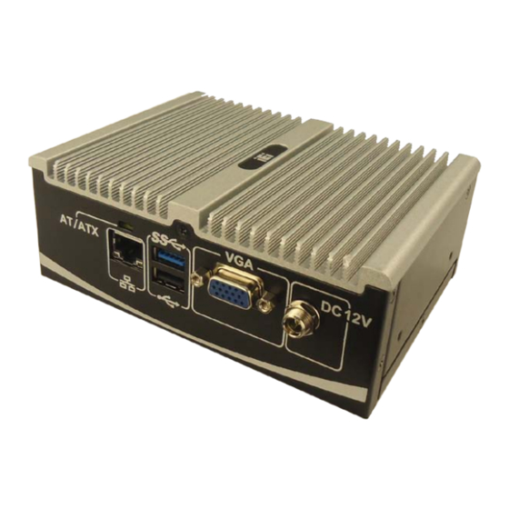
- Page 1 u IBX-230-BT Em b e d de d S ys te m MODEL: u IBX-230-BT S e rie s Fa n le s s Em b e d d e d S ys te m with In te l® Ce le ro n ® N2930 1.83 GHz, VGA , Gb E, On e US B 3.0, Th re e US B 2.0, On e COM a n d Ro HS Co m p lia n t Us e r Ma n u a l...
- Page 2 u IBX-230-BT Em b e d de d S ys te m Re vis io n Date Version Changes 11 November 2014 1.00 Initial release P a g e ii...
- Page 3 u IBX-230-BT Em b e d de d S ys te m Co p yrig h t COP YRIGHT NOTICE The information in this document is subject to change without prior notice in order to improve reliability, design and function and does not represent a commitment on the part of the manufacturer.
-
Page 4: Table Of Contents
u IBX-230-BT Em b e d de d S ys te m Ta b le o f Co n te n ts 1 INTRODUCTION ......................1 1.1 O ........................2 VERVIEW 1.2 M ....................2 ODEL ARIATIONS 1.3 F ........................3 EATURES 1.4 T .................. - Page 5 u IBX-230-BT Em b e d de d S ys te m 4 SYSTEM MOTHERBOARD ..................23 4.1 O ........................ 24 VERVIEW 4.1.1 Layout ......................24 4.2 I ..............24 NTERNAL ERIPHERAL ONNECTORS 4.2.1 AT/ATX Mode Select Switch ................25 4.2.2 Audio Connector ....................
- Page 6 u IBX-230-BT Em b e d de d S ys te m 5.2 M ........................47 5.3 A ....................... 48 DVANCED 5.3.1 ACPI Settings ....................49 5.3.2 IT8528 Super IO Configuration ............... 50 5.3.2.1 Serial Port 1 Configuration ............... 50 5.3.3 Hardware Monitor ...................
- Page 7 u IBX-230-BT Em b e d de d S ys te m Lis t o f Fig u re s Figure 1-1: uIBX-230-BT ......................... 2 Figure 1-2: uIBX-230-BT Front Panel .................... 5 Figure 1-3: uIBX-230-BT Rear Panel ..................... 5 Figure 1-4: Physical Dimensions (mm) ..................6 Figure 3-1: Retention Screws Removal ..................12 Figure 3-2: HDD Bracket ......................12 Figure 3-3: HDD Retention Screws .....................13...
- Page 8 u IBX-230-BT Em b e d de d S ys te m Figure 4-14: Power Button Connector Location ................36 Figure 4-15: Reset Button Connector Location .................37 Figure 4-16: RS-232 Serial Port Connector Location ..............38 Figure 4-17: SATA 3Gb/s Drive Connector Location ..............39 Figure 4-18: SATA Power Connector Location .................39 Figure 4-19: USB Connector Location ..................40 Figure 4-20: LAN Connector ......................41...
- Page 9 u IBX-230-BT Em b e d de d S ys te m Lis t o f Ta b le s Table 1-1: Model Variations ......................2 Table 1-2: Technical Specifications ....................4 Table 2-1: Package List Contents ....................9 Table 4-1: Peripheral Interface Connectors ................25 Table 4-2: AT/ATX Mode Select Switch Settings ...............26 Table 4-3: Audio Connector Pinouts ..................27 Table 4-4: Battery Connector Pinouts ..................28...
-
Page 10: Introduction
u IBX-230-BT Em b e d de d S ys te m Ch a p te r In tro d u c tio n P a g e 1... -
Page 11: Overview
SATA HDD with up to 3 Gb/s data transfer rate. One serial port, one USB 3.0 port and three USB 2.0 ports ensure simplified connectivity to a variety of external peripheral devices. 1.2 Mo d e l Va ria tio n s The model variations of the uIBX-230-BT series are listed below. Models Memory uIBX-230-BT-N2-R10 Intel®... -
Page 12: Features
u IBX-230-BT Em b e d de d S ys te m 1.3 Fe a tu re s The uIBX-230-BT features are listed below: Ultra compact size embedded system Intel® Celeron® processor N2930 1.83 GHz 7.5W on-board 1 x 2.5'' SATA 3Gb/s HDD/SSD drive bay ... -
Page 13: Front Panel
u IBX-230-BT Em b e d de d S ys te m 2560 x 1600 Re s o lu tio n 1 x Line-out, 1 x Mic-in Au d io P o we r DC Jack: 12 V DC P o we r In p u t 12 V@1.8 A (Intel®... -
Page 14: Rear Panel
u IBX-230-BT Em b e d de d S ys te m Figure 1-2: uIBX-230-BT Front Panel 1.6 Re a r P a n e l The rear panel of the uIBX-230-BT has the following features (Figure 1-3): 1 x AT/ATX Switch ... -
Page 15: Dimensions
u IBX-230-BT Em b e d de d S ys te m 1.7 Dim e n s io n s The physical dimensions are shown below: Figure 1-4: Physical Dimensions (mm) P a g e 6... -
Page 16: Unpacking
u IBX-230-BT Em b e d de d S ys te m Ch a p te r Un p a c kin g P a g e 7... -
Page 17: Anti - Static Precautions
u IBX-230-BT Em b e d de d S ys te m 2.1 An ti-s ta tic P re c a u tio n s WARNING: Failure to take ESD precautions during installation may result in permanent damage to the uIBX-230-BT and severe injury to the user. Electrostatic discharge (ESD) can cause serious damage to electronic components, including the uIBX-230-BT. -
Page 18: Packing List
u IBX-230-BT Em b e d de d S ys te m 2.3 P a c kin g Lis t NOTE: If some of the components listed in the checklist below are missing, please do not proceed with the installation. Contact the IEI reseller or vendor you purchased the uIBX-230-BT from or contact an IEI sales representative directly. -
Page 19: Installation
u IBX-230-BT Em b e d de d S ys te m Ch a p te r In s ta lla tio n P a g e 10... -
Page 20: Installation Precautions
u IBX-230-BT Em b e d de d S ys te m 3.1 In s ta lla tio n P re c a u tio n s During installation, be aware of the precautions below: Read the user manual: The user manual provides a complete description of the uIBX-230-BT, installation instructions and configuration options. -
Page 21: Figure 3-1: Retention Screws Removal
u IBX-230-BT Em b e d de d S ys te m Figure 3-1: Retention Screws Removal Open the HDD cover and locate the HDD bracket (Figure 3-2). S te p 2: Figure 3-2: HDD Bracket P a g e 12... -
Page 22: Figure 3-3: Hdd Retention Screws
u IBX-230-BT Em b e d de d S ys te m S te p 3: Attach the HDD to the HDD bracket, and then slide the HDD to connect the HDD to the SATA connector. (Figure 3-3). Figure 3-3: HDD Retention Screws S te p 4: Secure the HDD with the HDD bracket by four retention screws on the HDD cover. -
Page 23: At/Atx Mode Selection
u IBX-230-BT Em b e d de d S ys te m Figure 3-4: HDD Retention Screws S te p 5: Replace the HDD cover and secure it using three previously removed retention screws. 3.4 AT/ATX Mo d e S e le c tio n AT or ATX power mode can be used on the uIBX-230-BT. -
Page 24: At Power Mode
u IBX-230-BT Em b e d de d S ys te m Adjust the AT/ATX switch. S te p 2: S te p 0: 3.4.1 AT P owe r Mo d e With the AT mode selected, the power is controlled by a central power unit rather than a power switch. -
Page 25: Powering O N The System
u IBX-230-BT Em b e d de d S ys te m Figure 3-6: Reset Button Location S te p 2: Press the reset button. S te p 0: 3.6 P owe rin g On th e S ys te m To power on the system, follow the steps below: Press the power button on the front panel (Figure 3-7). -
Page 26: External Peripheral Interface Connectors
u IBX-230-BT Em b e d de d S ys te m S te p 4: Secure the brackets to the system by inserting two retention screws into each bracket as illustrated in Figure 3-8. Figure 3-8: Mounting Bracket Drill holes in the intended installation surface. S te p 5: S te p 6: Align the mounting holes in the sides of the mounting brackets with the predrilled... -
Page 27: Audio Connection
u IBX-230-BT Em b e d de d S ys te m 3.8.1 Au d io Co n n e c tio n The audio jacks on the external audio connector enable the uIBX-230-BT to be connected to a stereo sound setup. To install the audio devices, follow the steps below. S te p 1: Identify the audio plugs. -
Page 28: Lan Connection
u IBX-230-BT Em b e d de d S ys te m 3.8.2 LAN Co n n e c tio n There is one external RJ-45 LAN connector. The RJ-45 connector enables connection to an external network. To connect a LAN cable with an RJ-45 connector, please follow the instructions below. -
Page 29: Usb Device Connection
u IBX-230-BT Em b e d de d S ys te m Locate the DB-9 connector. The locations of the DB-9 connectors are shown S te p 1: in Chapter 1. S te p 2: Insert the serial connector. Insert the DB-9 connector of a serial device into the DB-9 connector on the uIBX-230-BT. -
Page 30: Vga Monitor Connection
u IBX-230-BT Em b e d de d S ys te m There are three USB 2.0 connectors and one USB 3.0 connector on the uIBX-230-BT. To connect a USB device, please follow the instructions below. S te p 1: Locate the USB connectors. -
Page 31: Figure 3-13: Vga Connector
u IBX-230-BT Em b e d de d S ys te m cable with the female DB-15 connector on the uIBX-230-BT. Insert the VGA connector. Once the connectors are properly aligned with the S te p 3: insert the male connector from the VGA screen into the female connector on the uIBX-230-BT. -
Page 32: System Motherboard
u IBX-230-BT Em b e d de d S ys te m Chapter S ys te m Mo th e rb o a rd P a g e 23... -
Page 33: Overview
u IBX-230-BT Em b e d de d S ys te m 4.1 Ove rvie w This chapter details all the jumpers and connectors of the system motherboard. 4.1.1 La yo u t The figures below show all the connectors and jumpers of the system motherboard. The Pin 1 locations of the on-board connectors are also indicated in the diagram below. -
Page 34: At/Atx Mode Select Switch
u IBX-230-BT Em b e d de d S ys te m Battery connector 2-pin wafer BAT1 BIOS FW connector 6-pin wafer JSPI1 Buzzer connector 2-pin wafer Clear CMOS button button J_CMOS1 CPU fan connector 4-pin wafer CPU_FAN1 DDR3L SO-DIMM slot DDR3L SO-DIMM slot DIMM1 Display port connector... -
Page 35: Audio Connector
u IBX-230-BT Em b e d de d S ys te m The AT/ATX mode select switch specifies the systems power mode as AT or ATX. AT/ATX mode select switch settings are shown in Table 4-2. Setting Description Short A-B AT Mode Short B-C ATX Mode... -
Page 36: Battery Connector
u IBX-230-BT Em b e d de d S ys te m Figure 4-3: Audio Connector Location Description Description LINE_OUTR LINEIN_R Analog_GND Analog_GND LINE_OUTL LINEIN_L Analog_GND Analog_GND LMIC1-R LMIC1-L Table 4-3: Audio Connector Pinouts 4.2.3 Ba tte ry Co n n e c to r CN La b e l: BAT1 CN Typ e :... -
Page 37: Bios Fw Connector
u IBX-230-BT Em b e d de d S ys te m Figure 4-4: Battery Connector Location Description Description VBATT Table 4-4: Battery Connector Pinouts 4.2.4 BIOS FW Co n n e c to r CN La b e l: J S P I1 6-pin wafer CN Typ e :... -
Page 38: Buzzer Connector
u IBX-230-BT Em b e d de d S ys te m Description Description +V1.8M_SPI_CON SPI_CS SPI_SO_SW SPI_CLK_SW SPI_SI_SW Table 4-5: BIOS FW Connector Pinouts 4.2.5 Bu zze r Co n n e c to r CN La b e l: CN Typ e : 2-pin wafer CN Lo c a tio n :... -
Page 39: Cpu Fan Connector
u IBX-230-BT Em b e d de d S ys te m CN Typ e : button CN Lo c a tio n : See Figure 3-6 See Table 4-7 CN S e ttin g s : If the uIBX-230-BT fails to boot due to improper BIOS settings, use the button to clear the CMOS data and reset the system BIOS information. -
Page 40: Ddr3L So-Dimm Slot
u IBX-230-BT Em b e d de d S ys te m Figure 4-8: CPU Fan Connector Location Description Description +V12_FAN FANIO1_EC FANOUT1_EC Table 4-8: CPU Fan Connector Pinouts 4.2.8 DDR3L S O-DIMM S lo t CN La b e l: DIMM1 DDR3L SO-DIMM slot CN Typ e :... -
Page 41: Display Port Connector
u IBX-230-BT Em b e d de d S ys te m Figure 4-9: DDR3L SO-DIMM Slot Location 4.2.9 Dis p la y P o rt Co n n e c to r CN La b e l: DP 1 20-pin box header CN Typ e : CN Lo c a tio n :... -
Page 42: Ec Fw Connector
u IBX-230-BT Em b e d de d S ys te m Description Description DDI1_HPD1# DPD_AUX_CTRL_P2 DPD_AUX_CTRL_N2 AUX_CTRL_DET_D DPD_OB_LANE2_P DPD_OB_LANE3_P DPD_OB_LANE2_N DPD_OB_LANE3_N DPD_OB_LANE0_P DPD_OB_LANE1_P DPD_OB_LANE0_N DPD_OB_LANE1_N Table 4-9: Display Port Connector Pinouts 4.2.10 EC FW Co n n e c to r CN La b e l: J P 3 2-pin header... -
Page 43: Front Panel Connector
u IBX-230-BT Em b e d de d S ys te m Description Description Table 4-10: EC FW Connector Pinouts 4.2.11 Fro n t P a n e l Co n n e c to r CN La b e l: 6-pin wafer CN Typ e : See Figure 4-12... -
Page 44: Power Button Connector
u IBX-230-BT Em b e d de d S ys te m CN Lo c a tio n : See Figure 4-13 CN P in o u ts : See Table 4-12 The LAN LED connectors connect to the LAN link LEDs on the system. Figure 4-13: LAN LED Connector Location Description Description... -
Page 45: Reset Button Connector
u IBX-230-BT Em b e d de d S ys te m Figure 4-14: Power Button Connector Location Description PWRBTN_SW# Table 4-13: Power Button Connector Pinouts 4.2.14 Re s e t Bu tto n Co n n e c to r CN La b e l: RS T_BTN1 CN Typ e :... -
Page 46: Rs-232 Serial Port Connector
u IBX-230-BT Em b e d de d S ys te m Figure 4-15: Reset Button Connector Location Description PM_SYSRST_R# Table 4-14: Reset Button Connector Pinouts 4.2.15 RS -232 S e ria l P o rt Co n n e c to r CN La b e l: COM1 CN Typ e :... -
Page 47: Sata 3Gb/S Drive Connector
u IBX-230-BT Em b e d de d S ys te m Figure 4-16: RS-232 Serial Port Connector Location Description Description -NDCD1 -NDSR1 NSIN1 -NRTS1 NSOUT1 -NCTS1 -NDTR1 -XRI1 Table 4-15: RS-232 Serial Port Connector Pinouts 4.2.16 S ATA 3Gb /s Drive Co n n e c to r CN La b e l: SATA1 CN Typ e :... -
Page 48: Sata Power Connector
u IBX-230-BT Em b e d de d S ys te m Figure 4-17: SATA 3Gb/s Drive Connector Location 4.2.17 S ATA P o we r Co n n e c to r CN La b e l: SATA_PWR1 2-pin wafer CN Typ e : CN Lo c a tio n : See Figure 4-18... -
Page 49: Usb Connector
u IBX-230-BT Em b e d de d S ys te m 4.2.18 US B Co n n e c to r CN La b e l: USB2_CAM1 CN Typ e : 8-pin header CN Lo c a tio n : See Figure 4-19 CN P in o u ts : See Table 4-17... -
Page 50: Lan Connector
u IBX-230-BT Em b e d de d S ys te m LAN connector RJ-45 LAN1 USB 2.0 & USB 3.0 connector USB 2.0 & USB 3.0 VGA Connector 15-pin female VGA1 Table 4-18: Rear Panel Connectors 4.3.1 LAN Co n n e c to r CN La b e l: LAN1 RJ-45... -
Page 51: Power Connector
u IBX-230-BT Em b e d de d S ys te m 4.3.2 P owe r Co n n e c to r CN La b e l: 12V DC IN CN Typ e : CN Lo c a tio n : See Figure 4-1 CN P in o u ts : See Table 4-21... -
Page 52: Vga Connector
u IBX-230-BT Em b e d de d S ys te m 4.3.1 VGA Co n n e c to r CN La b e l: VGA1 15-pin female (VGA) CN Typ e : CN Lo c a tio n : See Figure 4-1 CN P in o u ts : See Figure 4-21 and Table 4-23... -
Page 53: Bios
u IBX-230-BT Em b e d de d S ys te m Ch a p te r BIOS P a g e 44... -
Page 54: Introduction
u IBX-230-BT Em b e d de d S ys te m 5.1 In tro d u c tio n The BIOS is programmed onto the BIOS chip. The BIOS setup program allows changes to certain system settings. This chapter outlines the options that can be changed. NOTE: Some of the BIOS options may vary throughout the life cycle of the product and are subject to change without prior notice. -
Page 55: Getting Help
u IBX-230-BT Em b e d de d S ys te m Ke y Fu n c tio n Decrease the numeric value or make changes F1 key General help, only for Status Page Setup Menu and Option Page Setup Menu F2 key Load previous values. -
Page 56: Main
u IBX-230-BT Em b e d de d S ys te m The following sections completely describe the configuration options found in the menu items at the top of the BIOS screen and listed above. 5.2 Ma in The Main BIOS menu (BIOS Menu 1) appears when the BIOS Setup program is entered. The Main menu gives an overview of the basic system information. -
Page 57: Advanced
u IBX-230-BT Em b e d de d S ys te m S ys te m Da te [xx/xx/xx] Use the System Date option to set the system date. Manually enter the day, month and year. S ys te m Tim e [xx:xx:xx] Use the System Time option to set the system time. -
Page 58: Acpi Settings
u IBX-230-BT Em b e d de d S ys te m 5.3.1 ACP I S e ttin g s The ACPI Settings menu (BIOS Menu 3) configures the Advanced Configuration and Power Interface (ACPI) options. Aptio Setup Utility – Copyright (C) 2013 American Megatrends, Inc. Advanced ACPI Settings ACPI Sleep State... -
Page 59: It8528 Super Io Configuration
u IBX-230-BT Em b e d de d S ys te m 5.3.2 IT8528 S u p e r IO Co n fig u ra tio n Use the IT8528 Super IO Configuration menu (BIOS Menu 4) to set or change the configurations for the serial ports. -
Page 60: Hardware Monitor
u IBX-230-BT Em b e d de d S ys te m S e ria l P o rt [En a b le d ] Use the Serial Port option to enable or disable the serial port. Disable the serial port Disabled ... -
Page 61: Smart Fan Mode Configuration
u IBX-230-BT Em b e d de d S ys te m Aptio Setup Utility – Copyright (C) 2013 American Megatrends, Inc. Advanced PC Health Status Enable or Disable Smart > Smart Fan Function CPU temperature :+42 C CPU Fan Speed :N/A SOC_VCC :+0.774 V... - Page 62 u IBX-230-BT Em b e d de d S ys te m Aptio Setup Utility – Copyright (C) 2013 American Megatrends, Inc. Advanced Smart Fan Mode Configuration CPU Smart Fan control settings. CPU Smart Fan control [Auto PWM Mode] Temperature of Off Temperature of Start Start PWM ---------------------...
- Page 63 u IBX-230-BT Em b e d de d S ys te m the CPU is at a very high temperature and therefore cause the system to be damaged. The Temperature of Off option can only be set if the CPU Smart Fan control option is set to Auto Mode.
-
Page 64: Rtc Wake Settings
u IBX-230-BT Em b e d de d S ys te m Minimum Value: 0 Maximum Value: 100 S lo p e (Du ty Cyc le ) [4] The Slope (Duty Cycle) option can only be set if the CPU Smart Fan control option is set to Auto Mode. -
Page 65: Serial Port Console Redirection
u IBX-230-BT Em b e d de d S ys te m Wa ke s ys te m with Fixe d Tim e [Dis a b le d ] Use the Wake system with Fixed Time option to enable or disable the system wake on alarm event. -
Page 66: Console Redirection Settings
u IBX-230-BT Em b e d de d S ys te m Aptio Setup Utility – Copyright (C) 2013 American Megatrends, Inc. Advanced COM1 Console Redirection Console Redirection [Disabled] Enable or Disable > Console Redirection Settings --------------------- : Select Screen ↑... - Page 67 u IBX-230-BT Em b e d de d S ys te m Aptio Setup Utility – Copyright (C) 2013 American Megatrends, Inc. Advanced COM1 Emulation: ANSI: Console Redirection Settings Extended ASCII char set. VT100: ASCII char set. Terminal Type [ANSI] VT100+: Extends VT100 to Bits per second [115200]...
- Page 68 u IBX-230-BT Em b e d de d S ys te m Sets the serial port transmission speed at 38400. 38400 57600 Sets the serial port transmission speed at 57600. 115200 Sets the serial port transmission speed at 115200. EFAULT ...
-
Page 69: Cpu Configuration
u IBX-230-BT Em b e d de d S ys te m 5.3.6 CP U Co n fig u ra tio n Use the CPU Configuration menu (BIOS Menu 5) to view detailed CPU specifications and configure the CPU. Aptio Setup Utility – Copyright (C) 2013 American Megatrends, Inc. Advanced CPU Configuration When enabled, a VMM can... -
Page 70: Ide Configuration
u IBX-230-BT Em b e d de d S ys te m Disables the Intel Speed Step Technology. Disabled Enabled Enables the Intel Speed Step Technology. EFAULT 5.3.7 IDE Co n fig u ra tio n Use the IDE Configuration menu (BIOS Menu 12) to change and/or set the configuration of the SATA devices installed in the system. -
Page 71: Usb Configuration
u IBX-230-BT Em b e d de d S ys te m S ATA P o rt 0 Ho tP lu g [Dis a b le d ] Use the Serial-ATA Port 0 HotPlug option to enable or disable the SATA device hot plug. ... -
Page 72: Chipset
u IBX-230-BT Em b e d de d S ys te m does not become available until a USB compatible operating system is fully booted with all USB drivers loaded. When this option is enabled, any attached USB mouse or USB keyboard can control the system even when there is no USB driver loaded onto the system. -
Page 73: North Bridge Configuration
u IBX-230-BT Em b e d de d S ys te m 5.4.1 No rth Brid g e Co n fig u ra tio n Use the North Bridge Configuration menu (BIOS Menu 15) to configure the Intel IGD settings. Aptio Setup Utility –... - Page 74 u IBX-230-BT Em b e d de d S ys te m Aptio Setup Utility – Copyright (C) 2013 American Megatrends, Inc. Chipset DVMT Pre-Allocated [256M] Select DVMT 5.0 DVMT Total Gfx Mem [Max] Pre-Allocated (Fixed) Graphics Memory size Primary IGFX Boot Display [VBIOS Default] used by the Internal Graphics Device.
-
Page 75: Southbridge Configuration
u IBX-230-BT Em b e d de d S ys te m P rim a ry IGFX Bo o t Dis p la y [VBIOS De fa u lt] Use the Primary IGFX Boot Display option to select the display device used by the system when it boots. - Page 76 u IBX-230-BT Em b e d de d S ys te m The system turns on Power On Last State The system returns to its previous state. If it was on, it EFAULT turns itself on. If it was off, it remains off. ...
-
Page 77: Security
u IBX-230-BT Em b e d de d S ys te m 5.5 S e c u rity Use the Security menu (BIOS Menu 18) to set system and user passwords. Aptio Setup Utility – Copyright (C) 2013 American Megatrends, Inc. Main Advanced Chipset... -
Page 78: Boot
u IBX-230-BT Em b e d de d S ys te m 5.6 Bo o t Use the Boot menu (BIOS Menu 19) to configure system boot options. Aptio Setup Utility – Copyright (C) 2013 American Megatrends, Inc. Main Advanced Chipset Security Boot... - Page 79 u IBX-230-BT Em b e d de d S ys te m Qu ie t Bo o t [En a b le d ] Use the Quiet Boot BIOS option to select the screen display when the system boots. ...
-
Page 80: Exit
u IBX-230-BT Em b e d de d S ys te m 5.7 Exit Use the Exit menu (BIOS Menu 20) to load default BIOS values, optimal failsafe values and to save configuration changes. Aptio Setup Utility – Copyright (C) 2013 American Megatrends, Inc. Main Advanced Chipset... - Page 81 u IBX-230-BT Em b e d de d S ys te m S a ve a s Us e r De fa u lts Use the Save as User Defaults option to save the changes done so far as user defaults. ...
-
Page 82: A Safety Precautions
u IBX-230-BT Em b e d de d S ys te m Appendix S a fe ty P re c a u tio n s P a g e 73... -
Page 83: Safety Precautions
u IBX-230-BT Em b e d de d S ys te m A.1 S a fe ty P re c a u tio n s WARNING: The precautions outlined in this appendix should be strictly followed. Failure to follow these precautions may result in permanent damage to the uIBX-230-BT. -
Page 84: Product Disposal
u IBX-230-BT Em b e d de d S ys te m Electrostatic discharge (ESD) can cause serious damage to electronic components, including the uIBX-230-BT. Dry climates are especially susceptible to ESD. It is therefore critical that whenever the uIBX-230-BT is opened and any of the electrical components are handled, the following anti-static precautions are strictly adhered to. -
Page 85: Maintenance And Cleaning Precautions
u IBX-230-BT Em b e d de d S ys te m monitors and electrical accessories, such as signal cables or power cords. When you need to dispose of your display products, please follow the guidance of your local authority, or ask the shop where you purchased the product. - Page 86 u IBX-230-BT Em b e d de d S ys te m Vacuum cleaner – Using a vacuum specifically designed for computers is one of the best methods of cleaning the uIBX-230-BT. Dust and dirt can restrict the airflow in the uIBX-230-BT and cause its circuitry to corrode. ...
-
Page 87: B Bios Menu Options
u IBX-230-BT Em b e d de d S ys te m Appendix BIOS Me n u Op tio n s P a g e 78... - Page 88 u IBX-230-BT Em b e d de d S ys te m System Date [xx/xx/xx] ......................48 System Time [xx:xx:xx] .......................48 ACPI Sleep State [S3 only (Suspend to RAM)] ..............49 Serial Port [Enabled] ......................51 Change Settings [Auto] .......................51 ...
- Page 89 u IBX-230-BT Em b e d de d S ys te m Bootup NumLock State [On] ....................69 Quiet Boot [Enabled] ......................70 Option ROM Messages [Force BIOS] .................70 UEFI Boot [Disabled] ......................70 Launch PXE OpROM [Disabled] ..................70 ...
-
Page 90: C Watchdog Timer
u IBX-230-BT Em b e d de d S ys te m Appendix Wa tc h d o g Tim e r P a g e 81... - Page 91 u IBX-230-BT Em b e d de d S ys te m NOTE: The following discussion applies to DOS environment. IEI support is contacted or the IEI website visited for specific drivers for more sophisticated operating systems, e.g., Windows and Linux. The Watchdog Timer is provided to ensure that standalone systems can always recover from catastrophic conditions that cause the CPU to crash.
- Page 92 u IBX-230-BT Em b e d de d S ys te m NOTE: When exiting a program it is necessary to disable the Watchdog Timer, otherwise the system resets. Example program: ; INITIAL TIMER PERIOD COUNTER W_LOOP: AX, 6F02H ;setting the time-out value BL, 05 ;time-out value is 5 seconds ;...
-
Page 93: D Hazardous Materials Disclosure
u IBX-230-BT Em b e d de d S ys te m Ap p e n d ix Ha za rd o u s Ma te ria ls Dis c lo s u re P a g e 84... -
Page 94: Hazardous Materials Disclosure Table For Ipb Products Certified As R Ohs Compliant Under 2002/95/Ec Without Mercury
u IBX-230-BT Em b e d de d S ys te m D.1 Ha za rd o u s Ma te ria ls Dis c lo s u re Ta ble for IP B P ro d u c ts Ce rtifie d a s Ro HS Co m p lia n t Un d e r 2002/95/EC With o u t Me rc u ry The details provided in this appendix are to ensure that the product is compliant with the... - Page 95 u IBX-230-BT Em b e d de d S ys te m P a rt Na m e To xic o r Ha za rd o u s S u b s ta n c e s a n d Ele m e n ts Le a d Me rc u ry Ca d m iu m...
- Page 96 u IBX-230-BT Em b e d de d S ys te m 此附件旨在确保本产品符合中国 RoHS 标准。以下表格标示此产品中某有毒物质的含量符 合中国 RoHS 标准规定的限量要求。 本产品上会附有”环境友好使用期限”的标签,此期限是估算这些物质”不会有泄漏或突变”的 年限。本 产品可能包含有较短的环境友好使用期限的可替换元件,像是 电池或灯管,这些元 件将会单独标示出来。 部件名称 有毒有害物质或元素 铅 汞 镉 六价铬 多溴联苯 多溴二苯 醚 (P b ) (Hg ) (Cd ) (CR(VI)) (P BB) (P BDE) 壳体...
Need help?
Do you have a question about the uIBX-230-BT Series and is the answer not in the manual?
Questions and answers