Table of Contents
Advertisement
Quick Links
Advertisement
Table of Contents

Related Manuals for IEI Technology TANK-871-Q170i Series


Summary of Contents for IEI Technology TANK-871-Q170i Series
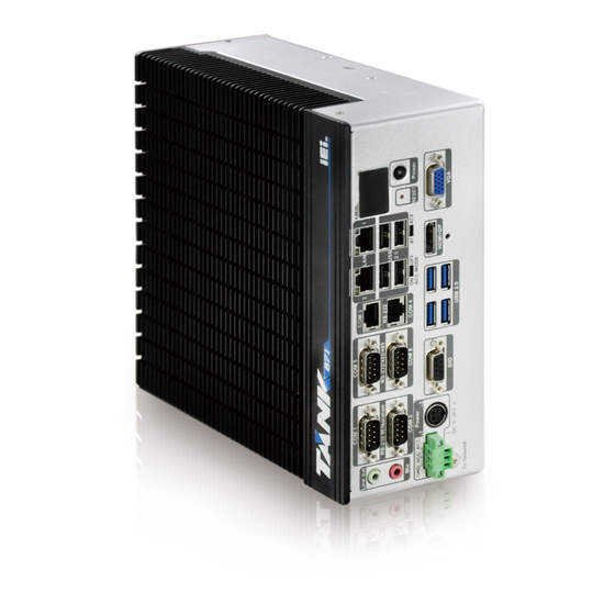
- Page 1 TANK-871-Q170i Embedded System MODEL: TANK-871-Q170i Series Embedded System with 6th Generation Intel® Core™ processor, 4GB DDR4 pre-installed memory, VGA/HDMI+DP/iDP, Two Gigabit Ethernet, RS-232/422/485, RoHS Compliant User Manual Page I Rev. 1.02 – 8 May 2019...
- Page 2 TANK-871-Q170i Embedded System Revision Date Version Changes 8 May 2019 1.02 Update Section 2.3: Unpacking Checklist 14 May 2018 1.01 Update the pin define in the followings: Section 4.3.3: Ethernet and USB 2.0 Connectors (LAN1_USB1) Section 4.3.4: Ethernet and USB 2.0 Connectors (LAN2_USB2) Section 4.3.10: USB 3.0 Connectors (USB3_CN1) Section 4.3.11: USB 3.0 Connectors (USB3_CN2)
- Page 3 TANK-871-Q170i Embedded System Copyright COPYRIGHT NOTICE The information in this document is subject to change without prior notice in order to improve reliability, design and function and does not represent a commitment on the part of the manufacturer. In no event will the manufacturer be liable for direct, indirect, special, incidental, or consequential damages arising out of the use or inability to use the product or documentation, even if advised of the possibility of such damages.
- Page 4 TANK-871-Q170i Embedded System Manual Conventions WARNING Warnings appear where overlooked details may cause damage to the equipment or result in personal injury. Warnings should be taken seriously. CAUTION Cautionary messages should be heeded to help reduce the chance of losing data or damaging the product. NOTE These messages inform the reader of essential but non-critical information.
-
Page 5: Table Of Contents
TANK-871-Q170i Embedded System Table of Contents 1 INTRODUCTION ......................1 1.1 O ........................2 VERVIEW 1.2 M ....................3 ODEL ARIATIONS 1.3 F ........................3 EATURES 1.4 T ..................4 ECHNICAL PECIFICATIONS 1.5 F ......................6 RONT ANEL 1.6 R ....................... - Page 6 TANK-871-Q170i Embedded System 3.5.10 DB-9 RS-232/422/485 Serial Port Connectors ..........27 3.5.11 USB Connectors ..................... 28 3.5.12 VGA Connector ....................29 3.6 P ................30 OWERING FF THE YSTEM 3.7 P ........................31 OWER 3.7.1 ACC ON Mode ....................32 3.7.2 ACC OFF Mode ....................
- Page 7 TANK-871-Q170i Embedded System 4.3.10 USB 3.0 Connectors (USB3_CN1) ..............44 4.3.11 USB 3.0 Connectors (USB3_CN2) ..............44 4.3.12 VGA Connector (VGA1) ................. 45 5 BIOS ..........................46 5.1 I ......................47 NTRODUCTION 5.1.1 Starting Setup ....................47 5.1.2 Using Setup ...................... 47 5.1.3 Getting Help .....................
- Page 8 TANK-871-Q170i Embedded System 5.4.2.2 HD Audio Configuration ................83 5.5 S ......................... 84 ECURITY 5.6 B ........................85 5.7 S & E ......................87 5.8 S ......................88 ERVER 5.8.1.1 System Event Log ..................89 5.8.1.2 BMC network configuration ..............90 A REGULATORY COMPLIANCE ................
- Page 9 TANK-871-Q170i Embedded System List of Figures Figure 1-1: TANK-871-Q170i series ....................2 Figure 1-2: TANK-871-Q170i series Front Panel ................6 Figure 1-3: TANK-871-Q170i series Rear Panel ................7 Figure 1-4: TANK-871-Q170i series LED Indicators ..............8 Figure 1-5: Physical Dimensions (millimeters) ................9 Figure 3-1: Bottom Panel Retention Screws ................
- Page 10 TANK-871-Q170i Embedded System Figure 4-1: System Motherboard (Front) ..................35 Figure 4-2: System Motherboard (Rear) ..................35 Page X...
- Page 11 TANK-871-Q170i Embedded System List of Tables Table 1-1: TANK-871-Q170i series Model Variations ..............3 Table 1-2: Technical Specifications ....................5 Table 1-3: LED Indicators Description..................8 Table 3-1: RJ-45 Ethernet Connector LEDs ................24 Table 3-2: Power LED Indicators Description ................31 Table 4-1: Peripheral Interface Connectors ................
- Page 12 TANK-871-Q170i Embedded System Table 4-26: USB 3.0 Connectors Pinouts (USB3_CN1) ............. 44 Table 4-27: USB 3.0 Connectors Pinouts (USB3_CN2) ............. 44 Table 4-28: VGA Connector Pinouts (VGA1) ................45 Table 5-1: BIOS Navigation Keys ....................48 Page XII...
- Page 13 TANK-871-Q170i Embedded System BIOS Menus BIOS Menu 1: Main ........................50 BIOS Menu 2: Advanced ......................52 BIOS Menu 3: CPU Configuration ....................53 BIOS Menu 4: Trusted Computing ....................55 BIOS Menu 5: ACPI Configuration ....................56 BIOS Menu 6: SATA Configuration ..................... 57 BIOS Menu 7: AMT Configuration ....................
- Page 14 TANK-871-Q170i Embedded System BIOS Menu 31: PCH Azalia Configuration Menu ............... 90 Page XIV...
-
Page 15: Introduction
TANK-871-Q170i Embedded System Chapter Introduction Page 1... -
Page 16: Overview
Intel® Q170 chipset and supports two 260-pin DDR4 SDRAM SO-DIMM modules up to 64 GB (4GB memory preinstalled). The TANK-871-Q170i series includes one VGA port, one HDMI+DP port, one iDP port (optional), two GbE LAN ports, four USB 3.0 ports, four USB 2.0 ports, four RS-232 connectors and two RS-232/422/485 connectors. -
Page 17: Model Variations
TANK-871-Q170i Embedded System 1.2 Model Variations The model variations of the TANK-871-Q170i series are listed below. Model No. TANK-871-Q170i-i7/4G-R10 Intel® Core i7-6700TE 2.4GHz, (up to 3.4 GHz, Quad Core, TDP 35W) TANK-871-Q170i-i5/4G-R10 Intel® Core i5-6500TE 2.3GHz, (up to 3.3 GHz, Quad Core, TDP 35W) TANK-871-Q170i-i3/4G-R10 Intel®... -
Page 18: Technical Specifications
TANK-871-Q170i Embedded System 1.4 Technical Specifications The TANK-871-Q170i series technical specifications are listed in Table 1-2. Specifications Chassis Black C + Silver Color Dimensions (WxHxD) (mm) 82.2 x 255.2 x 204 System Fan Fanless Chassis Construction Extruded aluminum alloy Motherboard Intel®... -
Page 19: Table 1-2: Technical Specifications
TANK-871-Q170i Embedded System Specifications 8 bit Digital I/O, 4 bit input / 4 bit output Digital I/O 1 x VGA 1 x HDMI+DP Display 1 x iDP (optional) VGA: Up to 1920 x 1200@60Hz Resolution HDMI: Up to 4096×2160@24Hz Audio 1 x Line-out, 1 x Mic-in Wireless 1 x 802.11 a/b/g/n/ac (optional) -
Page 20: Front Panel
TANK-871-Q170i Embedded System 1.5 Front Panel The front panel of the TANK-871-Q170i series has the following features (Figure 1-2): Figure 1-2: TANK-871-Q170i series Front Panel Connectors and buttons on the front panel include the following: 1 x 4-pin power DC jack for 9 V ~ 36 V power input ... -
Page 21: Rear Panel
The rear panel of the TANK-871-Q170i series has the following features (Figure 1-2): Figure 1-3: TANK-871-Q170i series Rear Panel 1.7 LED Indicators There are several indicators on the rear panel of the TANK-871-Q170i series as shown in Figure 1-4. Page 7... -
Page 22: Figure 1-4: Tank-871-Q170I Series Led Indicators
TANK-871-Q170i Embedded System Figure 1-4: TANK-871-Q170i series LED Indicators The descriptions of each LED indicator are listed below. LED Indicator Description AT Power Mode The current power mode status is AT mode. Controlled by the AT/ATX power mode switch. Shows IPMI status. -
Page 23: Physical Dimensions
TANK-871-Q170i Embedded System 1.8 Physical Dimensions The physical dimensions of the TANK-870-Q170-2 slot are shown in Figure 1-5. Figure 1-5: Physical Dimensions (millimeters) Page 9... -
Page 24: Unpacking
TANK-871-Q170i Embedded System Chapter Unpacking Page 10... -
Page 25: Anti-Static Precautions
Electrostatic discharge (ESD) can cause serious damage to electronic components, including the TANK-871-Q170i series. Dry climates are especially susceptible to ESD. It is therefore critical that whenever the TANK-871-Q170i series or any other electrical component is handled, the following anti-static precautions are strictly adhered to. -
Page 26: Unpacking Checklist
If some of the components listed in the checklist below are missing, please do not proceed with the installation. Contact the IEI reseller or vendor you purchased the TANK-871-Q170i series from or contact an IEI sales representative directly. To contact an IEI sales representative, please send an email to sales@ieiworld.com. - Page 27 TANK-871-Q170i Embedded System Optional European power cord (P/N: 32702-000400-200-RS) Power adapter, FSP120-ABBN2, 9NA1205302, Active PFC, Vin:90~264VAC, 120W, plug=6.5mm, cable=1500mm, Erp (no load 0.15W), Vout:19VDC, 4-pin DIN with lock, CCL, RoHS (P/N: 63040-010120-210-RS) IPMI 2.0 adapter card with AST2400 BMC chip for DDR3 SO-DIMM socket interface (P/N: iRIS-2400-R10) 1T1R wifi module kit for embedded system,...
-
Page 28: Installation
TANK-871-Q170i Embedded System Chapter Installation Page 14... -
Page 29: Installation Precautions
Electric shock and personal injury might occur if the rear panel of the TANK-871-Q170i series is opened while the power cord is still connected to an electrical outlet. -
Page 30: Hard Disk Drive (Hdd) Installation
TANK-871-Q170i Embedded System 3.2 Hard Disk Drive (HDD) Installation To install the hard drive, please follow the steps below: Step 1: Remove the bottom panel by removing the eight retention screws from the bottom panel. Figure 3-1: Bottom Panel Retention Screws Step 2: Remove the four HDD bracket retention screws and then lift the HDD bracket out of the system. -
Page 31: Figure 3-2: Hdd Bracket Retention Screws
TANK-871-Q170i Embedded System Figure 3-2: HDD Bracket Retention Screws Step 3: Attach each HDD to the HDD bracket, and then slide each HDD to connect the SATA connectors. Figure 3-3: HDD Installation Page 17... -
Page 32: Memory Module Replacement
Reinstall the bottom panel to the TANK-871-Q170i series. 3.3 Memory Module Replacement The TANK-871-Q170i series support two 260-pin DDR4 SDRAM SO-DIMM modules up to 64 GB (4GB memory preinstalled). If the memory module fails, follow the instructions below to replace the memory module. -
Page 33: Mounting The System With Mounting Brackets
DDR4 memory module in the socket. Figure 3-5: DDR4 SO-DIMM Module Installation Step 8: Reinstall the bottom panel to the TANK-871-Q170i series. CAUTION: For dual channel configuration, always install two identical memory modules that feature the same capacity, timings, voltage, number of ranks and the same brand. -
Page 34: External Peripheral Interface Connectors
Insert four retention screws, two in each bracket, to secure the system to the wall. 3.5 External Peripheral Interface Connectors The TANK-871-Q170i series has the following connectors. Detailed descriptions of the connectors can be found in the subsections below. ... -
Page 35: Acc Mode Selection
3.5.1 ACC Mode Selection The ACC mode is designed for vehicle applications. The TANK-871-Q170i series allows turning the ACC mode on or off. The setting can be made through the ACC mode switch on the external peripheral interface panel as shown below. -
Page 36: At/Atx Power Mode Selection
TANK-871-Q170i Embedded System 3.5.2 AT/ATX Power Mode Selection The TANK-871-Q170i series supports AT and ATX power modes. The setting can be made through the AT/ATX power mode switch on the external peripheral interface panel as shown below. Figure 3-8: AT/ATX Power Mode Switch 3.5.3 Audio Connector... -
Page 37: Digital Input/Output Connector
Locate the RJ-45 connectors. The locations of the RJ-45 connectors are shown in Figure 1-2. Step 2: Align the connectors. Align the RJ-45 connector on the LAN cable with one of the RJ-45 connectors on the TANK-871-Q170i series. See Figure 3-11. Figure 3-11: LAN Connection Page 23... -
Page 38: Power Input, 3-Pin Terminal Block
TANK-871-Q170i Embedded System Step 3: Insert the LAN cable RJ-45 connector. Once aligned, gently insert the LAN cable RJ-45 connector into the on-board RJ-45 connector. Figure 3-12: RJ-45 Ethernet Connector The RJ-45 Ethernet connector has two status LEDs, one green and one yellow. The green LED indicates activity on the port and the yellow LED indicates the port is linked. -
Page 39: Power Input, 4-Pin Din Connector
TANK-871-Q170i Embedded System 3.5.7 Power Input, 4-pin DIN Connector The power connector connects to the 9 V~36 V DC power adapter. Figure 3-14: Power Input Connector 3.5.8 DB-9 RS-232 Serial Port Connectors DB-9 RS-232 serial port devices can be attached to the DB-9 ports on the rear panel. Step 1: Locate the DB-9 connector. -
Page 40: Rs-232 Serial Ports
TANK-871-Q170i Embedded System Figure 3-16: DB-9 RS-232 Serial Port Connector 3.5.9 RJ-45 RS-232 Serial Ports RS-232 serial port devices can be attached to the RJ-45 RS-232 serial ports on the rear panel. Step 1: Locate the RJ-45 RS-232 connectors. The locations of the RJ-45 RS-232 connectors are shown in Figure 1-2. -
Page 41: Rs-232/422/485 Serial Port Connectors
TANK-871-Q170i Embedded System Step 3: Insert the serial connector. Insert the DB-9 connector of a serial device into the DB-9 connector on the RJ-45 to DB-9 COM port cable. Step 4: Secure the connector. Secure the serial device connector to the external interface by tightening the two retention screws on either side of the connector. -
Page 42: Usb Connectors
TANK-871-Q170i Embedded System Step 3: Secure the connector. Secure the serial device connector to the external interface by tightening the two retention screws on either side of the connector. Figure 3-20: DB-9 RS-232/422/485 Serial Port Connector 3.5.11 USB Connectors The USB ports are for connecting USB peripheral devices to the system. Step 1: Locate the USB connectors. -
Page 43: Vga Connector
Once the connectors are properly aligned with, insert the male connector from the VGA screen into the female connector on the TANK-871-Q170i series. See Figure 3-22. Figure 3-22: VGA Connector Step 4: Secure the connector. Secure the DB-15 VGA connector from the VGA monitor to the external interface by tightening the two retention screws on either side of the connector. -
Page 44: Powering On/Off The System
TANK-871-Q170i Embedded System Figure 3-23: VGA Connector 3.6 Powering On/Off the System WARNING: Make sure a power supply with the correct input voltage is being fed into the system. Incorrect voltages applied to the system may cause damage to the internal electronic components and may also cause injury to the user. ... -
Page 45: Power
TANK-871-Q170i Embedded System 3.7 Power There are two power connectors on the rear panel. Power 1 connector is a 3-pin terminal block that supports ACC On signal. Power 2 connector is a DIN connector that can directly connect to a power adapter. The supported power input voltages are: ... -
Page 46: Acc On Mode
TANK-871-Q170i Embedded System 3.7.1 ACC ON Mode 1. The TANK-871-Q170i series supports single power input and also can be simultaneously connected to two power sources. When both power connectors are connected to power sources with 9 V~36 V power input, the one with higher voltage will supply power to the system. - Page 47 TANK-871-Q170i Embedded System Step 2: Make sure at least one DDR4 DIMM is installed in one of the DIMM sockets. If multiple DIMMs are installed, all of the DIMMs must be same size, same speed and same brand to get the best performance. Step 3: Connect an Ethernet cable to the RJ-45 connector labeled LAN1 (Figure 1-2).
-
Page 48: System Motherboard
TANK-871-Q170i Embedded System Chapter System Motherboard Page 34... -
Page 49: Overview
TANK-871-Q170i Embedded System 4.1 Overview This chapter details all the jumpers and connectors of the system motherboard. 4.1.1 Layout The figures below show all the connectors and jumpers of the system motherboard. The Pin 1 locations of the on-board connectors are also indicated in the diagram below. Figure 4-1: System Motherboard (Front) Figure 4-2: System Motherboard (Rear) Page 35... -
Page 50: Internal Peripheral Connectors
TANK-871-Q170i Embedded System 4.2 Internal Peripheral Connectors The table below shows a list of the internal peripheral interface connectors on the system motherboard. Pinouts of these connectors can be found in the following sections. Connector Type Label Backplane power connector 4-pin wafer Battery connector 2-pin wafer... -
Page 51: Battery Connector (Bat1)
TANK-871-Q170i Embedded System 4.2.2 Battery Connector (BAT1) PIN NO. DESCRIPTION VBATT Table 4-3: Battery Connector Pinouts (BAT1) 4.2.3 BIOS Programming Connector (JSPI1) PIN NO. DESCRIPTION PIN NO. DESCRIPTION +V3.3M_SPI_CON SPI_CS SPI_SO_SW SPI_CLK_SW SPI_SI_SW Table 4-4: BIOS Programming Connector Pinouts (JSPI1) 4.2.4 CPU Fan Connector (CPU_FAN1) PIN NO. -
Page 52: Ec Debug Connector (Cn4)
TANK-871-Q170i Embedded System DPD_OB_LANE1_N_C VCC3 Table 4-6: DisplayPort connector Pinouts (DP1) 4.2.6 EC Debug Connector (CN4) PIN NO. DESCRIPTION PIN NO. DESCRIPTION KSI0 KSO9 KSO0 KSO10 KSO1 KSO12 KSO2 KSI1 KSO3 KSO11 KSO4 KSI2 KSO5 KSI3 KSO6 KSO7 KSO8 Table 4-7: EC Debug Connector Pinouts (CN4) 4.2.7 EC Programming Connector (JSPI2) PIN NO. -
Page 53: Led Connector (J2)
TANK-871-Q170i Embedded System 4.2.9 LED Connector (J2) PIN NO. DESCRIPTION PIN NO. DESCRIPTION +V3.3S_IO +V3.3A_EC_IO IRST_PD# IATX_LED# IPWRLED01# IPWRLED02# IIPMI_LED# ICPU_LED# IDISKLED# Table 4-10: LED Connector Pinouts (J2) 4.2.10 SATA Power Connectors (CN2, CN3) PIN NO. DESCRIPTION +V5S Table 4-11: SATA Power Connectors Pinouts (CN2, CN3) 4.2.11 TPM Connector (TPM1) PIN NO. -
Page 54: Usb 3.0 Connectors (Usb3-1)
TANK-871-Q170i Embedded System 4.2.12 USB 3.0 connectors (USB3-1) PIN NO. DESCRIPTION PIN NO. DESCRIPTION VCC_USB3_56 USB3_RX5_N_C USB3_RX5_P_C USB3P1_TXDN5_C USB3P1_TXDP5_C USB2P5_DM1_L USB2P5_DP1_L USB2P6_DP2_L USB2P6_DM2_L USB3P1_TXDP6_C USB3P1_TXDN6_C USB3_RX6_P_C USB3_RX6_N_C VCC_USB3_56 Table 4-13: USB 3.0 connectors Pinouts (USB3-1) 4.3 External Interface Panel Connectors The table below shows a list of the external interface panel connectors on the system motherboard. -
Page 55: Audio Jack (Jaudio1)
TANK-871-Q170i Embedded System 4.3.1 Audio Jack (JAUDIO1) PIN NO. DESCRIPTION PIN NO. DESCRIPTION ILMIC1-CONN-L IJD_MIC ILMIC1-CONN-R ILFRONT-L IJD_FRONT ILFRONT-R Table 4-15: Audio Jack Pinouts (JAUDIO1) 4.3.2 DIO connector (DIO1) PIN NO. DESCRIPTION PIN NO. DESCRIPTION DIN0 DOUT0 DIN1 DOUT1 DIN2 DOUT2 DIN3 DOUT3... -
Page 56: Ethernet And Usb 2.0 Connectors (Lan2_Usb2)
TANK-871-Q170i Embedded System DESCRIPTION DESCRIPTION ILAN_MDI3_DN ILAN1_1000- ILAN1_100- ILAN1_LINK_ACT- ILAN1_LINK_PWR Table 4-18: LAN Pinouts (LAN1) 4.3.4 Ethernet and USB 2.0 Connectors (LAN2_USB2) DESCRIPTION DESCRIPTION USBV9L DATA9_N DATA9_P IO_GND USBV9L DATA10_N DATA10_P IO_GND Table 4-19: USB 2.0 Port Pinouts (USB2) DESCRIPTION DESCRIPTION ITRD2P0 ITRD2N0... -
Page 57: Power Connector (Pwr2)
TANK-871-Q170i Embedded System 4.3.6 Power Connector (PWR2) PIN NO. DESCRIPTION PIN NO. DESCRIPTION ACCON +VIN Table 4-22: Power Connector Pinouts (PWR1) 4.3.7 RS-232 Serial Port Connector (COM1_2) PIN NO. DESCRIPTION PIN NO. DESCRIPTION 1(10) 6(15) 2(11) 7(16) 3(12) 8(17) 4(13) 9(18) 5(14) Table 4-23: RS-232 Serial Port Connector Pinouts (COM1_2) -
Page 58: Usb 3.0 Connectors (Usb3_Cn1)
TANK-871-Q170i Embedded System 7(16) 8(17) 9(18) Table 4-25: RS-232/422/485 Serial Port Connector Pinout (COM5_6) 4.3.10 USB 3.0 Connectors (USB3_CN1) PIN NO. DESCRIPTION PIN NO. DESCRIPTION VCC_USB12 USB_PN1_C USB_PP1_C USB3_RX1_N_C USB3_RX1_P_C USB3_TX1_N_C USB3_TX1_P_C VCC_USB12 USB_PN2_C USB_PP2_C USB3_RX2_N_C USB3_RX2_P_C USB3_TX2_N_C USB3_TX2_P_C Table 4-26: USB 3.0 Connectors Pinouts (USB3_CN1) 4.3.11 USB 3.0 Connectors (USB3_CN2) PIN NO. -
Page 59: Vga Connector (Vga1)
TANK-871-Q170i Embedded System 4.3.12 VGA Connector (VGA1) PIN NO. DESCRIPTION PIN NO. DESCRIPTION Green Blue VGAVCC HOTPLUG DDCDAT HSYNC VSYNC DDCCLK Table 4-28: VGA Connector Pinouts (VGA1) Page 45... -
Page 60: Bios
TANK-871-Q170i Embedded System Chapter BIOS Page 46... -
Page 61: Introduction
TANK-871-Q170i Embedded System 5.1 Introduction The BIOS is programmed onto the BIOS chip. The BIOS setup program allows changes to certain system settings. This chapter outlines the options that can be changed. NOTE: Some of the BIOS options may vary throughout the life cycle of the product and are subject to change without prior notice. -
Page 62: Getting Help
TANK-871-Q170i Embedded System Function Decrease the numeric value or make changes Page Up key Increase the numeric value or make changes Page Dn key Decrease the numeric value or make changes Esc key Main Menu – Quit and not save changes into CMOS Status Page Setup Menu and Option Page Setup Menu -- Exit current page and return to Main Menu General help, only for Status Page Setup Menu and Option... - Page 63 TANK-871-Q170i Embedded System Save & Exit – Selects exit options and loads default settings. The following sections completely describe the configuration options found in the menu items at the top of the BIOS screen and listed above. Page 49...
-
Page 64: Main
TANK-871-Q170i Embedded System 5.2 Main The Main BIOS menu (BIOS Menu 1) appears when the BIOS Setup program is entered. The Main menu gives an overview of the basic system information. Aptio Setup Utility – Copyright (C) 2017 American Megatrends, Inc. Main Advanced Chipset... -
Page 65: Advanced
TANK-871-Q170i Embedded System The Main menu has two user configurable fields: System Date [xx/xx/xx] Use the System Date option to set the system date. Manually enter the day, month and year. System Time [xx:xx:xx] Use the System Time option to set the system time. Manually enter the hours, minutes and seconds. -
Page 66: Cpu Configuration
TANK-871-Q170i Embedded System Aptio Setup Utility – Copyright (C) 2017 American Megatrends, Inc. Advanced > CPU Configuration Trusted Computing > Trusted Computing Settings > ACPI Settings > SATA Configuration > AMT Configuration > F81866 Super IO Configuration ---------------------- > RTC Wake Settings : Select Screen >... - Page 67 TANK-871-Q170i Embedded System Aptio Setup Utility – Copyright (C) 2017 American Megatrends, Inc. Advanced CPU Configuration When enabled, a VMX can utilize the additional Type Intel(R) Core(TM) hardware capability i7-6700TE CPU @ 2.40GHz provided by Vanderpool 0x506E3 Technology. Speed 2400 MHz L1 Data Cache 32 kB x 4 L1 Instruction Cache...
- Page 68 TANK-871-Q170i Embedded System Intel (VMX) Virtualization Technology [Disabled] Use the Intel (VMX) Virtualization Technology option to enable or disable virtualization on the system. When combined with third party software, Intel Virtualization technology allows several OSs to run on the same system at the same time. ...
-
Page 69: Trusted Computing
TANK-871-Q170i Embedded System C State [Disabled] Use the C State option to enable or disable CPU C state. Disables CPU C state. Disabled EFAULT Enables CPU C state. Enabled 5.3.2 Trusted Computing Use the Trusted Computing menu (BIOS Menu 4) to configure settings related to the Trusted Computing Group (TCG) Trusted Platform Module (TPM). -
Page 70: Acpi Settings
TANK-871-Q170i Embedded System 5.3.3 ACPI Settings The ACPI Settings menu (BIOS Menu 5) configures the Advanced Configuration and Power Interface (ACPI) options. Aptio Setup Utility – Copyright (C) 2017 American Megatrends, Inc. Advanced ACPI Settings ACPI Sleep State [S3 (Suspend to RAM)] ---------------------- : Select Screen ↑... -
Page 71: Sata Configuration
TANK-871-Q170i Embedded System 5.3.4 SATA Configuration Use the SATA Configuration menu (BIOS Menu 6) to change and/or set the configuration of the SATA devices installed in the system. Aptio Setup Utility – Copyright (C) 2017 American Megatrends, Inc. Advanced SATA Configuration Enable or disable SATA Device. -
Page 72: Amt Configuration
TANK-871-Q170i Embedded System Disabled Disables the port as Hot Pluggable. EFAULT Enables the port as Hot Pluggable. Enabled 5.3.5 AMT Configuration The AMT Configuration menu (BIOS Menu 7) allows the advanced power management options to be configured. Aptio Setup Utility – Copyright (C) 2017 American Megatrends, Inc. Advanced Intel AMT [Enabled]... -
Page 73: F81866 Super Io Configuration
TANK-871-Q170i Embedded System Disabled Not perform ME unconfigure EFAULT To perform ME unconfigure Enabled 5.3.6 F81866 Super IO Configuration Use the F81866 Super IO Configuration menu (BIOS Menu 8) to set or change the configurations for the serial ports. Aptio Setup Utility –... -
Page 74: Serial Port N Configuration
TANK-871-Q170i Embedded System 5.3.6.1 Serial Port n Configuration Use the Serial Port n Configuration menu (BIOS Menu 9) to configure the serial port n. Aptio Setup Utility – Copyright (C) 2017 American Megatrends, Inc. Advanced Serial Port n Configuration Enable or Disable Serial Port (COM) Serial Port [Enabled]... - Page 75 TANK-871-Q170i Embedded System IO=3F8h; IRQ=3, Serial Port I/O port address is 3F8h and the 4, 7, 9, 10, 11 interrupt address is IRQ3, 4, 7, 9, 10, 11 Serial Port I/O port address is 2F8h and the IO=2F8h; IRQ=3, interrupt address is IRQ3, 4, 7, 9, 10, 11 4, 7, 9, 10, 11 ...
- Page 76 TANK-871-Q170i Embedded System IO=2E8h; IRQ=3, Serial Port I/O port address is 2E8h and the 4, 7, 9, 10, 11 interrupt address is IRQ3, 4, 7, 9, 10, 11 5.3.6.1.3 Serial Port 3 Configuration Serial Port [Enabled] Use the Serial Port option to enable or disable the serial port. ...
- Page 77 TANK-871-Q170i Embedded System 5.3.6.1.4 Serial Port 4 Configuration Serial Port [Enabled] Use the Serial Port option to enable or disable the serial port. Disabled Disable the serial port Enable the serial port Enabled EFAULT Change Settings [Auto] Use the Change Settings option to change the serial port IO port address and interrupt address.
- Page 78 TANK-871-Q170i Embedded System Enabled Enable the serial port EFAULT Change Settings [Auto] Use the Change Settings option to change the serial port IO port address and interrupt address. The serial port IO port address and interrupt Auto EFAULT address are automatically detected.
-
Page 79: Rtc Wake Settings
TANK-871-Q170i Embedded System Disabled Disable the serial port Enable the serial port Enabled EFAULT Change Settings [Auto] Use the Change Settings option to change the serial port IO port address and interrupt address. Auto The serial port IO port address and interrupt EFAULT address are automatically detected. - Page 80 TANK-871-Q170i Embedded System Aptio Setup Utility – Copyright (C) 2016 American Megatrends, Inc. Advanced Wake system with Fixed Time [Disabled] Enable or disable System wake on alarm event. When enabled, System will wake on the date:: hr:: min::sec specified ---------------------- : Select Screen ↑...
-
Page 81: Serial Port Console Redirection
TANK-871-Q170i Embedded System 5.3.8 Serial Port Console Redirection The Serial Port Console Redirection menu (BIOS Menu 11) allows the console redirection options to be configured. Console redirection allows users to maintain a system remotely by re-directing keyboard input and text output through the serial port. Aptio Setup Utility –... -
Page 82: Console Redirection Settings
TANK-871-Q170i Embedded System Enabled Enabled the console redirection function 5.3.8.1 Console Redirection Settings The Console Redirection Settings menu (BIOS Menu 12) allows the console redirection options to be configured. The option is active when Console Redirection option is enabled. Aptio Setup Utility –... - Page 83 TANK-871-Q170i Embedded System Bits per second [115200] Use the Bits per second option to specify the transmission speed of the serial port. The transmission speed is 9600 9600 The transmission speed is 19200 19200 38400 The transmission speed is 38400 ...
-
Page 84: Intel Txt(Lt) Configuration
TANK-871-Q170i Embedded System Stop Bits [1] Use the Stop Bits option to specify the number of stop bits used to indicate the end of a serial data packet. Communication with slow devices may require more than 1 stop bit. ... -
Page 85: Usb Configuration
TANK-871-Q170i Embedded System Disabled Disables Intel® Trusted Execution EFAULT Technology. Enables Intel® Trusted Execution Enabled Technology. 5.3.2 USB Configuration Use the USB Configuration menu (BIOS Menu 14) to read USB configuration information and configure the USB settings. Aptio Setup Utility – Copyright (C) 2017 American Megatrends, Inc. Advanced USB Configuration Enables Legacy USB... -
Page 86: Iei Feature
TANK-871-Q170i Embedded System USB drivers loaded. When this option is enabled, any attached USB mouse or USB keyboard can control the system even when there is no USB driver loaded onto the system. Enabled Legacy USB support enabled EFAULT ... -
Page 87: Iwdd H/W Monitor
TANK-871-Q170i Embedded System Enabled Enabled the auto recovery function 5.3.4 iWDD H/W Monitor The iWDD H/W Monitor menu (BIOS Menu 16) shows the operating temperature, fan speeds and system voltages. Aptio Setup Utility – Copyright (C) 2017 American Megatrends, Inc. Advanced PC Health Status Offset from factory set... -
Page 88: Smart Fan Mode Configuration
TANK-871-Q170i Embedded System Fan Speeds: CPU_Fan1 Speed Voltages: +VCCCORE +V5S +V12S +VDDQ MBATTERY_IN1_EC SBATTERY_A_EC Tcc Activation Offset [0] Use the Tcc Activation Offset option to change the Tcc Activation Offset value. If CPU Temperature reaches Tcc Activation Offset then reduces CPU Frequency. ... - Page 89 TANK-871-Q170i Embedded System Aptio Setup Utility – Copyright (C) 2017 American Megatrends, Inc. Advanced Smart Fan Mode Configuration CPU_FAN1 Smart Fan Mode Select CPU_FAN1 Smart Fan control [Auto Mode] CPU_FAN1 Start Temperature CPU_FAN1 Off Temperature CPU_FAN1 Start PWM -------------------- : Select Screen ↑...
-
Page 90: Chipset
TANK-871-Q170i Embedded System 5.4 Chipset Use the Chipset menu (BIOS Menu 18) to access the PCH-IO and System Agent (SA) configuration menus. WARNING! Setting the wrong values for the Chipset BIOS selections in the Chipset BIOS menu may cause the system to malfunction. Aptio Setup Utility –... -
Page 91: Memory Configuration
TANK-871-Q170i Embedded System Aptio Setup Utility – Copyright (C) 2017 American Megatrends, Inc. Chipset System Agent (SA) Configuration VT-d capability VT-d [Enabled] --------------------- : Select Screen ↑ ↓: Select Item > Memory Configuration > Graphics Configuration Enter: Select > PEG Port Configuration +/-: Change Opt. -
Page 92: Graphics Configuration
TANK-871-Q170i Embedded System 5.4.1.2 Graphics Configuration Use the Graphics Configuration (BIOS Menu 21) menu to configure the video device connected to the system. Aptio Setup Utility – Copyright (C) 2017 American Megatrends, Inc. Chipset Graphics Configuration Select which of Primary Display [Auto] IGFX/PEG/PCI Graphics Internal Graphics... - Page 93 TANK-871-Q170i Embedded System Enabled Default DVMT Pre-Allocated [256M] Use the DVMT Pre-Allocated option to set the amount of system memory allocated to the integrated graphics processor when the system boots. The system memory allocated can then only be used as graphics memory, and is no longer available to applications or the operating system.
-
Page 94: Peg Port Configuration
TANK-871-Q170i Embedded System 5.4.1.3 PEG Port Configuration Aptio Setup Utility – Copyright (C) 2017 American Megatrends, Inc. Chipset PEG Port Configuration Configure PEG 0:1:0 Max Speed PEG 0:1:0 Not Present Max Link Speed [Auto] PEG 0:1:1 Not Present ---------------------- : Select Screen Max Link Speed [Auto] ↑... -
Page 95: Pch-Io Configuration
TANK-871-Q170i Embedded System 5.4.2 PCH-IO Configuration Use the PCH-IO Configuration menu (BIOS Menu 23) to configure the PCH parameters. Aptio Setup Utility – Copyright (C) 2017 American Megatrends, Inc. Chipset PCI-IO Configuration High Definition Audio Controller. Auto Power Button Status [Disabled(ATX)] Restore AC Power Loss [Last State]... -
Page 96: Pci Express Configuration
TANK-871-Q170i Embedded System USB Power SW1 [+5V DUAL] Use the USB Power SW1 BIOS option to configure the USB power source for the corresponding USB connectors. Sets the USB power source to +5V +5VDUAL Sets the USB power source to +5V dual EFAULT 5.4.2.1 PCI Express Configuration Use the PCI Express Configuration menu (BIOS Menu 24) to select the support type of... -
Page 97: Hd Audio Configuration
TANK-871-Q170i Embedded System PCIe Speed Use PCIe Speed option to select the speed type of the PCIe Mini slot. The following options are available: Auto Default Gen1 Gen2 Gen3 5.4.2.2 HD Audio Configuration Use the HD Audio Configuration submenu (BIOS Menu 25) to configure the High Definition Audio codec. -
Page 98: Security
TANK-871-Q170i Embedded System Disabled The High Definition Audio controller is disabled. The High Definition Audio controller is enabled. Enabled Auto onboard High Definition Audio controller EFAULT automatically detected and enabled. 5.5 Security Use the Security menu (BIOS Menu 26) to set system and user passwords. Aptio Setup Utility –... -
Page 99: Boot
TANK-871-Q170i Embedded System 5.6 Boot Use the Boot menu (BIOS Menu 27) to configure system boot options. Aptio Setup Utility – Copyright (C) 2017 American Megatrends, Inc. Boot Boot Configuration Select the keyboard Bootup NumLock State [On] NumLock state Quiet Boot [Enabled] Launch PXE OpROM [Disabled]... - Page 100 TANK-871-Q170i Embedded System Quiet Boot [Enabled] Use the Quiet Boot BIOS option to select the screen display when the system boots. Normal POST messages displayed Disabled OEM Logo displayed instead of POST messages Enabled EFAULT Launch PXE OpROM [Disabled] Use the Launch PXE OpROM option to enable or disable boot option for legacy network devices.
-
Page 101: Save & Exit
TANK-871-Q170i Embedded System 5.7 Save & Exit Use the Save & Exit menu (BIOS Menu 28) to load default BIOS values, optimal failsafe values and to save configuration changes. Aptio Setup Utility – Copyright (C) 2017 American Megatrends, Inc. Save & Exit Save Changes and Reset Exit the system after Discard Changes and Reset... -
Page 102: Server Mgmt
TANK-871-Q170i Embedded System Save as User Defaults Use the Save as User Defaults option to save the changes done so far as user defaults. Restore User Defaults Use the Restore User Defaults option to restore the user defaults to all the setup options. 5.8 Server Mgmt Use the Server Mgmt menu (BIOS Menu 29) to access the server management menus. -
Page 103: System Event Log
TANK-871-Q170i Embedded System 5.8.1.1 System Event Log Use the System Event Log menu (BIOS Menu 30) to configure the event log. Aptio Setup Utility – Copyright (C) 2017 American Megatrends, Inc. Server Mgmt Enabling/Disabling Options Change this to anable or SEL Components [Enabled] disable all features of... -
Page 104: Bmc Network Configuration
TANK-871-Q170i Embedded System When SEL is Full [Do Nothing] Use When SEL is FULL option to select options for reactions to a full SEL. The following options are available: Do Nothing Default Erase Immediately 5.8.1.2 BMC network configuration Use the BMC network configuration menu (BIOS Menu 31) to configure BMC network parameters. -
Page 105: A Regulatory Compliance
TANK-871-Q170i Embedded System Appendix Regulatory Compliance Page 91... - Page 106 TANK-871-Q170i Embedded System DECLARATION OF CONFORMITY This equipment is in conformity with the following EU directives: EMC Directive (2004/108/EC, 2014/30/EU) Low-Voltage Directive (2006/95/EC, 2014/35/EU) RoHS II Directive (2011/65/EU, 2015/863/EU) If the user modifies and/or install other devices in the equipment, the CE conformity declaration may no longer apply.
- Page 107 TANK-871-Q170i Embedded System Deutsch [German] IEI Integration Corp, erklärt dieses Gerät entspricht den grundlegenden Anforderungen und den weiteren entsprechenden Vorgaben der Richtlinie 2014/53/EU. Eesti [Estonian] IEI Integration Corp deklareerib seadme seadme vastavust direktiivi 2014/53/EÜ põhinõuetele ja nimetatud direktiivist tulenevatele teistele asjakohastele sätetele.
- Page 108 TANK-871-Q170i Embedded System Lietuvių [Lithuanian] IEI Integration Corp deklaruoja, kad šis įranga atitinka esminius reikalavimus ir kitas 2014/53/EU Direktyvos nuostatas. Nederlands [Dutch] IEI Integration Corp dat het toestel toestel in overeenstemming is met de essentiële eisen en de andere relevante bepalingen van richtlijn 2014/53/EU.
- Page 109 TANK-871-Q170i Embedded System Slovensko [Slovenian] IEI Integration Corp izjavlja, da je ta opreme v skladu z bistvenimi zahtevami in ostalimi relevantnimi določili direktive 2014/53/EU. Slovensky [Slovak] IEI Integration Corp týmto vyhlasuje, že zariadenia spĺňa základné požiadavky a všetky príslušné ustanovenia Smernice 2014/53/EU. Suomi [Finnish] IEI Integration Corp vakuuttaa täten että...
- Page 110 TANK-871-Q170i Embedded System Federal Communication Commission Interference Statement This equipment has been assembled with components that comply with the limits for a Class B digital device, pursuant to Part 15 of the FCC Rules. These limits are designed to provide reasonable protection against harmful interference in a residential installation. This equipment generates, uses and can radiate radio frequency energy and, if not installed and used in accordance with the instructions, may cause harmful interference to radio communications.
-
Page 111: Bbios Options
TANK-871-Q170i Embedded System Appendix BIOS Options Page 97... - Page 112 TANK-871-Q170i Embedded System Below is a list of BIOS configuration options in the BIOS chapter. System Date [xx/xx/xx] ......................51 System Time [xx:xx:xx] ....................... 51 Intel (VMX) Virtualization Technology [Disabled] ............. 54 Active Processor Cores [All] ....................54 ...
- Page 113 TANK-871-Q170i Embedded System Parity [None] ......................... 69 Stop Bits [1] .......................... 70 Intel TXT(LT) Support [Disabled] ..................70 USB Devices ......................... 71 Legacy USB Support [Enabled] ..................71 Auto Recovery Function [Disabled] ................... 72 ...
- Page 114 TANK-871-Q170i Embedded System Save as User Defaults ......................88 Restore User Defaults ......................88 SEL Components [Enabled] ....................89 Erase SEL [No] ........................89 When SEL is Full [Do Nothing] ................... 90 Configuration Address source [Unspecified] ..............90 Page 100...
-
Page 115: C Terminology
TANK-871-Q170i Embedded System Appendix Terminology Page 101... - Page 116 TANK-871-Q170i Embedded System AC ’97 Audio Codec 97 (AC’97) refers to a codec standard developed by Intel® in 1997. ACPI Advanced Configuration and Power Interface (ACPI) is an OS-directed configuration, power management, and thermal management interface. AHCI Advanced Host Controller Interface (AHCI) is a SATA Host controller register-level interface.
- Page 117 TANK-871-Q170i Embedded System Direct Memory Access (DMA) enables some peripheral devices to bypass the system processor and communicate directly with the system memory. DIMM Dual Inline Memory Modules are a type of RAM that offer a 64-bit data bus and have separate electrical contacts on each side of the module. The digital inputs and digital outputs are general control signals that control the on/off circuit of external devices or TTL devices.
- Page 118 TANK-871-Q170i Embedded System Liquid crystal display (LCD) is a flat, low-power display device that consists of two polarizing plates with a liquid crystal panel in between. LVDS Low-voltage differential signaling (LVDS) is a dual-wire, high-speed differential electrical signaling system commonly used to connect LCD displays to a computer.
-
Page 119: D Safety Precautions
TANK-871-Q170i Embedded System Appendix Safety Precautions Page 105... -
Page 120: Safety Precautions
WARNING: The precautions outlined in this appendix should be strictly followed. Failure to follow these precautions may result in permanent damage to the TANK-871-Q170i series. Please follow the safety precautions outlined in the sections that follow: D.1.1 General Safety Precautions Please ensure the following safety precautions are adhered to at all times. -
Page 121: Anti-Static Precautions
TANK-871-Q170i series and severe injury to the user. Electrostatic discharge (ESD) can cause serious damage to electronic components, including the TANK-871-Q170i series. Dry climates are especially susceptible to ESD. It is therefore critical that whenever the TANK-871-Q170i series is opened and any of the electrical components are handled, the following anti-static precautions are strictly adhered to. -
Page 122: Product Disposal
The mark on electrical and electronic products only applies to the current European Union Member States. Please follow the national guidelines for electrical and electronic product disposal. D.2 Maintenance and Cleaning Precautions When maintaining or cleaning the TANK-871-Q170i series, please follow the guidelines below. Page 108... -
Page 123: Maintenance And Cleaning
TANK-871-Q170i Embedded System D.2.1 Maintenance and Cleaning Prior to cleaning any part or component of the TANK-871-Q170i series, please read the details below. The interior of the TANK-871-Q170i series does not require cleaning. Keep fluids away from the TANK-871-Q170i series interior. - Page 124 TANK-871-Q170i Embedded System Cotton swabs - Cotton swaps moistened with rubbing alcohol or water are excellent tools for wiping hard to reach areas. Foam swabs - Whenever possible, it is best to use lint free swabs such as foam swabs for cleaning.
-
Page 125: E Digital I/O Interface
TANK-871-Q170i Embedded System Appendix Digital I/O Interface Page 111... -
Page 126: Introduction
TANK-871-Q170i Embedded System E.1 Introduction The DIO connector on the TANK-871-Q170i series is interfaced to GPIO ports on the Super I/O chipset. The DIO has both 4-bit digital inputs and 4-bit digital outputs. The digital inputs and digital outputs are generally control signals that control the on/off circuit of external devices or TTL devices. -
Page 127: Assembly Language Sample 1
TANK-871-Q170i Embedded System E.2 Assembly Language Sample 1 AX, 6F08H ;setting the digital port as input AL low byte = value AH – 6FH Sub-function: AL – 9 :Set the digital port as OUTPUT :Digital I/O input value E.3 Assembly Language Sample 2 AX, 6F09H ;setting the digital port as output BL, 09H... -
Page 128: F Hazardous Materials Disclosure
TANK-871-Q170i Embedded System Appendix Hazardous Materials Disclosure Page 114... - Page 129 TANK-871-Q170i Embedded System The details provided in this appendix are to ensure that the product is compliant with the Peoples Republic of China (China) RoHS standards. The table below acknowledges the presences of small quantities of certain materials in the product, and is applicable to China RoHS only.
- Page 130 TANK-871-Q170i Embedded System 此附件旨在确保本产品符合中国 RoHS 标准。以下表格标示此产品中某有毒物质的含量符 合中国 RoHS 标准规定的限量要求。 本产品上会附有”环境友好使用期限”的标签,此期限是估算这些物质”不会有泄漏或突变”的 年限。本产品可能包含有较短的环境友好使用期限的可替换元件,像是电池或灯管,这些元 件将会单独标示出来。 部件名称 有毒有害物质或元素 铅 汞 镉 六价铬 多溴联苯 多溴二苯 醚 (Pb) (Hg) (Cd) (CR(VI)) (PBB) (PBDE) 壳体 显示 印刷电路板 金属螺帽 电缆组装 风扇组装 电力供应组装 电池 O: 表示该有毒有害物质在该部件所有物质材料中的含量均在 SJ/T 11363-2006 (现由 GB/T 26572-2011 取代) 标准规定的限量要求以下。...
Need help?
Do you have a question about the TANK-871-Q170i Series and is the answer not in the manual?
Questions and answers