
Related Manuals for IEI Technology ITG-100-AL


Summary of Contents for IEI Technology ITG-100-AL
- Page 1 ITG-100-AL Embedded System MODEL: ITG-100-AL Fanless Embedded System with Intel® Atom™ x5-E3930, VGA , GbE, Two RS-232/422/485, Two USB 3.0 and RoHS Compliant User Manual Page i Rev. 1.01 – 21 February 2019...
- Page 2 ITG-100-AL Embedded System Revision Date Version Changes 21 February 2019 1.01 Updated section 3.3.1: Hard Disk Drive (HDD) Installation (ITG-100-AL-E1 only) Updated section 3.10.1: Mounting the System with DIN Rail Mounting Kit 4 December 2018 1.00 Initial release Page ii...
- Page 3 ITG-100-AL Embedded System Copyright COPYRIGHT NOTICE The information in this document is subject to change without prior notice in order to improve reliability, design and function and does not represent a commitment on the part of the manufacturer. In no event will the manufacturer be liable for direct, indirect, special, incidental, or consequential damages arising out of the use or inability to use the product or documentation, even if advised of the possibility of such damages.
- Page 4 ITG-100-AL Embedded System Manual Conventions WARNING Warnings appear where overlooked details may cause damage to the equipment or result in personal injury. Warnings should be taken seriously. CAUTION Cautionary messages should be heeded to help reduce the chance of losing data or damaging the product.
-
Page 5: Table Of Contents
ANEL 1.6 F ......................6 RONT ANEL 1.7 P ....................8 HYSICAL IMENSIONS 1.7.1 ITG-100-AL-E1 Physical Dimensions ............... 8 1.7.1 ITG-100-AL-E1/S Physical Dimensions ............9 2 UNPACKING ........................ 10 2.1 U ........................ 11 NPACKING 2.2 P ......................11 ACKING 3 INSTALLATION ......................13 3.1 A... - Page 6 ITG-100-AL Embedded System 3.12.1 DB-9 RS-232/422/485 Serial Port Connection ..........28 3.12.2 RJ-45 RS-232/422/485 Serial Port Connection ..........29 4 SYSTEM MOTHERBOARD ..................32 4.1 O ......................... 33 VERVIEW 4.1.1 Layout ......................33 4.2 I ................. 34 NTERNAL ERIPHERAL ONNECTORS 4.2.1 Battery Connector (BT1) ..................
- Page 7 ITG-100-AL Embedded System 5.1.1 Starting Setup ....................43 5.1.2 Using Setup ...................... 43 5.1.3 Getting Help ..................... 44 5.1.4 Unable to Reboot after Configuration Changes ..........44 5.1.5 BIOS Menu Bar ....................44 5.2 M ........................45 5.3 A ........................ 46 DVANCED 5.3.1 ACPI Settings ....................
- Page 8 ITG-100-AL Embedded System B.1.1 General Safety Precautions ................81 B.1.2 Anti-static Precautions ..................82 B.1.3 Product Disposal ..................... 83 B.2 M ............84 AINTENANCE AND LEANING RECAUTIONS B.2.1 Maintenance and Cleaning ................84 B.2.2 Cleaning Tools ....................84 C BIOS MENU OPTIONS ....................86 D TERMINOLOGY ......................
- Page 9 Figure 3-9: Securing WLAN Module and Connecting RF Cables ..........21 Figure 3-10: Securing SMA Connector and External Antenna Installation ......21 Figure 3-11: Remove the Bottom Panel (ITG-100-AL-E1/S) ............22 Figure 3-12: Additional Block Layer Installation ............... 23 Figure 3-13: HDD Bracket Installation ..................23 Figure 3-14: Reinstall the Bottom Panel (ITG-100-AL-E1) ............
- Page 10 ITG-100-AL Embedded System Figure 4-2: System Motherboard (Rear) ..................33 Figure 6-1: IEI Resource Download Center ................72 Page x...
- Page 11 ITG-100-AL Embedded System List of Tables Table 1-1: ITG-100-AL Model Variations ..................3 Table 1-2: Technical Specifications ....................5 Table 2-1: Package List Contents ....................12 Table 3-1: RJ-45 RS-232/422/485 Serial Port Pinouts ............... 30 Table 3-2: DB-9 RS-232/422/485 Connector Pinouts ..............31 Table 4-1: Peripheral Interface Connectors ................
- Page 12 ITG-100-AL Embedded System Table 4-26: Flash Descriptor Security Override Jumper Settings ( J_TXE1) ....... 41 Table 5-1: BIOS Navigation Keys ....................44 Page xii...
- Page 13 ITG-100-AL Embedded System BIOS Menus BIOS Menu 1: Main ........................45 BIOS Menu 2: Advanced ......................46 BIOS Menu 3: ACPI Configuration ....................47 BIOS Menu 4: Super IO Configuration ..................48 BIOS Menu 5: Serial Port 1 Configuration Menu ............... 48 BIOS Menu 6: Hardware Monitor ....................
-
Page 14: Introduction
ITG-100-AL Embedded System Chapter Introduction Page 2... -
Page 15: Overview
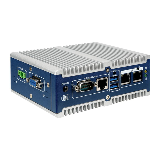
1.1 Overview Figure 1-1: ITG-100-AL The ITG-100-AL embedded system is a fanless system with one VGA port for display. It accepts an Intel® Atom™ x5-E3930 processor and supports one 204-pin DDR3L SO-DIMM module up to 8 GB (ITG-100-AL-E1/2GB/S and ITG-100-AL-E1/2GB SKUs are pre-installed with 2 GB memory). -
Page 16: Features
Two GbE LAN ports Two RS-232/422/485 Full-size PCIe Mini slot and M.2 A-key slot for expansion 1.4 Technical Specifications The ITG-100-AL technical specifications are listed in Table 1-2. Model Name ITG-100-AL-E1/S ITG-100-AL-E1 Chassis Color Blue & Silver Dimensions (WxDxH) 137 x 102.8 x 36.2 (mm) -
Page 17: Table 1-2: Technical Specifications
ITG-100-AL Embedded System USB 2.0 2 x USB 2.0 ports by pin-header (optional) 2 x RJ-45 PCIe GbE by I211-AT controller Ethernet COM Port 2 x RS-232/422/485 (DB-9/RJ45) 2 x RS-232 by pin-header (optional) Digital I/O 8-bit digital I/O, 4-bit input/4-bit output by pin-header (optional) -
Page 18: Side Panel
ITG-100-AL Embedded System 1.5 Side Panel The side panel of the ITG-100-AL has the following features (Figure 1-2): 1 x 12V DC IN 1 x VGA connector Figure 1-2: ITG-100-AL Side Panel 1.6 Front Panel The front panel of the ITG-100-AL has the following features (Figure 1-3): ... -
Page 19: Figure 1-3: Itg-100-Al Front Panel
ITG-100-AL Embedded System Figure 1-3: ITG-100-AL Front Panel Page 7... -
Page 20: Physical Dimensions
ITG-100-AL Embedded System 1.7 Physical Dimensions 1.7.1 ITG-100-AL-E1 Physical Dimensions The physical dimensions of the ITG-100-AL-E1 are shown below: Figure 1-4: ITG-100-AL-E1 Physical Dimensions (mm) Page 8... -
Page 21: Itg-100-Al-E1/S Physical Dimensions
ITG-100-AL Embedded System 1.7.1 ITG-100-AL-E1/S Physical Dimensions The physical dimensions of the ITG-100-AL-E1/S are shown below: Figure 1-5: ITG-100-AL-E1/S Physical Dimensions (mm) Page 9... -
Page 22: Unpacking
ITG-100-AL Embedded System Chapter Unpacking Page 10... -
Page 23: Unpacking
If some of the components listed in the checklist below are missing, please do not proceed with the installation. Contact the IEI reseller or vendor you purchased the ITG-100-AL from or contact an IEI sales representative directly. To contact an IEI sales representative, please send an email to sales@iei.com.tw. -
Page 24: Table 2-1: Package List Contents
ITG-100-AL Embedded System Quantity Item and Part Number Image SATA cable & SATA power cable (for ITG-100-AL-E1 only) Mounting Bracket Table 2-1: Package List Contents Page 12... -
Page 25: Installation
ITG-100-AL Embedded System Chapter Installation Page 13... -
Page 26: Anti-Static Precautions
Electric shock and personal injury might occur if the rear panel of the ITG-100-AL is opened while the power cord is still connected to an electrical outlet. -
Page 27: Installation And Configuration Steps
ITG-100-AL. The ITG-100-AL’s cooling vents must not be obstructed by any objects. Blocking the vents can cause overheating of the ITG-100-AL. Leave at least 5 cm of clearance around the ITG-100-AL to prevent overheating. Grounding: The ITG-100-AL should be properly grounded. The voltage feeds must not be overloaded. -
Page 28: Figure 3-1: Remove The Bottom Panel
ITG-100-AL Embedded System Figure 3-1: Remove the Bottom Panel Step 2: Open the bottom cover and remove the three retention screws from the HDD bracket (Figure 3-2). Figure 3-2: HDD Bracket Step 3: Attach the HDD to the HDD bracket. Secure the HDD with the HDD bracket by four retention screws (Figure 3-3). -
Page 29: So-Dimm Installation
3.4 SO-DIMM Installation WARNING: Using incorrectly specified SO-DIMM may cause permanently damage the ITG-100-AL. Please make sure the purchased SO-DIMM complies with the memory specifications of the ITG-100-AL. To install a SO-DIMM into a SO-DIMM socket, please follow the steps below. -
Page 30: Figure 3-4: So-Dimm Socket
Release the arms on the SO-DIMM socket. They clip into place and secure the SO-DIMM in the socket. Step 7: Install the bracket that was previously removed in the same position it was before. Step 8: Reinstall the bottom panel to the ITG-100-AL. Page 18... -
Page 31: Wireless Lan Module Installation (Optional)
(Figure 3-1). Step 2: Remove the two knockout holes for antenna installation. The two knockout holes are located on the rear panel of the ITG-100-AL as shown in Figure 3-6. Figure 3-6: Knockout Holes for Wireless Antenna Step 3: Locate the M.2 A key slot. -
Page 32: Figure 3-8: Inserting The Wlan Module
ITG-100-AL Embedded System Step 4: Insert into the socket at an angle. Line up the notch on the WLAN module with the notch on the slot. Slide the WLAN module into the slot at an angle of about 20º (Figure 3-8). -
Page 33: Figure 3-9: Securing Wlan Module And Connecting Rf Cables
ITG-100-AL Embedded System Figure 3-9: Securing WLAN Module and Connecting RF Cables Step 7: Remove the nut and washer from the SMA connector at the other end of the RF cable. Step 8: Insert the SMA connector to the antenna connector holes on the side panel. -
Page 34: Additional Block Layer Installation
With choices of adding a 2.5” SATA HDD/SSD bay, a knockout-hole layer with selectable I/O interface, or both of above-mentioned options, the ITG-100-AL could be modularized to what best fit users’ preferences and still remaining its compact size. -
Page 35: Figure 3-12: Additional Block Layer Installation
ITG-100-AL Embedded System Figure 3-12: Additional Block Layer Installation Step 3: Install the HDD bracket by securing the three retention screws (Figure 3-13). Figure 3-13: HDD Bracket Installation Step 4: Reinstall the bottom panel by securing the two retention screws (Figure 3-14). -
Page 36: At/Atx Mode Selection
Figure 3-14: Reinstall the Bottom Panel (ITG-100-AL-E1) 3.7 AT/ATX Mode Selection AT or ATX power mode can be used on the ITG-100-AL. The selection is made through an AT/ATX switch located on the front panel (Figure 3-15). To select AT mode or ATX mode, follow the steps below. -
Page 37: At Power Mode
Manufacturing shop flow 3.7.2 ATX Power Mode With the ATX mode selected, the ITG-100-AL panel PC goes in a standby mode when it is turned off. The panel PC can be easily turned on via network or a power switch in standby mode. -
Page 38: Powering On/Off The System
Power off the system: press the power button for 6 seconds Figure 3-17: Power Button Location 3.10 Mounting the System 3.10.1 Mounting the System with DIN Rail Mounting Kit To mount the ITG-100-AL embedded system onto a DIN rail, please follow the steps below. Page 26... -
Page 39: Figure 3-18: Mounting The Din Rail
ITG-100-AL Embedded System Step 1: Attach the DIN rail mounting bracket to the rear panel of the embedded system. Secure the bracket to the embedded system with the supplied retention screws (Figure 3-18). Figure 3-18: Mounting the DIN Rail Step 2:... -
Page 40: Rs-232/422/485 Serial Port Connection
DIN rail mounting kit. See Figure 3-19 3.11 RS-232/422/485 Serial Port Connection The ITG-100-AL has two RS-232/422/485 serial port connectors on the bottom panel. One is DB-9 connector and the other is RJ-45 connector. 3.11.1 DB-9 RS-232/422/485 Serial Port Connection DB-9 RS-232/422/485 serial port devices can be attached to the DB-9 port on the bottom panel. -
Page 41: Rs-232/422/485 Serial Port Connection
The RJ-45 RS-232/422/485 serial port connects to a cable with a standard DB-9 connector at the other end (cables included). Follow the steps below to connect a serial device to the ITG-100-AL. Step 1: Locate the RJ-45 connector. The location of the RJ-45 serial port connector is shown in Chapter 2. -
Page 42: Figure 3-22: Serial Device Connector
ITG-100-AL Embedded System Figure 3-22: Serial Device Connector Step 4: Secure the connector. Secure the serial device connector to the external interface by tightening the two retention screws on either side of the connector. Figure 3-23: RJ-45 RS-232/422/485 Serial Port Connector... -
Page 43: Figure 3-24: Db-9 Rs-232/422/485 Connector Pinout Location
ITG-100-AL Embedded System Figure 3-24: DB-9 RS-232/422/485 Connector Pinout Location RS-232 RS-422 RS-485 NDCD DATA- DATA+ NDTR NDSR NRTS NCTS Table 3-2: DB-9 RS-232/422/485 Connector Pinouts NOTE: The communication protocol of the serial ports is set through the BIOS menu in “Advanced ... -
Page 44: System Motherboard
ITG-100-AL Embedded System Chapter System Motherboard Page 32... -
Page 45: Overview
ITG-100-AL Embedded System 4.1 Overview This chapter details all the jumpers and connectors of the system motherboard. 4.1.1 Layout The figures below show all the connectors and jumpers of the system motherboard. The Pin 1 locations of the on-board connectors are also indicated in the diagram below. -
Page 46: Internal Peripheral Connectors
ITG-100-AL Embedded System 4.2 Internal Peripheral Connectors The table below shows a list of the internal peripheral interface connectors on the system motherboard. Pinouts of these connectors can be found in the following sections. Connector Type Label Battery connector 2-pin wafer... -
Page 47: Debug Connector (Dbg_Port1)
ITG-100-AL Embedded System 4.2.3 Debug Connector (DBG_PORT1) PIN NO. DESCRIPTION PIN NO. DESCRIPTION BUF_PLT_RST# LPC_TPM LPC_AD3 LPC_AD2 LPC_AD1 LPC_AD0 LPC_FRAME_N V3P3_S Table 4-4: Debug Connector Pinouts (DBG_PORT1) 4.2.4 DIO Connector (J_DIO2) PIN NO. DESCRIPTION PIN NO. DESCRIPTION V5_S DOUT3 DOUT2... -
Page 48: Serial Port Connector (Com4)
ITG-100-AL Embedded System Table 4-7: RS-232 Serial Port Connector Pinouts (COM3) 4.2.7 RS-232 Serial Port Connector (COM4) PIN NO. DESCRIPTION PIN NO. DESCRIPTION NDCD4 NDSR4 NRX4 NRTS4 NTX4 NCTS4 NDTR4 NRI4 Table 4-8: RS-232 Serial Port Connector Pinouts (COM4) 4.2.8 SMBUS/I2C Connector (J_SMB2) PIN NO. -
Page 49: Micro Sd Connector (Sd1)
ITG-100-AL Embedded System 4.2.11 Connector (SD1) Micro SD PIN NO. DESCRIPTION PIN NO. DESCRIPTION SD_D2 SD_CLK SD_D3 SD_CMD SD_D0 SD_V3P3 SD_D1 SD_CD# Table 4-12: Micro SD Connector Pinouts (SD1) 4.3 External Interface Panel Connectors The table below shows a list of the external interface panel connectors on the system motherboard. -
Page 50: Ethernet Connector (Lan2)
ITG-100-AL Embedded System TRD2P3 TRD2N3 LAN1_GND LAN1_GND +V3.3LAN1 L1_LINK_ACT- L1_100- L1_1000- Table 4-14: Ethernet Connector Pinouts (LAN1) 4.3.2 Ethernet Connector (LAN2) PIN NO. DESCRIPTION PIN NO. DESCRIPTION 2TRD2P0 2TRD2N0 2TRD2P1 2TRD2N1 1_5VLAN2 1_5VLAN2 2TRD2P2 2TRD2N2 2TRD2P3 2TRD2N3 LAN2_GND LAN2_GND +V3.3LAN2... -
Page 51: Rs-232/422/485 Connector (Com1)
ITG-100-AL Embedded System 4.3.5 RS-232/422/485 Connector (COM1) PIN NO. DESCRIPTION PIN NO. DESCRIPTION NDCD1 NDSR1 NRX1 NRTS1 NTX1 NCTS1 NDTR1 NRI1 Table 4-18: RS-232/422/485 Connector (COM1) 4.3.6 RJ45 to RS-232/422/485 Connector (COM2) PIN NO. DESCRIPTION PIN NO. DESCRIPTION NRI2 NRX2... -
Page 52: Vga Connector (Vga1)
ITG-100-AL Embedded System Table 4-20: USB 3.1 GEN 1 Connectors Pinouts (CON1) 4.3.8 VGA Connector (VGA1) PIN NO. DESCRIPTION PIN NO. DESCRIPTION CRT_VCC CRT_PLUG# 5VDDCDA 5HSYNC 5VSYNC 5VDDCLK Table 4-21: VGA Connector Pinouts (VGA1) 4.4 Jumper Settings The buttons, jumper and switch on the system motherboard are listed in Table 4-22. -
Page 53: Clear Cmos Button (J_Cmos1)
ITG-100-AL Embedded System 4.4.2 Clear CMOS Button (J_CMOS1) Setting Description Open Normal Operation (Default) Push Clear CMOS Setup Table 4-24: Clear CMOS Button (J_CMOS1) 4.4.3 System Reset Button (RST1) Setting Description Open Normal Operation (Default) Push System Restart Table 4-25: System Reset Button (RST1) 4.4.4 Flash Descriptor Security Override Jumper Settings (J_TXE1) -
Page 54: Bios
ITG-100-AL Embedded System Chapter BIOS Page 42... -
Page 55: Introduction
ITG-100-AL Embedded System 5.1 Introduction The BIOS is programmed onto the BIOS chip. The BIOS setup program allows changes to certain system settings. This chapter outlines the options that can be changed. NOTE: Some of the BIOS options may vary throughout the life cycle of the product and are subject to change without prior notice. -
Page 56: Getting Help
ITG-100-AL Embedded System Function Decrease the numeric value or make changes F1 key General help, only for Status Page Setup Menu and Option Page Setup Menu F2 key Load previous values. F3 key Load optimized defaults F4 key Save changes and Exit BIOS Esc key Main Menu –... -
Page 57: Main
ITG-100-AL Embedded System The following sections completely describe the configuration options found in the menu items at the top of the BIOS screen and listed above. 5.2 Main The Main BIOS menu (BIOS Menu 1) appears when the BIOS Setup program is entered. -
Page 58: Advanced
ITG-100-AL Embedded System System Date [xx/xx/xx] Use the System Date option to set the system date. Manually enter the day, month and year. System Time [xx:xx:xx] Use the System Time option to set the system time. Manually enter the hours, minutes and seconds. -
Page 59: Acpi Settings
ITG-100-AL Embedded System 5.3.1 ACPI Settings The ACPI Settings menu (BIOS Menu 3) configures the Advanced Configuration and Power Interface (ACPI) options. Aptio Setup Utility – Copyright (C) 2018 American Megatrends, Inc. Advanced ACPI Settings ACPI Sleep State [S3 (Suspend to RAM] ---------------------- : Select Screen... -
Page 60: F81866 Super Io Configuration
ITG-100-AL Embedded System 5.3.2 F81866 Super IO Configuration Use the F81866 Super IO Configuration menu (BIOS Menu 10) to set or change the configurations for the serial ports. Aptio Setup Utility – Copyright (C) 2018 American Megatrends, Inc. Advanced F81866 Super IO Configuration... - Page 61 ITG-100-AL Embedded System 5.3.2.1.1 Serial Port 1 Configuration Serial Port [Enabled] Use the Serial Port option to enable or disable the serial port. Disabled Disable the serial port Enable the serial port Enabled EFAULT Device Mode [RS232] Use the Device Mode option to select the serial port mode.
-
Page 62: Hardware Monitor
ITG-100-AL Embedded System 5.3.2.1.3 Serial Port 3 Configuration Serial Port [Enabled] Use the Serial Port option to enable or disable the serial port. Disabled Disable the serial port Enable the serial port Enabled EFAULT 5.3.2.1.4 Serial Port 4 Configuration ... -
Page 63: Rtc Wake Settings
ITG-100-AL Embedded System Aptio Setup Utility – Copyright (C) 2018 American Megatrends, Inc. Advanced PC Health Status CPU temperature :+39 °C SYS temperature :+42 °C VSCC_CPU :+0.808 V V5_S :+5.003 V V12_S :+12.056 V --------------------- : Select Screen V3P3_S :+3.312 V ↑... - Page 64 ITG-100-AL Embedded System Aptio Setup Utility – Copyright (C) 2018 American Megatrends, Inc. Advanced RTC Wake Settings Enable or disable System wake on alarm Wake system with Fixed Time [Disabled] event. When enabled, System will wake on the date::hr::min::sec specified --------------------- : Select Screen...
-
Page 65: Serial Port Console Redirection
ITG-100-AL Embedded System 5.3.5 Serial Port Console Redirection The Serial Port Console Redirection menu (BIOS Menu 8) allows the console redirection options to be configured. Console redirection allows users to maintain a system remotely by re-directing keyboard input and text output through the serial port. - Page 66 ITG-100-AL Embedded System Aptio Setup Utility – Copyright (C) 2018 American Megatrends, Inc. Advanced COM1 Emulation: ANSI: Console Redirection Settings Extended ASCII char set. VT100: ASCII char set. Terminal Type [ANSI] VT100+: Extends VT100 to Bits per second [115200] support color, function Data Bits keys, etc.
- Page 67 ITG-100-AL Embedded System 38400 Sets the serial port transmission speed at 38400. Sets the serial port transmission speed at 57600. 57600 115200 Sets the serial port transmission speed at 115200. EFAULT Data Bits [8] Use the Data Bits option to specify the number of data bits.
-
Page 68: Cpu Configuration
ITG-100-AL Embedded System 5.3.6 CPU Configuration Use the CPU Configuration menu (BIOS Menu 10) to view detailed CPU specifications and configure the CPU. Aptio Setup Utility – Copyright (C) 2018 American Megatrends, Inc. Advanced CPU Configuration When enabled, a VMM can utilize the additional Intel(R) Atom(TM) Processor E3930 @ 1.30GHz... -
Page 69: Usb Configuration
ITG-100-AL Embedded System Disabled Disables the Intel Speed Step Technology. Enables the Intel Speed Step Technology. Enabled EFAULT C-States [Disabled] Use the C-States option to enable or disable the CPU C state. Disabled Disables the CPU C state. -
Page 70: Iei Feature
ITG-100-AL Embedded System Legacy USB Support [Enabled] Use the Legacy USB Support BIOS option to enable USB mouse and USB keyboard support. Normally if this option is not enabled, any attached USB mouse or USB keyboard does not become available until a USB compatible operating system is fully booted with all USB drivers loaded. -
Page 71: Sata Configuration
ITG-100-AL Embedded System Disabled Disabled the auto recovery function EFAULT Enabled the auto recovery function Enabled 5.3.9 SATA Configuration Use the SATA Configuration menu (BIOS Menu 13) to change and/or set the configuration of the SATA devices installed in the system. -
Page 72: Chipset
ITG-100-AL Embedded System 5.4 Chipset Use the Chipset menu (BIOS Menu 14) to access the Northbridge and Southbridge configuration menus WARNING! Setting the wrong values for the Chipset BIOS selections in the Chipset BIOS menu may cause the system to malfunction. -
Page 73: North Bridge Configuration
ITG-100-AL Embedded System 5.4.1 North Bridge Configuration Use the North Bridge Configuration menu (BIOS Menu 15) to configure the Intel IGD settings. Aptio Setup Utility – Copyright (C) 2018 American Megatrends, Inc. Chipset Memory Information Configure Intel IGD Settings. Total Memory... - Page 74 ITG-100-AL Embedded System Aptio Setup Utility – Copyright (C) 2018 American Megatrends, Inc. Chipset Intel IGD Configuration Select which of IGD/PCI Graphics device should be Primary Display [IGD] Primary Display. DVMT Pre-Allocated [256M] DVMT Total Gfx Mem [Max] --------------------- : Select Screen ↑...
-
Page 75: Southbridge Configuration
ITG-100-AL Embedded System DVMT Total Gfx Mem [Max] Use the DVMT Total Gfx Mem option to select DVMT5.0 total graphic memory size used by the internal graphic device. The following options are available: 128M 256M Default 5.4.2 Southbridge Configuration... -
Page 76: Pci Express Configuration
ITG-100-AL Embedded System Power Saving Function (EUP) [Disabled] Use the Power Saving Function (EUP) option to enable or disable the power saving function. Disabled Power saving function is disabled. EFAULT Power saving function is enabled. It will reduce power Enabled consumption when the system is off. -
Page 77: Scc Configuration
ITG-100-AL Embedded System Disabled Disables the compliance mode. EFAULT Enables the compliance mode. Enabled The M.2 and MPCIE submenus all contain the following options: PCIe Speed [Auto] Use PCIe Speed option to select the speed type of the PCIe Mini slot. The following options are available: ... -
Page 78: Security
ITG-100-AL Embedded System Enabled Enables the SCC SD card support. EFAULT SCC eMMC Support [Enabled] Use the SCC eMMC Support option to enable or disable the SCC eMMC support. Disables the SCC eMMC support. Disabled Enabled Enables the SCC eMMC support. -
Page 79: Boot
ITG-100-AL Embedded System Administrator Password Use the Administrator Password to set or change a administrator password. User Password Use the User Password to set or change a user password. 5.6 Boot Use the Boot menu (BIOS Menu 19) to configure system boot options. - Page 80 ITG-100-AL Embedded System Does not enable the keyboard Number Lock automatically. To use the 10-keys on the keyboard, press the Number Lock key located on the upper left-hand corner of the 10-key pad. The Number Lock LED on the keyboard lights up when the Number Lock is engaged.
-
Page 81: Exit
ITG-100-AL Embedded System Disabled Boot from UEFI devices is disabled. EFAULT Boot Option Priority Use the Boot Option Priority function to set the system boot sequence from the available devices. The drive sequence also depends on the boot sequence in the individual device section. - Page 82 ITG-100-AL Embedded System Save Changes and Reset Use the Save Changes and Reset option to save the changes made to the BIOS options and to exit the BIOS configuration setup program. Discard Changes and Reset Use the Discard Changes and Reset option to exit the system without saving the changes made to the BIOS configuration setup program.
-
Page 83: Software Installation
ITG-100-AL Embedded System Chapter Software Installation Page 71... -
Page 84: Available Drivers
ITG-100-AL Embedded System 6.1.1 Available Drivers All the drivers for the ITG-100-AL are available on IEI Resource Download Center (https://download.ieiworld.com). Type ITG-100-AL and press Enter to find all the relevant software, utilities, and documentation. Figure 6-1: IEI Resource Download Center 6.1.2 Driver Download... - Page 85 ITG-100-AL Embedded System Step 7: Click the driver file name on the page and you will be prompted with the following window. You can download the entire ISO file ( ), or click the small arrow to find an individual driver and click the file name to download (...
-
Page 86: A Regulatory Compliance
ITG-100-AL Embedded System Appendix Regulatory Compliance Page 74... - Page 87 ITG-100-AL Embedded System DECLARATION OF CONFORMITY This equipment is in conformity with the following EU directives: EMC Directive (2004/108/EC, 2014/30/EU) Low-Voltage Directive (2006/95/EC, 2014/35/EU) RoHS II Directive (2011/65/EU, 2015/863/EU) If the user modifies and/or install other devices in the equipment, the CE conformity declaration may no longer apply.
- Page 88 ITG-100-AL Embedded System Deutsch [German] IEI Integration Corp, erklärt dieses Gerät entspricht den grundlegenden Anforderungen und den weiteren entsprechenden Vorgaben der Richtlinie 2014/53/EU. Eesti [Estonian] IEI Integration Corp deklareerib seadme seadme vastavust direktiivi 2014/53/EÜ põhinõuetele ja nimetatud direktiivist tulenevatele teistele asjakohastele sätetele.
- Page 89 ITG-100-AL Embedded System Lietuvių [Lithuanian] IEI Integration Corp deklaruoja, kad šis įranga atitinka esminius reikalavimus ir kitas 2014/53/EU Direktyvos nuostatas. Nederlands [Dutch] IEI Integration Corp dat het toestel toestel in overeenstemming is met de essentiële eisen en de andere relevante bepalingen van richtlijn 2014/53/EU.
- Page 90 ITG-100-AL Embedded System Slovensko [Slovenian] IEI Integration Corp izjavlja, da je ta opreme v skladu z bistvenimi zahtevami in ostalimi relevantnimi določili direktive 2014/53/EU. Slovensky [Slovak] IEI Integration Corp týmto vyhlasuje, že zariadenia spĺňa základné požiadavky a všetky príslušné ustanovenia Smernice 2014/53/EU.
- Page 91 ITG-100-AL Embedded System Federal Communication Commission Interference Statement This equipment has been assembled with components that comply with the limits for a Class B digital device, pursuant to Part 15 of the FCC Rules. These limits are designed to provide reasonable protection against harmful interference in a residential installation.
-
Page 92: B Safety Precautions
ITG-100-AL Embedded System Appendix Safety Precautions Page 80... -
Page 93: Safety Precautions
Electric shocks can occur if the ITG-100-AL chassis is opened when it is running. To avoid risk of electric shock, this device must only be connected to a supply mains with protective earth. -
Page 94: Anti-Static Precautions
Electrostatic discharge (ESD) can cause serious damage to electronic components, including the ITG-100-AL. Dry climates are especially susceptible to ESD. It is therefore critical that whenever the ITG-100-AL is opened and any of the electrical components are handled, the following anti-static precautions are strictly adhered to. -
Page 95: Product Disposal
ITG-100-AL Embedded System B.1.3 Product Disposal CAUTION: Risk of explosion if battery is replaced by an incorrect type. Only certified engineers should replace the on-board battery. Dispose of used batteries according to instructions and local regulations. Outside the European Union–If you wish to dispose of used electrical and electronic products outside the European Union, please contact your local authority so as to comply with the correct disposal method. -
Page 96: Maintenance And Cleaning Precautions
B.2.1 Maintenance and Cleaning Prior to cleaning any part or component of the ITG-100-AL, please read the details below. Except for the LCD panel, never spray or squirt liquids directly onto any other components. - Page 97 ITG-100-AL Embedded System can be used to clean the device. Using solvents–The use of solvents is not recommended when cleaning the device as they may damage the plastic parts. Vacuum cleaner–Using a vacuum specifically designed for computers is one of the best methods of cleaning the device.
-
Page 98: Cbios Menu Options
ITG-100-AL Embedded System Appendix BIOS Menu Options Page 86... - Page 99 ITG-100-AL Embedded System Below is a list of BIOS configuration options in the BIOS chapter. System Date [xx/xx/xx] ......................46 System Time [xx:xx:xx] ....................... 46 ACPI Sleep State [S3 only (Suspend to RAM)] ..............47 Serial Port [Enabled] ......................49 ...
- Page 100 ITG-100-AL Embedded System PCIe Speed [Auto] ........................ 65 SCC SD Card Support [Enabled] ..................65 SCC eMMC Support [Enabled] .................... 66 eMMC Max Speed [HS400] ....................66 Administrator Password ..................... 67 User Password ........................67 ...
-
Page 101: D Terminology
ITG-100-AL Embedded System Appendix Terminology Page 89... - Page 102 ITG-100-AL Embedded System AC ’97 Audio Codec 97 (AC’97) refers to a codec standard developed by Intel® in 1997. ACPI Advanced Configuration and Power Interface (ACPI) is an OS-directed configuration, power management, and thermal management interface. AHCI Advanced Host Controller Interface (AHCI) is a SATA Host controller register-level interface.
- Page 103 ITG-100-AL Embedded System Direct Memory Access (DMA) enables some peripheral devices to bypass the system processor and communicate directly with the system memory. DIMM Dual Inline Memory Modules are a type of RAM that offer a 64-bit data bus and have separate electrical contacts on each side of the module.
- Page 104 ITG-100-AL Embedded System Liquid crystal display (LCD) is a flat, low-power display device that consists of two polarizing plates with a liquid crystal panel in between. LVDS Low-voltage differential signaling (LVDS) is a dual-wire, high-speed differential electrical signaling system commonly used to connect LCD displays to a computer.
-
Page 105: E Hazardous Materials Disclosure
ITG-100-AL Embedded System Appendix Hazardous Materials Disclosure Page 93... - Page 106 ITG-100-AL Embedded System The details provided in this appendix are to ensure that the product is compliant with the Peoples Republic of China (China) RoHS standards. The table below acknowledges the presences of small quantities of certain materials in the product, and is applicable to China RoHS only.
- Page 107 ITG-100-AL Embedded System 此附件旨在确保本产品符合中国 RoHS 标准。以下表格标示此产品中某有毒物质的含量符 合中国 RoHS 标准规定的限量要求。 本产品上会附有”环境友好使用期限”的标签,此期限是估算这些物质”不会有泄漏或突变”的 年限。本产品可能包含有较短的环境友好使用期限的可替换元件,像是电池或灯管,这些元 件将会单独标示出来。 部件名称 有毒有害物质或元素 铅 汞 镉 六价铬 多溴联苯 多溴二苯 醚 (Pb) (Hg) (Cd) (CR(VI)) (PBB) (PBDE) 壳体 显示 印刷电路板 金属螺帽 电缆组装 风扇组装 电力供应组装 电池 O: 表示该有毒有害物质在该部件所有物质材料中的含量均在 SJ/T 11363-2006 (现由 GB/T 26572-2011 取代) 标准规定的限量要求以下。...
Need help?
Do you have a question about the ITG-100-AL and is the answer not in the manual?
Questions and answers