Table of Contents

Related Manuals for IEI Technology TANK-XM810 Series


Summary of Contents for IEI Technology TANK-XM810 Series
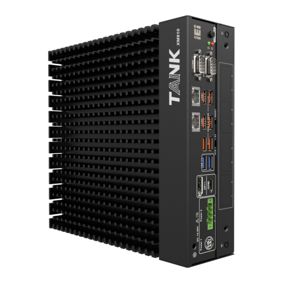
- Page 1 MODEL: TANK-XM810 Series Embedded System with 10th/11th Generation Intel® Core™ Processor, Two DDR4 Slot, Digital I/O, HDMI, DP, Two Gigabit Ethernet, RS-232/422/485, RoHS Compliant User Manual Rev. 1.01 – September 23, 2022...
- Page 2 TANK-XM810 Revisions Date Version Changes September 22, 2022 1.01 Added BIOS Section Added System Jumper Configuration in Section 4.4 Added RAID Configuration in Section 3.8 May 30, 2022 1.00 Initial release Page II...
- Page 3 TANK-XM810 Copyright COPYRIGHT NOTICE The information in this document is subject to change without prior notice in order to improve reliability, design and function and does not represent a commitment on the part of the manufacturer. In no event will the manufacturer be liable for direct, indirect, special, incidental, or consequential damages arising out of the use or inability to use the product or documentation, even if advised of the possibility of such damages.
- Page 4 TANK-XM810 Manual Conventions WARNING Warnings appear where overlooked details may cause damage to the equipment or result in personal injury. Warnings should be taken seriously. CAUTION Cautionary messages should be heeded to help reduce the chance of losing data or damaging the product. NOTE These messages inform the reader of essential but non-critical information.
-
Page 5: Table Of Contents
TANK-XM810 Table of Contents 1 INTRODUCTION ......................1 1.1 O ........................2 VERVIEW 1.2 M ....................3 ODEL ARIATIONS 1.3 F ........................3 EATURES 1.4 T ..................4 ECHNICAL PECIFICATIONS 1.5 F ......................6 RONT ANEL 1.6 R ....................... 7 ANEL 1.7 P .................... - Page 6 TANK-XM810 3.7 A ....................31 VAILABLE RIVERS 3.7.1 Driver Download ..................... 31 3.8 RAID C .................... 33 ONFIGURATION 3.9 M ......................36 AINTENANCE 3.9.1 Flash Descriptor Security Override Jumper ............ 37 4 SYSTEM MOTHERBOARD ..................38 4.1 O ........................ 39 VERVIEW 4.1.1 Layout ......................
- Page 7 TANK-XM810 5.1 I ......................52 NTRODUCTION 5.1.1 Starting Setup ....................52 5.1.2 Using Setup ...................... 53 5.1.2.1 Keyboard Navigation ................53 5.1.2.2 Touch Navigation ..................54 5.1.3 Getting Help ..................... 55 5.1.4 Unable to Reboot after Configuration Changes ..........55 5.1.5 BIOS Menu Bar ....................
- Page 8 TANK-XM810 5.4.2.2 SATA And RST Configuration ..............95 5.4.2.3 HD Audio Configuration ................96 5.5 S ......................... 97 ECURITY 5.6 B ........................98 5.6.1 Boot Configuration ..................98 5.6.2 Boot Option Priorities ..................99 5.7 S & E ......................100 A REGULATORY COMPLIANCE ................
- Page 9 TANK-XM810 List of Figures Figure 1-1: TANK-XM810 Series ....................2 Figure 1-2: Front Panel ........................6 Figure 1-3: Rear Panel ........................7 Figure 1-4: Physical Dimensions ....................8 Figure 3-1: Remove the Cover .....................18 Figure 3-2: Take out the motherboard ..................18 Figure 3-3: CPU Installation ......................19...
- Page 10 TANK-XM810 Figure 3-27: Create RAID Volume from the Main Menu ............35 Figure 3-28: Choose the RAID Level and select the Disks ............35 Figure 3-29: Confirm to create the RAID Volume ..............36 Figure 3-30 Flash Descriptor Security Override Jumper Location ..........37 Figure 4-1: System Motherboard (Front) ..................39 Figure 4-2: System Motherboard (Rear) ..................40 Figure 4-3: HDMI Connector ......................45...
- Page 11 TANK-XM810 List of Tables Table 1-1: TANK-XM810 Series Model Variations ............... 3 Table 1-2: Technical Specifications ....................5 Table 2-1: Standatd Packing List ....................12 Table 2-2: Optional Packing List ....................15 Table 3-1: Digital I/O Connector Pinouts ..................25 Table 3-2: RJ-45 Ethernet Connector LEDs ................27 Table 3-3: RS-232 (COM1~COM4) &...
- Page 12 TANK-XM810 Table 4-22: Power Input Connector Pinouts ................49 Table 4-23: Power Input Connector Pinouts ................49 Table 4-24: External Peripheral Connectors ................49 Table 4-25:AT/ATX Power Mode Switch Pinouts ...............50 Table 4-26: Clear CMOS Button Pinouts ..................50 Table 5-1: BIOS Navigation Keys ....................53 Table 5-2: BIOS On-screen Navigation Keys ................54 Table 5-3: BIOS Options and Configured USB Ports ..............92 Page XII...
-
Page 13: Introduction
TANK-XM810 Chapter Introduction Page 1... -
Page 14: Overview
260-pin DDR4 SDRAM SO-DIMM slots supporting up to 64GB memory (8GB preinstalled). The TANK-XM810 Series includes one digital I/O port, one HDMI, one DP++, two GbE LAN, six USB 3.2 Gen 2, two USB 2.0, two RS-232/422/485 and four RS-232 connectors. -
Page 15: Model Variations
TANK-XM810 1.2 Model Variations The model variations of the TANK-XM810 Series are listed below. Model No. Intel® Core™ i3-10320 3.8GHz TANK-XM810-i3BC-R10 (up to 4.6GHz, 4-core, TDP 65W) Intel® Core™ i5-10500TE 2.3GHz TANK-XM810-i5AC-R10 (up to 3.7GHz, 6-core, TDP 35W) Intel® Core™ i5-10500E 3.1GHz TANK-XM810-i5BC-R10 (up to 4.2GHz, 6-core, TDP 65W) -
Page 16: Technical Specifications
TANK-XM810 1.4 Technical Specifications The TANK-XM810 Series technical specifications are listed in Table 1-2 Specifications Chassis Color Black C Dimensions (WxDxH) (mm) 230.6 x 256.04 x 76.2 System Fan Fanless Chassis Construction Extruded aluminum alloy Motherboard 10/11th Gen. Intel® Core™ CPU: Intel®... -
Page 17: Table 1-2: Technical Specifications
TANK-XM810 Specifications Expansions 2 x 2280 M key (PCIe x2) Backplane Optional Power DC jack: 12 V~28 V DC Power Input Terminal block: 12 V~28 V DC Power Consumption 12V @ 8.8A (Intel ® Core™ i9-10900TE with 16GB memory) Remote Power 1 x 2-pin Reliability Mounting... -
Page 18: Front Panel
TANK-XM810 1.5 Front Panel The front panel of the TANK-XM810 Series has the following features (See Figure 1-2): Figure 1-2: Front Panel Page 6... -
Page 19: Rear Panel
TANK-XM810 1.6 Rear Panel The rear panel of the TANK-XM810 Series is shown below (See Figure 1-3): Figure 1-3: Rear Panel Page 7... -
Page 20: Physical Dimensions
TANK-XM810 1.7 Physical Dimensions The physical dimensions of the TANK-XM810 are shown below (See Figure 1-4): Figure 1-4: Physical Dimensions Page 8... -
Page 21: Unpacking
TANK-XM810 Chapter Unpacking Page 9... -
Page 22: Anti-Static Precautions
Electrostatic discharge (ESD) can cause serious damage to electronic components, including the TANK-XM810 Series. Dry climates are especially susceptible to ESD. It is therefore critical that whenever the TANK-XM810 Series or any other electrical component is handled, the following anti-static precautions are strictly adhered to. -
Page 23: Unpacking Checklist
If some of the components listed in the checklist below are missing, please do not proceed with the installation. Contact the IEI reseller or vendor you purchased the TANK-XM810 Series from or contact an IEI sales representative directly. To contact an IEI sales representative, please send an email to sales@ieiworld.com. -
Page 24: Table 2-1: Standatd Packing List
TANK-XM810 Quantity Item and Part Number Image Standard 2-pin Terminal block 4-pin Terminal block Chassis screws Table 2-1: Standatd Packing List The following table lists the optional items that can be purchased separately. Optional Wi-Fi module (P/N: EMB-WIFI-KIT02I3-R10) Page 12... - Page 25 TANK-XM810 Optional Power adapter (P/N: 63040-010180-200-RSSS) Power cord (P/N: 32000-000002-RS) 8-Port POE LAN Card (P/N: GPOE-XM81-8P-R10) M.2 & PCIe Mini expansion card (P/N: TXIOB-XM81-A-R10) 2-Slot Backplane (PCIe x16 & PCIe x4) (P/N: TXCBP-XM81-2A-R10) 2-Slot Backplane (Two PCIe x8) (P/N: TXCBP-XM81-2B-R10)ss Page 13...
- Page 26 TANK-XM810 Optional 4-Slot Backplane (PCIe x16 & Two PCIe x4 & PCIe x1) (P/N: TXCBP-XM81-4A-R10) 4-Slot Backplane (Two PCIe x8 & Two PCIe x4) (P/N: TXCBP-XM81-4B-R10) 4-Slot Backplane (PCIe x16 & PCIe x4 & Two PCI) (P/N: TXCBP-XM81-4C-R10) 4-Slot Backplane (PCIe x16 & Two PCIe x4 & PCIe x1) (P/N: TXCBP-XM81-G1-PW-R10) 4-Slot Backplane (Two PCIe x8 &...
-
Page 27: Table 2-2: Optional Packing List
TANK-XM810 Optional 3-Slot Chassis (P/N: TXC-XM81-3S-R10) 4-Slot Chassis (P/N: TXC-XM81-4S-R10) 4-Slot Chassis (Full-length graphics card support) (P/N: TXC-XM81-G1-R10) 6-Slot Chassis (Two Full-length graphics card support) (P/N: TXC-XM81-G2-R10) Expansion Fan Module (P/N: SF-TANK-XM81-R10) Table 2-2: Optional Packing List NOTE: 1.EMB-WIFI-KIT02I3-R10 needs to be used with TXIOB-XM81-A-R10. 2.TXCBP-XM81 series backplane needs to be used with TXC-XM81 series chassis Page 15... -
Page 28: Installation
TANK-XM810 Chapter Installation Page 16... -
Page 29: Installation Precautions
Electric shock and personal injury might occur if the rear panel of the TANK-XM810 Series is opened while the power cord is still connected to an electrical outlet. -
Page 30: Cpu/Ram/Storage Installation
TANK-XM810 3.2 CPU/RAM/Storage Installation To install the CPU /RAM/ Storage, please follow the steps below: Step 1: Remove the 6 screws on the side, and then remove the top cover (See Figure 3-1). Figure 3-1: Remove the Cover Step 2: Remove the 11 spring screws on the motherboard, and then take out the motherboard (including the motherboard holder) (See Figure 3-2). -
Page 31: Figure 3-3: Cpu Installation
TANK-XM810 Step 3: Pull the lever of the CPU buckle, remove the CPU protection cover, install the CPU at the notch, and fasten the lever down in the buckle (See Figure 3-3). Figure 3-3: CPU Installation Step 4: Place a thermal pad on the heat conductive block of CPU (See Figure 3-4). Figure 3-4: CPU Thermal Pad Installation Page 19... -
Page 32: Figure 3-5: Motherboard Installation
TANK-XM810 Step 5: Align the motherboard (together with the motherboard holder) with the 4 positioning rods on the 2 sides, place it on the heat sink, and lock the motherboard with 11 spring screws. (See Figure 3-5) Figure 3-5: Motherboard Installation Step 6: Insert the memory into the motherboard memory slot and press it into place (See Figure 3-6) -
Page 33: Figure 3-7: M.2 Installation
TANK-XM810 Figure 3-7: M.2 Installation Step 8: Place the hard drive into the hard drive bracket and secure the HDD bracket and the hard drive with four screws (See Figure 3-8) Figure 3-8: HDD Installation Step 9: Install the back cover. And lock the 6 screws on the side (See Figure 3-9) Page 21... -
Page 34: Mounting The System With Mounting Brackets
TANK-XM810 Figure 3-9: Back Cover Installation 3.3 Mounting the System with Mounting Brackets To mount the embedded system onto a wall or some other surface using the two mounting brackets, please follow the steps below. Step 1: Turn the embedded system over. Step 2: Align the retention screw holes in each bracket with the corresponding retention screw holes on the bottom surface... -
Page 35: External Peripheral Interface Connectors
Insert four retention screws, three in each bracket, to secure the system to the wall. 3.4 External Peripheral Interface Connectors The TANK-XM810 Series has the following connectors. Detailed descriptions of the connectors can be found in the subsections below. ... -
Page 36: At/Atx Power Mode Selection
TANK-XM810 3.4.1 AT/ATX Power Mode Selection The TANK-XM810 Series supports AT and ATX power modes. The setting can be made through the AT/ATX power mode switch on the external peripheral interface panel as shown below (See Figure 3-11). Figure 3-11: AT/ATX Power Mode Switch 3.4.2 SYS_FAN Connector... -
Page 37: Digital Input / Output Connector
TANK-XM810 3.4.3 Digital Input / Output Connector The digital I/O connector provides programmable input and output for external devices. The pinouts for the digital I/O connector are listed in the table below (See Table 3-1 & Figure 3-13). PIN NO. DESCRIPTION PIN NO. -
Page 38: Lan Connectors
Figure 3-16. Step 2: Align the connectors. Align the RJ-45 connector on the LAN cable with one of the RJ-45 connectors on the TANK-XM810 Series. (See Figure 3-15). Figure 3-15: LAN Connection Step 3: Insert the LAN cable RJ-45 connector. Once aligned, gently insert the LAN cable RJ-45 connector into the on-board RJ-45 connector. -
Page 39: Power Input, 4-Pin Terminal Block
TANK-XM810 Activity/Link LED Speed LED DESCRIPTION STATUS DESCRIPTION STATUS No link 100 Mbps connection SSYellow Linked Orange 1 Gbp connection Blinking TX/RX activity Green 2.5 Gbps connection Table 3-2: RJ-45 Ethernet Connector LEDs 3.4.6 Power Input, 4-pin Terminal Block The power connector connects the leads of a 12 V ~ 28 V DC power supply into the terminal block. -
Page 40: Rs-232/422/485 Serial Port Connection
TANK-XM810 3.4.8 DB-9 RS-232/422/485 Serial Port Connection The system has two RS-232 serial ports and two RS-422/485 serial ports. The pinouts for the serial ports are listed in the Table 3-3. PIN NO. RS232 RS422 RS485 DCD# DTR# DSR# RTS# CTS# Table 3-3: RS-232 (COM1~COM4) &... -
Page 41: Remote Power Connector
TANK-XM810 3.4.9 Remote Power Connector This remote power switch connector can be connected to an external switch for remote control of power on and off (See Figure 3-21). Figure 3-21: Remote Power Connector 3.5 Powering On/Off the System WARNING: Make sure a power supply with the correct input voltage is being fed into the system. -
Page 42: Power
TANK-XM810 3.6 Power There are two power connectors on the rear panel. Power 1 connector is a 4-pin terminal block that supports ACC On signal. Power 2 connector is a DIN connector that can directly connect to a power adapter. The supported power input voltages are: ... -
Page 43: Available Drivers
TANK-XM810 3.7 Available Drivers All the drivers for the TANK-XM810 Series are available on IEI Resource Download Center (https://download.ieiworld.com). Type TANK-XM810 Series and press Enter to find all the relevant software, utilities, and documentation. Figure 3-24: IEI Resource Download Center 3.7.1 Driver Download... - Page 44 TANK-XM810 Step 3: Click the driver file name on the page and you will be prompted with the following window. You can download the entire ISO file ( ), or click the small arrow to find an individual driver and click the file name to download ( NOTE: To install software from the downloaded ISO image file in Windows 10 (or later), double-click the ISO file to mount it as a virtual drive to view...
-
Page 45: Raid Configuration
TANK-XM810 3.8 RAID Configuration The TANK-XM810 Series can provide data protection for using two NVMe (PCIe) disks ® via the Intel® Rapid Storage Technology. To access the Intel Rapid Storage Technology, please follow the steps below. WARNING! Irrecoverable data loss occurs if a working drive is removed when trying to remove a failed drive. -
Page 46: Figure 3-25: Raid Configuration-Bios Setting (1)
TANK-XM810 Step 2: Enable the drives in BIOS. Start the computer and access the BIOS setup program. Go to Chipset PCH-IO Configuration SATA and RST Configuration SATA Mode Selection. Enable RAID support for all devices (See Figure 3-25). Figure 3-25: RAID Configuration–BIOS Setting (1) Step 3: Save and Exit BIOS. -
Page 47: Figure 3-27: Create Raid Volume From The Main Menu
TANK-XM810 Step 6: Select the option to Create RAID Volume from the Main Menu and press Enter. Figure 3-27: Create RAID Volume from the Main Menu Step 7: Press the up/down arrows on the keyboard to choose the RAID Level and select the disks for the RAID configuration. -
Page 48: Maintenance
TANK-XM810 Step 8: Create RAID Volume. Highlight Create Volume and press Enter, then choose Y when the warning prompt appears to create volume. (See Figure 3-29) Figure 3-29: Confirm to create the RAID Volume 3.9 Maintenance To configure the jumper settings, please follow the steps below. Step 1: Remove the top cover. -
Page 49: Flash Descriptor Security Override Jumper
TANK-XM810 3.9.1 Flash Descriptor Security Override Jumper The Descriptor Security Override jumper (J_FLASH1) allows users to enable or disable the ME firmware update. Refer to Figure 3-30 and Table 3-5 for the jumper location and settings. Setting Description Short 1-2 Disabled (default) Short 2-3 Enabled... -
Page 50: System Motherboard
TANK-XM810 Chapter System Motherboard Page 38... -
Page 51: Overview
TANK-XM810 4.1 Overview This chapter details all the jumpers and connectors of the system motherboard. 4.1.1 Layout The figures below show all the connectors and jumpers of the system motherboard. Figure 4-1: System Motherboard (Front) Page 39... -
Page 52: Figure 4-2: System Motherboard (Rear)
TANK-XM810 Figure 4-2: System Motherboard (Rear) Page 40... -
Page 53: Internal Peripheral Connectors
TANK-XM810 4.2 Internal Peripheral Connectors The table below shows a list of the internal peripheral interface connectors on the system motherboard. Pinouts of these connectors can be found in the following sections. Connector Type Label Battery connector 2-pin header BAT1 Power button connector 2-pin header PWR_BTN1... -
Page 54: I2C Bus Connector (I2C1)
TANK-XM810 4.2.1 I2C BUS connector (I2C1) PIN NO. DESCRIPTION PIN NO. DESCRIPTION I2C_DAT_CONN I2C_CLK_CONN +V5S Table 4-2: I2C Bus Connector Pinouts 4.2.2 SMBUS Connector (SMB1) PIN NO. DESCRIPTION PIN NO. DESCRIPTION SMB_DATA_MAIN SMB_CLK_MAIN +V5S Table 4-3: SMBus Connector Pinouts 4.2.3 BIOS Programming Connector (JSPI1) PIN NO. -
Page 55: Power Button Connector (Pwr_Btn1)
TANK-XM810 4.2.5 Power Button Connector (PWR_BTN1) PIN NO. DESCRIPTION PIN NO. DESCRIPTION PWRBTN_SW# Table 4-6: Power Button Connector Pinouts 4.2.6 EC UART Debug (EC_UART1) PIN NO. DESCRIPTION PIN NO. DESCRIPTION DEBUG_UART_TX +V3.3A_EC DEBUG_UART_RX Table 4-7: EC UART Debug Connector Pinouts 4.2.7 EC Debug Card Connector (DEBUG_SPI1) PIN NO. -
Page 56: External Interface Panel Connectors
TANK-XM810 4.3 External Interface Panel Connectors The table below shows a list of the external interface panel connectors on the system motherboard. Pinouts of these connectors can be found in the following sections. Connector Type Label Power input connector 4-pin DC jack PWR3 Power input connector 4-pin terminal block... -
Page 57: Hdmi Connector (Hdmi1)
TANK-XM810 4.3.1 HDMI Connector (HDMI1) PIN NO. DESCRIPTION PIN NO. DESCRIPTION HDMI_DATA2 HDMI_DATA2# HDMI_SCL HDMI_DATA1 HDMI_SDA HDMI_DATA1# HDMI_DATA0 HDMI_HPD HDMI_GND HDMI_DATA0# HDMI_GND HDMI_CLK HDMI_GND HDMI_GND HDMI_CLK# Table 4-12: HDMI Connector Pinouts Figure 4-3: HDMI Connector 4.3.2 DP++ Connector (DP1) PIN NO. DESCRIPTION PIN NO. -
Page 58: Usb 3.2 Gen 2 Connectors (Con1)
TANK-XM810 Figure 4-4: DP++ Connector 4.3.3 USB 3.2 Gen 2 Connectors (CON1) The system has two USB 3.2 Gen 2 (10Gb/s) connectors. PIN NO. DESCRIPTION PIN NO. DESCRIPTION USB_DATA- USB_DATA- USB_DATA+ USB_ DATA+ USB3_RX- USB3_RX- USB3_RX+ USB3_ RX+ USB3_TX- USB3_TX- USB3_TX+ USB3_TX+ Table 4-14: USB 3.2 Gen 2 Connector Pinouts... -
Page 59: Rs-232/422/485 Serial Port Connectors (Cn1: Com5/6)
TANK-XM810 Figure 4-5: USB 2.0 Connector 4.3.5 RS-232/422/485 Serial Port Connectors (CN1: COM5/6) Mode RS-232 RS-422 RS-485 PIN NO. DESCRIPTION DESCRIPTION DESCRIPTION DCD# DTR# DSR# RTS# CTS# Table 4-16: RS-232/422/485 Serial Port Connector Pinouts Figure 4-6: RS-232/422/485 Serial Port Connectors Page 47... -
Page 60: Connectors (Com1 ~ Com4)
TANK-XM810 4.3.6 RS-232 Connectors (COM1 ~ COM4) PIN NO. DESCRIPTION PIN NO. DESCRIPTION NDCD NDSR NRTS NCTS NDTR Table 4-17: RS-232 Connector Pinouts 4.3.7 LAN Connectors PIN NO. DESCRIPTION PIN NO. DESCRIPTION MDIA3- MDIA1+ MDIA3+ MDIA2+- MDIA2- MDIA0- MDIA1- MDIA0+ Table 4-18: LAN Connector Pinouts Figure 4-7: Ethernet Connector Description... -
Page 61: System Fan Connectors (Fan1)
TANK-XM810 4.3.9 System Fan Connectors (FAN1) PIN NO. DESCRIPTION PIN NO. DESCRIPTION VCC12V FANIO Table 4-21: System Fan Connectors Pinouts 4.3.10 Power Input Connector, DC Jack (PWR3) PIN NO. DESCRIPTION PIN NO. DESCRIPTION DC_IN1 DC_IN1 Table 4-22: Power Input Connector Pinouts 4.3.11 Power Input Connector, Terminal Block (PWR2) PIN NO. -
Page 62: At/Atx Power Mode Setting (J_Atx_At1)
TANK-XM810 4.4.1 AT/ATX Power Mode Setting (J_ATX_AT1) Use the J_ATX_AT1 switch to specify the systems power mode as AT or ATX PIN NO. DESCRIPTION 1-2 (Right) ATX Power Mode (default) 2-3 (Left) AT Power Mode Table 4-25:AT/ATX Power Mode Switch Pinouts Figure 4-8: AT/ATX Power Mode Switch 4.4.2 Clear CMOS Setup (J_CMOS1) To clear the CMOS Setup (for example if you have forgotten the password, you should... -
Page 63: Bios
TANK-XM810 Chapter BIOS Page 51... -
Page 64: Introduction
TANK-XM810 5.1 Introduction The BIOS is programmed onto the BIOS chip. The BIOS setup program allows changes to certain system settings. This chapter outlines the options that can be changed. NOTE: Some of the BIOS options may vary throughout the life cycle of the product and are subject to change without prior notice. -
Page 65: Using Setup
TANK-XM810 5.1.2 Using Setup The BIOS Setup menu can be navigated by using a keyboard or a touchscreen. 5.1.2.1 Keyboard Navigation For keyboard navigation, use the navigation keys shown in Table 5-1. Function Up arrow Move to previous item Down arrow Move to next item Left arrow Move to the item on the left hand side... -
Page 66: Touch Navigation
TANK-XM810 5.1.2.2 Touch Navigation For touchscreen navigation, use the on-screen navigation keys shown below. BIOS Menu 2: Touch Navigation On-screen Button Function Previous Values Load the last value you set. Optimized Defaults Load the factory default values in order to achieve the best performance. -
Page 67: Getting Help
TANK-XM810 5.1.3 Getting Help When F1 is pressed a small help window describing the appropriate keys to use and the possible selections for the highlighted item appears. To exit the Help Window, press the key. 5.1.4 Unable to Reboot after Configuration Changes If the computer cannot boot after changes to the system configuration is made, CMOS defaults. -
Page 68: Main
TANK-XM810 5.2 Main The Main BIOS menu appears when the BIOS Setup program is entered. The Main menu gives an overview of the basic system information. BIOS Menu 3: Main (1/2) Page 56... - Page 69 TANK-XM810 BIOS Menu 4: Main (2/2) Page 57...
- Page 70 TANK-XM810 BIOS Information The BIOS Information lists a brief summary of the BIOS. The fields in BIOS Information cannot be changed. The items shown in the system overview include: BIOS Vendor: Installed BIOS vendor Core Version: Current BIOS version ...
- Page 71 TANK-XM810 Name: Displays the PCH name PCH SKU: Displays the PCH SKU Stepping: Displays the PCH stepping Dual Output Fast Read Support: Displays the support of dual output fast read Read ID/Status Clock Freq: Displays the frequency of reading ID and status clock frequency ...
-
Page 72: Advanced
TANK-XM810 5.3 Advanced Use the Advanced menu (BIOS Menu 5) to configure the CPU and peripheral devices through the following sub-menus: WARNING! Setting the wrong values in the sections below may cause the system to malfunction. Make sure that the settings made are compatible with the hardware. -
Page 73: Cpu Configuration
TANK-XM810 5.3.1 CPU Configuration Use the CPU Configuration menu (BIOS Menu 6 & BIOS Menu 7) to view detailed CPU specifications or enable the Intel Virtualization Technology. BIOS Menu 6: CPU Configuration (1/2) Page 61... - Page 74 TANK-XM810 BIOS Menu 7: CPU Configuration (2/2) Intel (VMX) Virtualization Technology [Enabled] Use the Intel (VMX) Virtualization Technology option to enable or disable virtualization on the system. When combined with third party software, Intel® Virtualization technology allows several OSs to run on the same system at the same time. ...
- Page 75 TANK-XM810 Active Processor Cores [All] Use the Active Processor Cores BIOS option to enable numbers of cores in the processor package. Enable all cores in the processor package. EFAULT Enable one core in the processor package. Enable two cores in the processor package.
- Page 76 TANK-XM810 C states [Disabled] Use the C states option to enable or disable CPU power management which allows CPU to go to C states when it is not 100% utilized. Disables CPU power management Disabled EFAULT Enabled Enables CPU power management ...
-
Page 77: Trusted Computing
TANK-XM810 5.3.2 Trusted Computing Use the Trusted Computing menu (BIOS Menu 8) to configure settings related to the Trusted Computing Group (TCG) Trusted Platform Module (TPM). BIOS Menu 8: PCH-FW Configuration Security Device Support [Enabled] Use the Security Device Support option to configure support for the TPM. ... -
Page 78: Rtc Wake Settings
TANK-XM810 5.3.3 RTC Wake Settings The RTC Wake Settings menu (BIOS Menu 9) configures RTC wake event. BIOS Menu 9: RTC Wake Settings Wake System with Fixed Time [Disabled] Use the Wake System with Fixed Time option to specify the time the system should be roused from a suspended state. -
Page 79: F81866 Super Io Configuration
TANK-XM810 *Wake up minute *Wake up second *Wake After setting the alarm, the computer turns itself on from a suspend state when the alarm goes off. 5.3.4 F81866 Super IO Configuration Use the F81866 Super IO Configuration menu (BIOS Menu 10) to set or change the configurations for the serial ports. -
Page 80: Serial Port 1 Configuration
TANK-XM810 5.3.4.1 Serial Port 1 Configuration Use the Serial Port 1 Configuration menu (BIOS Menu 11) to configure the serial port 1. BIOS Menu 11: Serial Port 1 Configuration Menu Serial Port [Enabled] Use the Serial Port option to enable or disable the serial port. ... -
Page 81: Serial Port 2 Configuration
TANK-XM810 5.3.4.2 Serial Port 2 Configuration Use the Serial Port 2 Configuration menu (BIOS Menu 12) to configure the serial port 2. BIOS Menu 12: Serial Port 2 Configuration Menu Serial Port [Enabled] Use the Serial Port option to enable or disable the serial port. ... -
Page 82: Serial Port 3 Configuration
TANK-XM810 5.3.4.3 Serial Port 3 Configuration Use the Serial Port 3 Configuration menu (BIOS Menu 13) to configure the serial port 3. BIOS Menu 13: Serial Port 3 Configuration Menu Serial Port [Enabled] Use the Serial Port option to enable or disable the serial port. ... -
Page 83: Serial Port 4 Configuration
TANK-XM810 5.3.4.4 Serial Port 4 Configuration Use the Serial Port 4 Configuration menu (BIOS Menu 14) to configure the serial port 4. BIOS Menu 14: Serial Port 4 Configuration Menu Serial Port [Enabled] Use the Serial Port option to enable or disable the serial port. ... -
Page 84: Serial Port 5 Configuration
TANK-XM810 5.3.4.5 Serial Port 5 Configuration Use the Serial Port 5 Configuration menu (BIOS Menu 15) to configure the serial port 5. BIOS Menu 15: Serial Port 5 Configuration Menu Serial Port [Enabled] Use the Serial Port option to enable or disable the serial port. ... -
Page 85: Serial Port 6 Configuration
TANK-XM810 Device Mode [Printer Mode] Use the Device Mode option to select the Serial Port 5 signaling mode. Configuration options are listed below. Serial Port 5 signaling mode is RS-232 RS232 EFAULT RS422 Serial Port 5 signaling mode is RS-422 ... -
Page 86: Ene Kb9068 Monitor
TANK-XM810 Serial Port [Enabled] Use the Serial Port option to enable or disable the serial port. Disable the serial port Disabled Enabled Enable the serial port EFAULT Device Settings The Device Settings option shows the serial port IO port address and interrupt address. ... - Page 87 TANK-XM810 BIOS Menu 17: ENE KB9068 Monitor PC Health Status The following system parameters and values are shown. The system parameters that are monitored are: System Temperatures: CPU Temperature System Temperature Fan Speeds: CPU_FAN1 Speed SYS_FAN1 Speed SYS_FAN2 Speed ...
-
Page 88: Smart Fan Mode Configuration
TANK-XM810 5.3.5.1 Smart Fan Mode Configuration Use the Smart Fan Mode Configuration submenu (BIOS Menu 18) to configure the CPU/system fan start/off temperature and control mode. BIOS Menu 18: Smart Fan Mode Configuration Page 76... - Page 89 TANK-XM810 CPU_FAN1/SYS_FAN1/SYS_FAN2 Smart Fan Control [Auto Mode] Use the CPU_FAN1/SYS_FAN1 Smart Fan Control option to configure the CPU Smart Fan. The fan spins at the speed set in Manual Mode Manual Mode settings. Auto Mode The fan adjusts its speed using Auto Mode EFAULT settings.
-
Page 90: Serial Port Console Redirection
TANK-XM810 5.3.6 Serial Port Console Redirection The Serial Port Console Redirection menu (BIOS Menu 19) allows the console redirection options to be configured. Console Redirection allows users to maintain a system remotely by re-directing keyboard input and text output through the serial port. BIOS Menu 19: Serial Port Console Redirection Page 78... -
Page 91: Console Redirection Settings
TANK-XM810 Console Redirection [Disabled] Use Console Redirection option to enable or disable the console redirection function. Disabled the console redirection function Disabled EFAULT Enabled Enabled the console redirection function The Console Redirection Settings submenu will be available when the Console Redirection option is enabled. - Page 92 TANK-XM810 Terminal Type [ANSI] Use the Terminal Type option to specify the remote terminal type. VT100 The target terminal type is VT100 VT100+ The target terminal type is VT100+ VT-UTF8 The target terminal type is VT-UTF8 ...
- Page 93 TANK-XM810 No parity bit is sent with the data bits. None EFAULT Even The parity bit is 0 if the number of ones in the data bits is even. The parity bit is 0 if the number of ones in the data bits is odd.
-
Page 94: Intel Txt Information
TANK-XM810 5.3.7 Intel TXT Information The Intel TXT Information menu (BIOS Menu 21) displays the Intel Trusted Execution Technology information. BIOS Menu 21: Intel TXT Information Intel TXT Information The Intel TXT Information lists a brief summary of the Intel Trusted Execution Technology. -
Page 95: Nvme Configuration
TANK-XM810 Error Code: Displays the Intel TXT shutdown error code. Class Code: Displays the Intel TXT shutdown class code. Major Code: Displays the Intel TXT shutdown major code. Minor Code: Displays the Intel TXT shutdown minor code. 5.3.8 NVMe Configuration Use the NVMe Configuration (BIOS Menu 22) menu to display the NVMe controller and device information. -
Page 96: Chipset
TANK-XM810 5.4 Chipset Use the Chipset menu (BIOS Menu 23) to access the PCH IO and System Agent (SA) configuration menus. WARNING! Setting the wrong values for the Chipset BIOS selections in the Chipset BIOS menu may cause the system to malfunction. BIOS Menu 23: Chipset Page 84... -
Page 97: System Agent (Sa) Configuration
TANK-XM810 5.4.1 System Agent (SA) Configuration Use the System Agent (SA) Configuration menu (BIOS Menu 24) to configure the System Agent (SA) parameters. BIOS Menu 24: System Agent (SA) Configuration VT-d [Enabled] Use the VT-d option to enable or disable the VT-d capability. ... -
Page 98: Memory Configuration
TANK-XM810 VCRt mapping to PEG [Enabled] Use the VCRt mapping to PEG option to enable or disable the capability of mapping VCRt to PEG. Disable the VCRt capability Disabled Enabled Enable the VCRt capability EFAULT 5.4.1.1 Memory Configuration Use the Memory Configuration submenu (BIOS Menu 25) to view memory information. -
Page 99: Graphics Configuration
TANK-XM810 5.4.1.2 Graphics Configuration Use the Graphics Configuration (BIOS Menu 26) menu to configure the video device connected to the system. BIOS Menu 26: Graphics Configuration Primary Display [Auto] Use the Primary Display option to select the primary graphics controller the system uses. The following options are available: ... - Page 100 TANK-XM810 Internal Graphics [Enabled] Use the Internal Graphics option to configure whether to keep IGFX enabled. If user wants to support dual display by internal graphics and external graphics, this Internal Graphics option should be set to Enabled and the above Primary Display option should be set to IGFX.
-
Page 101: Peg Port Configuration
TANK-XM810 5.4.1.3 PEG Port Configuration Use the PEG Port Configuration menu (BIOS Menu 27) to configure the PCI Express Configuration settings. BIOS Menu 27: PEG Port Configuration Enable Root Port [Auto] Use the Enable Root Port option to enable or disable the PCI Express (PEG) controller. ... -
Page 102: Peg Port Feature Configuration
TANK-XM810 5.4.1.3.1 PEG Port Feature Configuration Use the PEG Port Feature Configuration submenu (BIOS Menu 28) to configure the SA PCIe settings. BIOS Menu 28: PEG Port Feature Configuration Detect Non-Compliance Device [Disabled] Use the Detect Non-Compliance Device option to detect non-compliance PCIe device in PEG. -
Page 103: Pch-Io Configuration
TANK-XM810 5.4.2 PCH-IO Configuration Use the PCH-IO Configuration menu (BIOS Menu 29) to configure the PCH parameters. BIOS Menu 29: PCH-IO Configuration Auto Power Button Function [Disabled(ATX)] Use the Auto Power Button Function BIOS option to show the power mode state. Use the J_ATX_AT1 to switch the AT/ATX power mode. -
Page 104: Table 5-3: Bios Options And Configured Usb Ports
TANK-XM810 The system turns on Power On Last State The system returns to its previous state. If it was on, it EFAULT turns itself on. If it was off, it remains off. Power Saving Function(EUP) [Disabled] Use the Power Saving Function(EUP) BIOS option to enable or disable the power saving function. -
Page 105: Pci Express Configuration
TANK-XM810 5.4.2.1 PCI Express Configuration Use the PCI Express Configuration submenu (BIOS Menu 30) to configure the PCI Express Root Port Settings. BIOS Menu 30: PCI Express Configuration 5.4.2.1.1 PCIe Root Port Setting Use the PCIEX4_1, PCIEX4_2, PCI Express Root Port n, M2_M1, M2_M2, Intel i225V LAN1, Intel i225V LAN2 submenu (BIOS Menu 31) to configure the PCI Root Port Setting. - Page 106 TANK-XM810 BIOS Menu 31: PCIe Slot Configuration Submenu PCIe Speed [Auto] Use the PCIe Speed option to specify the PCI Express port speed . Auto Auto mode. EFAULT Configure PCIe Speed to Gen1. Gen1 Gen2 Configure PCIe Speed to Gen2. ...
-
Page 107: Sata And Rst Configuration
TANK-XM810 5.4.2.2 SATA And RST Configuration Use the SATA And RST Configuration menu (BIOS Menu 32) to change and/or set the configuration of the SATA devices installed in the system. BIOS Menu 32: SATA Configuration SATA Controller(s) [Enabled] Use the SATA Controller(s) option to configure the SATA controller(s). ... -
Page 108: Hd Audio Configuration
TANK-XM810 Configures SATA devices as AHCI device. AHCI EFAULT Intel RST With Intel Optane System Acceleration When the option “Intel RST With Intel Optane System Acceleration” is selected in SATA Mode Selection, the RAID Device ID option is available. ... -
Page 109: Security
TANK-XM810 HD Audio [Enabled] Use the HD Audio option to enable or disable the High Definition Audio controller. Disabled The onboard High Definition Audio controller is disabled. The onboard High Definition Audio controller is enabled. Enabled EFAULT 5.5 Security Use the Security menu (BIOS Menu 34) to set system and user passwords. -
Page 110: Boot
TANK-XM810 5.6 Boot Use the Boot menu (BIOS Menu 35) to configure system boot options. BIOS Menu 35: Boot Menu 5.6.1 Boot Configuration Quiet Boot [Enabled] Use the Quiet Boot BIOS option to select the screen display when the system boots. ... -
Page 111: Boot Option Priorities
TANK-XM810 Option ROM Messages [Force BIOS] Use the Option ROM Messages option to set the Option ROM display mode. Sets display mode to force BIOS. Force EFAULT BIOS Keep Sets display mode to current. Current Launch PXE OpRom [Disabled] Use the Launch PXE OpRom option to enable or disable boot option for legacy network devices. -
Page 112: Save & Exit
TANK-XM810 5.7 Save & Exit Use the Save & Exit menu (BIOS Menu 36) to load default BIOS values, optimal failsafe values and to save configuration changes. BIOS Menu 36: Save & Exit Save Changes and Reset Use the Save Changes and Reset option to save the changes made to the BIOS options and reset the system. - Page 113 TANK-XM810 Restore Defaults Use the Restore Defaults option to load the optimal default values for each of the parameters on the Setup menus. F3 key can be used for this operation. Save as User Defaults Use the Save as User Defaults option to save the changes done so far as user defaults. Restore User Defaults ...
-
Page 114: A Regulatory Compliance
TANK-XM810 Appendix Regulatory Compliance Page 102... - Page 115 TANK-XM810 DECLARATION OF CONFORMITY This equipment is in conformity with the following EU directives: EMC Directive (2004/108/EC, 2014/30/EU) Low-Voltage Directive (2006/95/EC, 2014/35/EU) RoHS II Directive (2011/65/EU, 2015/863/EU) If the user modifies and/or install other devices in the equipment, the CE conformity declaration may no longer apply.
- Page 116 TANK-XM810 Eesti [Estonian] IEI Integration Corp deklareerib seadme seadme vastavust direktiivi 2014/53/EÜ põhinõuetele ja nimetatud direktiivist tulenevatele teistele asjakohastele sätetele. Español [Spanish] IEI Integration Corp declara que el equipo cumple con los requisitos esenciales y cualesquiera otras disposiciones aplicables o exigibles de la Directiva 2014/53/EU. Ελληνική...
- Page 117 TANK-XM810 Magyar [Hungarian] IEI Integration Corp nyilatkozom, hogy a berendezés megfelel a vonatkozó alapvetõ követelményeknek és az 2014/53/EU irányelv egyéb elõí rásainak. Polski [Polish] IEI Integration Corp oświadcza, że wyrobu jest zgodny z zasadniczymi wymogami oraz pozostałymi stosownymi postanowieniami Dyrektywy 2014/53/EU. Português [Portuguese] IEI Integration Corp declara que este equipamento está...
- Page 118 TANK-XM810 FCC WARNING This equipment complies with Part 15 of the FCC Rules. Operation is subject to the following two conditions: This device may not cause harmful interference, and This device must accept any interference received, including interference that may cause undesired operation.
-
Page 119: B Safety Precautions
TANK-XM810 Appendix Safety Precautions Page 107... -
Page 120: Safety Precautions
WARNING: The precautions outlined in this appendix should be strictly followed. Failure to follow these precautions may result in permanent damage to the TANK-XM810 Series. Please follow the safety precautions outlined in the sections that follow: B.1.1 General Safety Precautions Please ensure the following safety precautions are adhered to at all times. -
Page 121: Anti-Static Precautions
TANK-XM810 Series and severe injury to the user. Electrostatic discharge (ESD) can cause serious damage to electronic components, including the TANK-XM810 Series. Dry climates are especially susceptible to ESD. It is therefore critical that whenever the TANK-XM810 Series is opened and any of the electrical components are handled, the following anti-static precautions are strictly adhered to. -
Page 122: Product Disposal
The mark on electrical and electronic products only applies to the current European Union Member States. Please follow the national guidelines for electrical and electronic product disposal. B.2 Maintenance and Cleaning Precautions When maintaining or cleaning the TANK-XM810 Series, please follow the guidelines below. Page 110... -
Page 123: Maintenance And Cleaning
Some components in the TANK-XM810 Series may only be cleaned using a product specifically designed for the purpose. In such case, the product will be explicitly mentioned in the cleaning tips. Below is a list of items to use when cleaning the TANK-XM810 Series. ... -
Page 124: Cbios Options
TANK-XM810 Appendix BIOS Options Page 112... - Page 125 TANK-XM810 Below is a list of BIOS configuration options in the BIOS chapter. BIOS Information .........................58 Processor Information ......................58 PCH Information ........................58 System Date [xx/xx/xx] ......................59 System Time [xx:xx:xx] .......................59 Intel (VMX) Virtualization Technology [Enabled] ..............62 ...
- Page 126 TANK-XM810 PC Health Status ........................75 CPU_FAN1/SYS_FAN1/SYS_FAN2 Smart Fan Control [Auto Mode] ......77 CPU_FAN1/SYS_FAN1/SYS_FAN2 start temperature ............77 CPU_FAN1/SYS_FAN1/SYS_FAN2 off temperature ............77 CPU_FAN1/SYS_FAN1/SYS_FAN2 start PWM ..............77 Auto mode fan slope PWM ....................77 Console Redirection [Disabled]..................79 ...
- Page 127 TANK-XM810 User Password ........................97 Quiet Boot [Enabled] ......................98 Option ROM Messages [Force BIOS] .................99 Launch PXE OpRom [Disabled]..................99 Boot Option #1 ........................99 Boot Option #2 ........................99 Save Changes and Reset ....................100 Discard Changes and Reset .....................100 ...
-
Page 128: D Error Beep Code
TANK-XM810 Appendix Error Beep Code Page 116... -
Page 129: Dxe Beep Codes
TANK-XM810 PEI Beep Codes Number of Beeps Description Memory not Installed Memory was installed twice (InstallPeiMemory routine in PEI Core called twice) Recovery started DXEIPL was not found DXE Core Firmware Volume was not found Recovery failed S3 Resume failed Reset PPI is not available D.1 DXE Beep Codes Number of Beeps... -
Page 130: E Hazardous Materials Disclosure
TANK-XM810 Appendix Hazardous Materials Disclosure Page 118... -
Page 131: Rohs Ii Directive (2015/863/Eu)
TANK-XM810 E.1 RoHS II Directive (2015/863/EU) The details provided in this appendix are to ensure that the product is compliant with the RoHS II Directive (2015/863/EU). The table below acknowledges the presences of small quantities of certain substances in the product, and is applicable to RoHS II Directive (2015/863/EU). -
Page 132: China Rohs
TANK-XM810 E.2 China RoHS 此附件旨在确保本产品符合中国 RoHS 标准。以下表格标示此产品中某有毒物质的含量符 合中国 RoHS 标准规定的限量要求。 本产品上会附有”环境友好使用期限”的标签,此期限是估算这些物质”不会有泄漏或突变”的年 限。本产品可能包含有较短的环境友好使用期限的可替换元件,像是电池或灯管,这些元件将 会单独标示出来。 部件名称 有毒有害物质或元素 壳体 印刷电路板 金属螺帽 电缆组装 风扇组装 电力供应组装 电池 O: 表示该有毒有害物质在该部件所有物质材料中的含量均在 SJ/T11364-2014 與 GB/T26572-2011 标准规定的限量要求以下。 X: 表示该有毒有害物质至少在该部件的某一均质材料中的含量超出 SJ/T11364-2014 與 GB/T26572-2011 标准规定的限量要求。 Page 120...
Need help?
Do you have a question about the TANK-XM810 Series and is the answer not in the manual?
Questions and answers