Table of Contents
Advertisement
Quick Links
Advertisement
Chapters
Table of Contents

Related Manuals for IEI Technology ECK-161B


Summary of Contents for IEI Technology ECK-161B
- Page 1 ECK-161B Embedded System ECK-161B Embedded System Page i...
- Page 2 ECK-161B Embedded System Revision Date Version Changes 2008-07 1.00 Initial Release Page ii...
- Page 3 ECK-161B Embedded System Copyright COPYRIGHT NOTICE The information in this document is subject to change without prior notice in order to improve reliability, design and function and does not represent a commitment on the part of the manufacturer. In no event will the manufacturer be liable for direct, indirect, special, incidental, or consequential damages arising out of the use or inability to use the product or documentation, even if advised of the possibility of such damages.
-
Page 4: Manual Conventions
Cautionary messages should also be heeded to help reduce the chance of losing data or damaging the ECK-161B. Cautions are easy to recognize. The word “caution” is written as “CAUTION,” both capitalized and bold and is followed. The italicized text is the cautionary message. - Page 5 ECK-161B Embedded System CAUTION: This is an example of a caution message. Failure to adhere to cautions messages may result in permanent damage to the ECK-161B. Please take caution messages seriously. NOTE: These messages inform the reader of essential but non-critical information. These messages should be read carefully as any directions or instructions contained therein can help avoid making mistakes.
-
Page 6: Packing List
If any of the components listed in the checklist below are missing, please do not proceed with the installation. Contact the IEI reseller or vendor you purchased the ECK-161B from or contact an IEI sales representative directly. To contact an IEI sales representative, please send an email to sales@iei.com.tw. -
Page 7: Table Of Contents
ECK-161B Embedded System Table of Contents INTRODUCTION..................... 1 1.1 ECK-161B E .............. 2 MBEDDED YSTEM VERVIEW 1.1.1 ECK-161B Benefits .................... 3 1.1.2 ECK-161B Features ................... 3 1.2 ECK-161B M .................. 3 ODEL ARIATION 1.3 T ..................4 ECHNICAL PECIFICATIONS 1.4 P ................ - Page 8 4.2.2 Unpacking ......................20 4.2.3 CompactFlash® Card Installation ..............21 4.2.4 Bottom Panel Removal..................22 4.2.5 HDD Installation ..................... 23 4.2.6 PCI Expansion Card Installation..............26 4.2.7 ECK-161B Series Wall Mounting..............28 4.2.8 Cable Connections ................... 29 4.3 P ..................30 OWER ROCEDURE 4.3.1 Installation Checklist ..................
- Page 9 ECK-161B Embedded System 5.7 C ........................64 HIPSET 5.7.1 North Bridge Configuration................65 5.7.2 South Bridge Configuration................69 5.8 E ......................... 71 DRIVER INSTALLATION..................74 6.1 A ................75 VAILABLE OFTWARE RIVERS 6.2 C ................75 HIPSET RIVER NSTALLATION 6.3 VGA D ......................
- Page 10 ECK-161B Embedded System ® ® ® B.2.10 LGA 775 Intel Pentium 4/ Pentium D Solutions ........104 ® B.2.11 Intel Socket 479 Core Duo/Solo Solutions..........104 BIOS MENU OPTIONS..................105 C.1 BIOS C ................106 ONFIGURATION PTIONS WATCHDOG TIMER ..................109 ADDRESS MAPPING...................112...
- Page 11 ECK-161B Embedded System List of Figures Figure 1-1: ECK-161B Embedded System ..............2 Figure 2-1: ECK-161B Dimensions (mm) ..............9 Figure 2-2: ECK-161B Front Panel................10 Figure 2-3: ECK-161B Rear Panel................10 Figure 2-4: Internal Overview..................11 Figure 4-1: CF Slot Cover Retention Screws............21 Figure 4-2: CF Card Installation.................21 Figure 4-3: Bottom Panel Retention Screws (Bottom) ..........22...
- Page 12 ECK-161B Embedded System Figure 6-7: Preparing Setup Screen ................79 Figure 6-8: VGA Driver Installation Welcome Screen..........80 Figure 6-9: VGA Driver License Agreement .............80 Figure 6-10: VGA Driver Installing Notice..............81 Figure 6-11: VGA Driver Installation Complete ............81 Figure 6-12: Access Windows Control Panel............82 Figure 6-13: Double Click the System Icon ..............83...
- Page 13 ECK-161B Embedded System List of Tables Table 1-1: Model Variation....................3 Table 1-2: Technical Specifications ................5 Table 1-3: Power Adapter Specifications..............6 Table 4-1: Package List Contents................20 Table 5-1: BIOS Navigation Keys................35 Page xiii...
- Page 14 ECK-161B Embedded System List of BIOS Menus BIOS Menu 1: Main......................36 BIOS Menu 2: Advanced.....................38 BIOS Menu 3: CPU Configuration................39 BIOS Menu 4: IDE Configuration ................40 BIOS Menu 5: IDE Master and IDE Slave Configuration..........42 BIOS Menu 6: Super IO Configuration ..............46 BIOS Menu 7: Hardware Health Configuration............48...
-
Page 15: Introduction
ECK-161B Embedded System Chapter Introduction Page 1... -
Page 16: Eck-161B Embedded System Overview
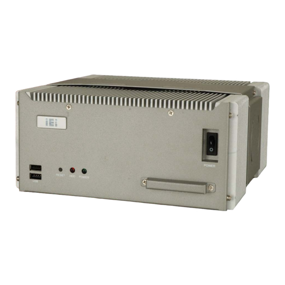
1.1 ECK-161B Embedded System Overview Figure 1-1: ECK-161B Embedded System The ECK-161B is an Intel® Core™ Duo or Intel® Celeron® M based embedded system that is ideal for multimedia applications. The ECK-161B embedded system supports diverse display including one VGA display and one HDTV display. The High Definition (HD) Audio integrated in the ECK-161B provides surround sound quality and supports up to eight channels of sound. -
Page 17: Eck-161B Benefits
7.1 channel HD audio support Six USB 2.0 ports and four serial ports 1.2 ECK-161B Model Variation The ECK-161B embedded system has one preinstalled 1 GB DDR2 SDRAM memory module preinstalled. The model information is listed in Table 1-1 below. ECK-161B... -
Page 18: Technical Specifications
ECK-161B Embedded System 1.3 Technical Specifications The specifications for the Intel based embedded systems are listed below. ECK-161B 1.66 GHz Intel® Core™ Duo T2300E CPU with 2 MB L2 cache 1.86 GHz Intel® Celeron® M 440 CPU with 1 MB L2 cache GMCH: Intel®... -
Page 19: Table 1-2: Technical Specifications
ECK-161B Embedded System 4.1 kg / 6.0 kg Net Weight (NW/GW) 222.20 mm x 210.20 mm x 99.49 mm Dimensions (W x D x H) CE, FCC class A EMC/Safety Table 1-2: Technical Specifications Page 5... -
Page 20: Power Adapter Specifications
ECK-161B Embedded System 1.4 Power Adapter Specifications The ECK-161B series models are shipped with a 150 W power adapter. The specifications for the adapter are listed in Table 1-3: 12.0 V DC Nominal 11.4 V – 12.6 V Regulation 380 mV P-P... -
Page 21: Mechanical Description
ECK-161B Embedded System Chapter Mechanical Description Page 7... -
Page 22: Eck-161B Mechanical Overview
Featuring two GbE, six USB, four serial communication ports, as well as audio, TV-out, and VGA, the ECK-161B offers system integrators and developers the best selection of robust and high performance computing system platforms. -
Page 23: External Overview
ECK-161B Embedded System Figure 2-1: ECK-161B Dimensions (mm) 2.3 External Overview 2.3.1 Front Panel The front panel of the ECK-161B (Figure 2-3) contains following connectors and buttons: 2 x USB 2.0 ports 1 x CompactFlash® slot 1 x Power switch... -
Page 24: Rear Panel Overview
Figure 2-2: ECK-161B Front Panel 2.3.2 Rear Panel Overview The rear panel of the ECK-161B contains all the external I/O interface connectors and power connector. An overview of the rear panel is shown in Figure 2-3 below. Figure 2-3: ECK-161B Rear Panel... -
Page 25: Internal Overview
4 x USB 2.0 ports 1 x VGA connector 2.4 Internal Overview The ECK-161B internal components are listed below: 1 x IEI KINO-9452 motherboard (preinstalled) 1 x 1 GB DDR2 SDRAM DIMM module (preinstalled) 1 x 2.5” SATA HDD (optional) -
Page 26: System Specifications
ECK-161B Embedded System Chapter System Specifications Page 12... -
Page 27: Cpu Support
ECK-161B Embedded System 3.1 CPU Support NOTE: The ECK-161B has a preinstalled 1.66 GHz Intel® Core™ Duo or 1.86GHz Intel® Celeron® M CPU. If the CPU fails, the motherboard has to be replaced. Please contact the IEI reseller or vendor you purchased the ECK-161B from or contact an IEI sales representative directly. -
Page 28: Intel ® Celeron ® M Specifications
ECK-161B Embedded System Embedded lifecycle support protects system investment by enabling extended product availability for embedded and communications customers ® ® 3.1.2 Intel Celeron M Specifications The specifications for the Intel® Celeron® M processor are listed below Intel® Streaming SIMD Extensions accelerates 3D graphics performance, video decoding/encoding, and speech recognition. -
Page 29: Intel Ich7-M Southbridge Chipset
ECK-161B Embedded System 250 MHz core render clock and 200 MHz core display clock at 1.05 V core voltage Supports TV-Out, CRT and SDVO Chip-to-chip interface between (G)MCH and ICH Configurable as x2 or x4 DMI lanes DMI lane reversal support... -
Page 30: Graphics Support
ECK-161B Embedded System 3.3 Graphics Support The graphics features listed below are all integrated on the Intel® 945GM Northbridge chipset. Analog CRT Integrated 400 MHz RAMDAC Analog monitor support up to QXGA Support for CRT hot plug TV-Out Three integrated 10-bit DACS... - Page 31 ECK-161B Embedded System Wake-on-LAN support meeting the ACPI requirements Statistics for SNMP MIB II, Ethernet-like MIB and Ethernet MIB (802.3z, clause 30) Serial EEPROM or serial flash supported JTAG supported 196-FBGA package Page 17...
-
Page 32: Installation
ECK-161B Embedded System Chapter Installation Page 18... -
Page 33: Anti-Static Precautions
Electrostatic discharge (ESD) can cause serious damage to electronic components, including the motherboard and the power module. (Dry climates are especially susceptible to ESD.) It is therefore critical that whenever the ECK-161B is opened and any electrical component handled, the following anti-static precautions are strictly adhered to. -
Page 34: Unpacking
Step 7: 4.2.2 Unpacking After the ECK-161B is received make sure the following components are included in the package. If any of these components are missing, please contact the ECK-161B reseller or vendor where it was purchased or contact an IEI sales representative immediately. -
Page 35: Compactflash® Card Installation
4.2.3 CompactFlash® Card Installation To install the CF card, please follow the steps below. Locate the CF slot on the front panel of the ECK-161B. Step 1: Remove the two CF slot cover retention screws from the front panel (Figure Step 2: 4-1). -
Page 36: Bottom Panel Removal
(Figure 4-4). Figure 4-3: Bottom Panel Retention Screws (Bottom) Figure 4-4: Bottom Panel Retention Screws (Side) Remove the eight bottom panel retention screws. Step 3: Gently remove the bottom panel from the ECK-161B. Step 4: Step 0: Page 22... -
Page 37: Hdd Installation
ECK-161B Embedded System 4.2.5 HDD Installation One 2.5” SATA HDD can be installed in the ECK-161B embedded system. To install the HDD, follow the instructions below. Remove the bottom panel. See Section 4.2.3. Step 1: Remove the two PCI card holder retention screws and remove the PCI card Step 2: holder (Figure 4-5). -
Page 38: Figure 4-6: Hdd Bracket Retention Screws
ECK-161B Embedded System Figure 4-6: HDD Bracket Retention Screws Install the metal plate for securing SATA cable. Align the retention screw Step 4: holes on the metal plate with the two retention screw holes near the connector side on the bottom of the HDD. Insert two retention screws to secure the metal plate with the HDD (Figure 4-7). -
Page 39: Figure 4-8: Hdd Retention Screws
Secure the SATA cable to the HDD. Connect the SATA cable from the Step 6: ECK-161B to the rear of the HDD. Insert two retention screws to secure the SATA cable with the HDD (Figure 4-9). Figure 4-9: SATA Cable Retention Screws... -
Page 40: Pci Expansion Card Installation
Step 0: 4.2.6 PCI Expansion Card Installation The ECK-161B has one PCI slot. The PCI expansion card with a depth under 155 mm can be installed in the ECK-161B. To install the PCI card, follow the instructions below. Remove the bottom panel. See Section 4.2.3. -
Page 41: Figure 4-10: Pci Card Holder Retention Screws
Remove the two PCI card holder retention screws (Figure 4-12) and remove the Step 3: PCI card holder. Figure 4-12: PCI Card Holder Retention Screws Insert the PCI card into the PCI slot in the ECK-161B (Figure 4-13). Step 4: Figure 4-13: PCI Card Installation Page 27... -
Page 42: Eck-161B Series Wall Mounting
Figure 4-14: Secure the PCI Card 4.2.7 ECK-161B Series Wall Mounting To mount the ECK-161B, please follow the steps below. Locate the four ECK-161B series mounting bracket retention screw holes on the Step 1: bottom of the chassis. See Figure 4-15. -
Page 43: Cable Connections
ECK-161B Embedded System Align the round retention screws on the first bracket with the ECK-161B Step 2: retention screw holes on the bottom of the chassis. Insert one of the retention screws into each of the retention holes. Align the round retention screws on the second bracket with the ECK-161B Step 3: series retention screw holes on the other side of the bottom of the chassis. -
Page 44: Power -O N Procedure
Incorrect voltages applied to the system may cause damage to the internal electronic components and may also cause injury to the user. The ECK-161B has two power input connectors shown below, one supports 12 V DC input and the other supports 9 ~ 36 V DC input. -
Page 45: Power-On Procedure
ECK-161B Embedded System 4.3.2 Power-on Procedure To power-on the ECK-161B please follow the steps below: Turn on the power switch (Figure 4-17). Step 6: Once turned on, the green power LED on the front panel should be turned on. Step 7:... - Page 46 For the replacement procedures of the component listed above, please refer to Section 4.2. A user cannot replace some of the components in the ECK-161B. If the following components fail it must be shipped back to IEI to be replaced. Please contact the system vendor, reseller or an IEI sales person directly.
-
Page 47: Ami Bios Setup
ECK-161B Embedded System Chapter AMI BIOS Setup Page 33... -
Page 48: Introduction
ECK-161B Embedded System 5.1 Introduction A licensed copy of AMI BIOS is preprogrammed into the ROM BIOS. The BIOS setup program allows users to modify the basic system configuration. This chapter describes how to access the BIOS setup program and the configuration options that may be changed. -
Page 49: Getting Help
ECK-161B Embedded System F2 /F3 key Change color from total 16 colors. F2 to select color forward. F10 key Save all the CMOS changes, only for Main Menu Table 5-1: BIOS Navigation Keys 5.1.3 Getting Help When F1 is pressed a small help window describing the appropriate keys to use and the possible selections for the highlighted item appears. -
Page 50: Bios Menu 1: Main
ECK-161B Embedded System BIOS Menu 1: Main System Overview The System Overview lists a brief summary of different system components. The fields in System Overview cannot be changed. The items shown in the system overview include: AMI BIOS: Displays auto-detected BIOS information... -
Page 51: Advanced
ECK-161B Embedded System The System Overview field also has two user configurable fields: System Time [xx:xx:xx]: The system time is set here. System Date [Day xx/xx/xxxx]: The system date is set here. 5.3 Advanced The Advanced menu (BIOS Menu 2) allows access to the CPU and peripheral device... -
Page 52: Cpu Configuration
ECK-161B Embedded System BIOS Menu 2: Advanced 5.3.1 CPU Configuration The CPU Configuration menu (BIOS Menu 3) shows detailed CPU specifications and CPU configuration options. Page 38... -
Page 53: Ide Configuration
ECK-161B Embedded System BIOS Menu 3: CPU Configuration The CPU Configuration menu (BIOS Menu 3) lists the following CPU details: Manufacturer: Lists the name of the CPU manufacturer Brand String: Lists the brand name of the CPU being used Frequency: Lists the CPU processing speed... -
Page 54: Bios Menu 4: Ide Configuration
ECK-161B Embedded System BIOS Menu 4: IDE Configuration ATA/IDE Configuration [Compatible] The ATA/IDE Configuration BIOS option allows the user to configure the ATA/IDE device mode. Disable all ATA/IDE ports. No Primary/Secondary IDE Disabled mode is presented for configuration Up to 4 HDDs can be used, two for SATA and the other... -
Page 55: Ide Master, Ide Slave
ECK-161B Embedded System Legacy IDE Channels [SATA Pri, PATA Sec] Use the Legacy IDE Channels option configures PATA and SATA resources for operating systems that require legacy IDE operation. Enable up to two SATA devices SATA Only This option allows the system to access the SATA... -
Page 56: Bios Menu 5: Ide Master And Ide Slave Configuration
ECK-161B Embedded System BIOS Menu 5: IDE Master and IDE Slave Configuration Type [Auto] The Type BIOS option determines the type of device that the AMIBIOS attempts to boot from after the Power-On Self-Test (POST) has completed. Selecting this value prevents the BIOS from searching Not Installed for an IDE disk drive on the specified channel. -
Page 57: Zip
ECK-161B Embedded System IDE disk drives on the specified channel. This option specifies an ATAPI Removable Media ARMD Device. These include, but are not limited to: LS-120 LBA/Large Mode [Auto] The LBA/Large Mode BIOS option disables or auto detects LBA (Logical Block Addressing). -
Page 58: Pio Mode [Auto]
ECK-161B Embedded System PIO Mode [Auto] The PIO Mode option selects the IDE PIO (Programmable I/O) mode program timing cycles between the IDE drive and the programmable IDE controller. As the PIO mode increases, the cycle time decreases. This setting allows the BIOS to auto detect the PIO mode. Use... -
Page 59: Super Io Configuration
ECK-161B Embedded System cannot be determined. Select this value to prevent the BIOS from using the Disabled SMART feature. Select this value to allow the BIOS to use the SMART Enabled feature on support hard disk drives. 32Bit Data Transfer [Enabled] The 32Bit Data Transfer BIOS option enables or disables 32-bit data transfers. -
Page 60: Bios Menu 6: Super Io Configuration
ECK-161B Embedded System BIOS Menu 6: Super IO Configuration Serial Port1 Address [3F8/IRQ4] The Serial Port1 Address option allows BIOS to select the Serial Port 1 base address. No base address is assigned to Serial Port 1 Disabled Serial Port 1 I/O port address is 3F8 and the interrupt... -
Page 61: Hardware Health Configuration
ECK-161B Embedded System No base address is assigned to Serial Port 2 Disabled Serial Port 2 I/O port address is 3F8 and the interrupt 2F8/IRQ3 EFAULT address is IRQ3 Serial Port 2 I/O port address is 3E8 and the interrupt... -
Page 62: Bios Menu 7: Hardware Health Configuration
ECK-161B Embedded System BIOS Menu 7: Hardware Health Configuration CPU FAN Mode Setting: [Full On mode] The CPU FAN Mode Setting has the following options: If selected, there are no additional configurable Full On mode EFAULT options. If selected, the following options will appear with... -
Page 63: Acpi Configuration
ECK-161B Embedded System Slop PWM 1: 0 PWM, 1 PWM (Default), 2 PWM, 4 PWM, 8 PWM, 16 PWM, 32 PWM or 64 PWM If selected, the following option will appear with PWM Manually values that can be configured: mode CPU Fan PWM Control The following system parameters and values are shown. -
Page 64: Bios Menu 8: Acpi Configuration
ECK-161B Embedded System BIOS Menu 8: ACPI Configuration Suspend mode [S3 (STR)] Use the Suspend Mode option to specify the sleep state the system enters when it is not being used. The system enters S1(POS) sleep state. The system S1 (POS) appears off. -
Page 65: Apm Configuration
ECK-161B Embedded System 5.3.6 APM Configuration Use the APM Configuration menu (BIOS Menu 9) to select the advanced power management. BIOS Menu 9: APM Configuration AT/ATX power [ATX power] Use the AT/ATX power BIOS option to select the power supply that is connected to the system. -
Page 66: Resume On Pme# [Disabled]
ECK-161B Embedded System The system remains turned off Power Off EFAULT The system turns on Power On Resume on PME# [Disabled] The Resume on PME# BIOS option specifies if the system will be roused from a suspended or standby state when there is activity on the PCI PME (power management event) controller. -
Page 67: Remote Access Configuration
ECK-161B Embedded System RTC Alarm Date (Days) RTC Alarm Time After setting the alarm, the computer will turn itself on from a suspend state when the alarm goes off. 5.3.7 Remote Access Configuration Use the Remote Access Configuration menu (BIOS Menu 10) to configure remote access parameters. -
Page 68: Usb Configuration
ECK-161B Embedded System Remote Access [Disabled] Use the Remote Access option to enable or disable access to the remote functionalities of the system. Remote access is disabled. Disabled EFAULT Remote access configuration options shown below Enabled appear: Serial Port Number... -
Page 69: Bios Menu 11: Usb Configuration
ECK-161B Embedded System BIOS Menu 11: USB Configuration USB Configuration The USB Configuration field shows the system USB configuration. The items listed are: Module Version: x.xxxxx.xxxxx USB Devices Enabled The USB Devices Enabled field lists the USB devices that are enabled on the system USB Functions [Enabled] Use the USB Functions BIOS option to enable or disable USB function support. -
Page 70: Usb 2.0 Controller [Enabled]
ECK-161B Embedded System USB 2.0 Controller [Enabled] Use the USB 2.0 Controller BIOS option to enable or disable the USB 2.0 controller USB 2.0 controller enabled Enabled EFAULT USB 2.0 controller disabled Disabled Legacy USB Support [Enabled] Use the Legacy USB Support BIOS option to enable USB mouse and USB keyboard support. -
Page 71: Pci/Pnp
ECK-161B Embedded System Systems with OSes that do not support EHCI can Disabled use the EHCI handoff functionality. Systems with OSes that do not support EHCI cannot Enabled EFAULT use the EHCI handoff functionality. 5.4 PCI/PnP Use the PCI/PnP menu (BIOS Menu 12) to configure advanced PCI and PnP settings. -
Page 72: Irq# [Available]
ECK-161B Embedded System IRQ# [Available] Use the IRQ# address to specify what IRQs can be assigned to a particular peripheral device. The specified IRQ is available to be used by Available EFAULT PCI/PnP devices The specified IRQ is reserved for use by Legacy ISA... -
Page 73: Boot
ECK-161B Embedded System DM Channel 1 DM Channel 3 DM Channel 5 DM Channel 6 DM Channel 7 Reserved Memory Size [Disabled] Use the Reserved Memory Size BIOS option to specify the amount of memory that should be reserved for legacy ISA devices. -
Page 74: Boot Settings Configuration
ECK-161B Embedded System BIOS Menu 13: Boot 5.5.1 Boot Settings Configuration Use the Boot Settings Configuration menu (BIOS Menu 14) to configure advanced system boot options. Page 60... -
Page 75: Bios Menu 14: Boot Settings Configuration
ECK-161B Embedded System BIOS Menu 14: Boot Settings Configuration Quick Boot [Enabled] Use the Quick Boot BIOS option to make the computer speed up the boot process. No POST procedures are skipped Disabled Some POST procedures are skipped to decrease... -
Page 76: Addon Rom Display Mode [Force Bios]
ECK-161B Embedded System AddOn ROM Display Mode [Force BIOS] Use the AddOn ROM Display Mode option to allow add-on ROM (read-only memory) messages to be displayed. The system forces third party BIOS to display Force BIOS EFAULT during system boot. -
Page 77: Security
ECK-161B Embedded System Can be booted from a remote system through the Enabled 5.6 Security Use the Security menu (BIOS Menu 15) to set system and user passwords. BIOS Menu 15: Security Change Supervisor Password Use the Change Supervisor Password to set or change a supervisor password. The default for this option is Not Installed. -
Page 78: Chipset
ECK-161B Embedded System Change User Password Use the Change User Password to set or change a user password. The default for this option is Not Installed. If a user password must be installed, select this field and enter the password. After the password has been added, Install appears next to Change User Password. -
Page 79: North Bridge Configuration
ECK-161B Embedded System BIOS Menu 16: Chipset 5.7.1 North Bridge Configuration Use the North Bridge Configuration menu (BIOS Menu 17) to configure the northbridge chipset. Page 65... -
Page 80: Bios Menu 17: North Bridge Chipset Configuration
ECK-161B Embedded System BIOS Menu 17: North Bridge Chipset Configuration Memory Hole [Disabled] Use the Memory Hole option to reserve memory space between 15MB and 16MB for ISA expansion cards that require a specified area of memory to work properly. If an older ISA expansion card is used, please refer to the documentation that came with the card to see if it is necessary to reserve the space. -
Page 81: Internal Graphics Mode Select [Enable, 8Mb]
ECK-161B Embedded System PCI/IGD EFAULT Internal Graphics Mode Select [Enable, 8MB] Use the Internal Graphic Mode Select option to specify the amount of system memory that can be used by the Internal graphics device. Disable 1MB of memory used by internal graphics device... -
Page 82: Boot Display Device [Auto]
ECK-161B Embedded System selected, the maximum amount of graphics memory is 128MB. Configuration options are listed below. 64MB 128MB EFAULT Maximum DVMT Boot Display Device [Auto] Use the Boot Display Device option to select the display device used by the system when it boots. -
Page 83: South Bridge Configuration
ECK-161B Embedded System 2048*1536 (36bits) Local Flat Panel Scaling [Auto] Use the Local Flat Panel Scaling option to select the method of scaling for the flat panel screen attached to the system. Scaling is automatic Auto EFAULT Scaling is forced... -
Page 84: Bios Menu 18:South Bridge Chipset Configuration
ECK-161B Embedded System BIOS Menu 18:South Bridge Chipset Configuration ASF Support [Enabled] Use the ASF Support BIOS option to control the system’s ability to connect to a remote management server. The Alert Standard Format (ASF) controller is activated Enabled EFAULT and can communicate with a remote management server. -
Page 85: Exit
ECK-161B Embedded System The onboard High Definition Audio controller is disabled Disabled OnBoard LAN1 (BCM5787M) [Enabled] The OnBoard LAN1 (BCM5787M) option enables or disables the onboard LAN1. Onboard LAN1 controller manually disabled Disabled The onboard LAN1 controller automatically detected and... -
Page 86: Bios Menu 19:Exit
ECK-161B Embedded System BIOS Menu 19:Exit Save Changes and Exit Use the Save Changes and Exit option to save the changes made to the BIOS options and to exit the BIOS configuration setup program. Discard Changes and Exit Use the Discard Changes and Exit option to exit the BIOS configuration setup program without saving the changes made to the system. -
Page 87: Load Optimal Defaults
ECK-161B Embedded System Load Optimal Defaults Use the Load Optimal Defaults option to load the optimal default values for each of the parameters on the Setup menus. F9 key can be used for this operation. Load Failsafe Defaults Use the Load Failsafe Defaults option to load failsafe default values for each of the parameters on the Setup menus. -
Page 88: Driver Installation
ECK-161B Embedded System Chapter Driver Installation Page 74... -
Page 89: Available Software Drivers
6.2 Chipset Driver Installation To install the chipset driver, please follow the steps below: Insert the CD into the system that contains the ECK-161B embedded system. Step 1: Open the 1-INF directory and locate the icon for the infinst_autol.exe installation file. -
Page 90: Figure 6-1: Installshield Wizard Preparation Screen
ECK-161B Embedded System Figure 6-1: InstallShield Wizard Preparation Screen The “Welcome” window in Figure 6-2 appears next. Step 3: Figure 6-2: Welcome Screen Click “N ” and the license agreement shown in Figure 6-3 appears. Step 4: Page 76... -
Page 91: Figure 6-3: License Agreement
ECK-161B Embedded System Figure 6-3: License Agreement Agree to the license terms by clicking “Y ”. The “Readme” in Figure 6-4 Step 5: appears. Figure 6-4: Readme Information Click “Y ”. The driver is installed on the computer. After the installation is Step 6: complete, the installation complete screen shown in Figure 6-5 appears. -
Page 92: Vga Driver
ECK-161B Embedded System the preferred option and click “F ” to complete the installation process. INISH Step 0: Figure 6-5: Restart the Computer 6.3 VGA Driver To install the VGA driver, please follow the steps below: Insert the Utility CD that came with the motherboard into the system CD drive. -
Page 93: Figure 6-6: Starting Install Shield Wizard Screen
ECK-161B Embedded System Figure 6-6: Starting Install Shield Wizard Screen The Preparing Setup window appears next (Figure 6-7). Step 4: Figure 6-7: Preparing Setup Screen Page 79... -
Page 94: Figure 6-8: Vga Driver Installation Welcome Screen
ECK-161B Embedded System A Welcome screen shown in Figure 6-8 appears. Click N to continue the Step 5: installation. Figure 6-8: VGA Driver Installation Welcome Screen A license agreement shown in Figure 6-9 appears. Read through the license Step 6: agreement. -
Page 95: Figure 6-10: Vga Driver Installing Notice
ECK-161B Embedded System the “Y ” button (Figure 6-9). The installation notice shown in Figure 6-10 appears. Figure 6-10: VGA Driver Installing Notice After the driver installation process is complete, a confirmation screen shown in Step 8: Figure 6-11 appears. -
Page 96: Broadcom Lan Driver (For Gbe Lan) Installation
ECK-161B Embedded System 6.4 Broadcom LAN Driver (for GbE LAN) Installation To install the Broadcom LAN driver, please follow the steps below. Open Windows Control Panel (Figure 6-12). Step 1: Figure 6-12: Access Windows Control Panel Double click the System icon (Figure 6-13). -
Page 97: Figure 6-13: Double Click The System Icon
ECK-161B Embedded System Figure 6-13: Double Click the System Icon Double click the Device Manager tab (Figure 6-14). Step 3: Figure 6-14: Double Click the Device Manager Tab A list of system hardware devices appears (Figure 6-15). Step 4: Page 83... -
Page 98: Figure 6-15: Device Manager List
ECK-161B Embedded System Figure 6-15: Device Manager List Double click the listed device that has question marks next to it. (This means Step 5: Windows does not recognize the device). The Device Driver Wizard appears (Figure 6-16). Click N to continue. -
Page 99: Figure 6-17: Locate Driver Files
ECK-161B Embedded System Select “Specify a Location” in the Locate Driver Files window (Figure 6-17). Step 7: Click N to continue. Figure 6-17: Locate Driver Files Select the proper OS folder under the “X:\3-LAN\BROADCOM BCM57xx Step 8: Drivers” directory (Figure 6-18) in the location browsing window, where “X:\” is the system CD drive. -
Page 100: Realtek Hd Audio Driver (Alc883) Installation
ECK-161B Embedded System Click OK to continue. A driver files location menu window appears. Click N Step 9: continue. The driver is installed.Step 0: 6.5 RealTek HD Audio Driver (ALC883) Installation To install the Realtek High Definition (HD) Audio driver, please follow the steps below. -
Page 101: Figure 6-20: Double Click The System Icon
ECK-161B Embedded System Figure 6-20: Double Click the System Icon Double click the Device Manager tab (Figure 6-14). Step 3: Figure 6-21: Double Click the Device Manager Tab Page 87... -
Page 102: Figure 6-22: Device Manager List
ECK-161B Embedded System A list of system hardware devices appears (Figure 6-15). Step 4: Figure 6-22: Device Manager List Double click the listed device that has question marks next to it. (This means Step 5: Windows does not recognize the device). -
Page 103: Figure 6-23: Search For Suitable Driver
ECK-161B Embedded System Figure 6-23: Search for Suitable Driver Select “Specify a Location” in the Locate Driver Files window (Figure 6-17). Step 7: Click N to continue. Page 89... -
Page 104: Intel Matrix Storage Manager Installation
ECK-161B Embedded System Figure 6-24: Locate Driver Files Select “X:\4-AUDIO\AC-KIT883HD\WIN” directory in the location browsing Step 8: window, where “X:\” is the system CD drive (Figure 6-18). Click OK to continue. The driver is installed. Step 9: Step 0: The confirmation screen offers the option of restarting the computer now or later. -
Page 105: Figure 6-25: Preparing Setup Screen
ECK-161B Embedded System installation file. The Preparing Setup window appears (). Step 3: Figure 6-25: Preparing Setup Screen A Welcome screen appears. Click N to continue the installation. Step 4: A license agreement appears. Read through the license agreement. Step 5: The “Uninstallation Warning”... - Page 106 ECK-161B Embedded System After the driver installation process is complete, a confirmation screen appears. Step 10: The confirmation screen allows user to restart the computer immediately after Step 11: the installation is complete or to restart the computer later. For the settings to take effect the computer must be restarted.
-
Page 107: Asafety Precautions
ECK-161B Embedded System Appendix Safety Precautions Page 93... -
Page 108: Safety Precautions
Do not apply voltage levels that exceed the specified voltage range. Doing so may cause fire and/or an electrical shock. Electric shocks can occur if the ECK-161B chassis is opened when the ECK-161B is running. Do not drop or insert any objects into the ventilation openings of the ECK-161B. -
Page 109: Anti-Static Precautions
When maintaining or cleaning the ECK-161B, please follow the guidelines below. A.2.1 Maintenance and Cleaning Prior to cleaning any part or component of the ECK-161B, please read the details below. Except for the LCD panel, never spray or squirt liquids directly onto any other components. -
Page 110: Cleaning Tools
In such case, the product will be explicitly mentioned in the cleaning tips. Below is a list of items to use when cleaning the ECK-161B. C loth – Although paper towels or tissues can be used, a soft, clean piece of cloth is recommended when cleaning the ECK-161B. -
Page 111: Biei Embedded System Series
ECK-161B Embedded System Appendix IEI Embedded System Series Page 97... -
Page 112: Iei Embedded System Series
ECK-161B Embedded System B.1 IEI Embedded System Series B.1.1 Overview IEI embedded industrial PC systems are ideal for manufacturing and automation environments where heavy processing demands exist. These systems are designed to operate effectively within high-stress environments that have diverse operational conditions. -
Page 113: Iei Embedded System Series Variations
ECK-161B Embedded System B.1.3 IEI Embedded System Series Variations The differences between the series are listed below. Motherboard Cooling CompactFlash Drive Bays ECW-180A WAFER Two cooling fans One CF slot None ECW-180B WAFER Fanless One CF slot None ECW-181A WAFER... -
Page 114: Amd ® Geode
ECK-161B Embedded System Model Number System Chipset DC Input Drive Bays ® ECW-180AS1 CS5536 None ® ECW-180AS1WD CS5536 9V ~ 36V None ® ECW-180BS1 CS5536 None None ECW-180BS1WD ® CS5536 9V ~ 36V None None ® ECW-181AS1 CS5536 Two 2.5” HDD ®... -
Page 115: Via Mark 800Mhz Solutions
ECK-161B Embedded System Model Number System Chipset DC Input Drive Bays ECW-180AS3 ® VT8237R+ None ECW-180AS3WD ® VT8237R+ 9V ~ 36V None ® ECW-180BS3 VT8237R+ None None ® ECW-180BS3WD VT8237R+ 9V ~ 36V None None ECW-181AS3 ® VT8237R+ Two 2.5” HDD ®... -
Page 116: Intel Celeron M 1 Ghz Solutions
ECK-161B Embedded System Model Number System Chipset DC Input Drive Bays ® IBX-520CX CX700M None One SATA drive supported ® ® Table B-6: VIA MARK Embedded System Solutions ® ® B.2.6 Intel Celeron M 1 GHz Solutions ® ® The model listed in the table below support an Intel Celeron M 1 GHz zero cache CPU. -
Page 117: Intel Pentium M 1.6Ghz Solutions
ECK-161B Embedded System Model Number System Chipset DC Input Drive Bays (optional) ® ® Table B-8: Intel Celeron M 1.5GHz Solutions ® ® B.2.8 Intel Pentium M 1.6GHz Solutions ® ® All the models listed in the table below support an Intel Pentium M 1.6GHz CPU. -
Page 118: Lga 775 Intel ® Pentium
ECK-161B Embedded System ® ® ® B.2.10 LGA 775 Intel Pentium 4/ Pentium D Solutions ® ® ® All the models listed in the table below support a LGA 775 Intel Pentium 4/ Pentium CPU. Model Number System Chipset DC Input... -
Page 119: Cbios Menu Options
ECK-161B Embedded System Appendix BIOS Menu Options Page 105... -
Page 120: Bios Configuration Options
ECK-161B Embedded System C.1 BIOS Configuration Options Below is a list of BIOS configuration options described in Chapter 5. System Overview ....................36 ATA/IDE Configuration [Compatible]..............40 Legacy IDE Channels [SATA Pri, PATA Sec]............41 IDE Master and IDE Slave ..................41 ... - Page 121 ECK-161B Embedded System Resume on PME# [Disabled] ................52 Resume On PCI-Express WAKE# [Enabled] ............52 Resume On RTC Alarm [Disabled]...............52 RTC Alarm Date (Days) ..................53 RTC Alarm Time .....................53 Remote Access [Disabled]..................54 Serial Port Number ....................54 ...
- Page 122 ECK-161B Embedded System Internal Graphics Mode Select [Enable, 8MB] ............67 DVMT Mode Select [DVMT Mode].................67 DVMT/FIXED Memory [128MB] ................67 Boot Display Device [Auto]...................68 Flat Panel Type [1024*768]..................68 Local Flat Panel Scaling [Auto] ................69 TV Standard [VBIOS-Default]................69 ...
-
Page 123: Dwatchdog Timer
ECK-161B Embedded System Appendix Watchdog Timer Page 109... - Page 124 ECK-161B Embedded System NOTE: The following discussion applies to DOS environment. IEI support is contacted or the IEI website visited for specific drivers for more sophisticated operating systems, e.g., Windows and Linux. The Watchdog Timer is provided to ensure that standalone systems can always recover from catastrophic conditions that cause the CPU to crash.
-
Page 125: Example Program
ECK-161B Embedded System NOTE: When exiting a program it is necessary to disable the Watchdog Timer, otherwise the system resets. Example program: ; INITIAL TIMER PERIOD COUNTER W_LOOP: AX, 6F02H ;setting the time-out value BL, 30 ;time-out value is 48 seconds ;... -
Page 126: Eaddress Mapping
ECK-161B Embedded System Appendix Address Mapping Page 112... -
Page 127: Io Address Map
ECK-161B Embedded System E.1 IO Address Map I/O address Description Range 000-01F DMA Controller 020-021 Interrupt Controller 040-043 System time 060-06F Keyboard Controller 070-07F System CMOS/Real time Clock 080-09F DMA Controller 0A0-0A1 Interrupt Controller 0C0-0DF DMA Controller 0F0-0FF Numeric data processor... -
Page 128: St Mb Memory Address Map
ECK-161B Embedded System E.2 1st MB Memory Address Map Memory address Description 00000-9FFFF System memory A0000-BFFFF VGA buffer F0000-FFFFF System BIOS 1000000- Extend BIOS Table E-2: 1 MB Memory Address Map E.3 IRQ Mapping Table IRQ0 System Timer IRQ8 RTC clock... -
Page 129: Hazardous Materials Disclosure
ECK-161B Embedded System Appendix Hazardous Materials Disclosure Page 115... -
Page 130: Hazardous Material Disclosure Table For Ipb Products Certified As Rohs Compliant Under 2002/95/Ec Without Mercury
ECK-161B Embedded System F.1 Hazardous Material Disclosure Table for IPB Products Certified as RoHS Compliant Under 2002/95/EC Without Mercury The details provided in this appendix are to ensure that the product is compliant with the Peoples Republic of China (China) RoHS standards. The table below acknowledges the presences of small quantities of certain materials in the product, and is applicable to China RoHS only. - Page 131 ECK-161B Embedded System Part Name Toxic or Hazardous Substances and Elements Lead Mercury Cadmium Hexavalent Polybrominated Polybrominated (Hg) (Cd) Chromium (Pb) Biphenyls Diphenyl Ethers (CR(VI)) (PBB) (PBDE) Housing Display Printed Circuit Board Metal Fasteners Cable Assembly Fan Assembly Power Supply...
- Page 132 ECK-161B Embedded System 此附件旨在确保本产品符合中国 RoHS 标准。以下表格标示此产品中某有毒物质的含量符 合中国 RoHS 标准规定的限量要求。 本产品上会附有”环境友好使用期限”的标签,此期限是估算这些物质”不会有泄漏或突变”的 年限。本产品可能包含有较短的环境友好使用期限的可替换元件,像是电池或灯管,这些 元件将会单独标示出来。 部件名称 有毒有害物质或元素 铅 汞 镉 六价铬 多溴联苯 多溴二苯醚 (Pb) (Hg) (Cd) (CR(VI)) (PBB) (PBDE) 壳体 显示 印刷电路板 金属螺帽 电缆组装 风扇组装 电力供应组装 电池 O: 表示该有毒有害物质在该部件所有物质材料中的含量均在 SJ/T11363-2006 标准规定的限量要求以下。 X: 表示该有毒有害物质至少在该部件的某一均质材料中的含量超出 SJ/T11363-2006 标准规定的限量要求。...
-
Page 133: Index
ECK-161B Embedded System Index Page 119... - Page 134 ECK-161B Embedded System A I Advanced Power Management ....70 I/O interface connectors, external....10 ALC883..........75, 86 ICH7-M..........14, 15 AMI BIOS..........34, 36 Installation Checklist ........30 anti-static precautions Intel 945GM ........14, 16 anti-static pad ........95 anti-static wristband ......95 L...
- Page 135 ECK-161B Embedded System TV-Out..........15, 16 S Safety Precautions........94 U SATA HDD ........2, 11, 23 unpacking...........20 SDVO...........15, 16 USB 2.0..........15, 56 SuperIO .............37 W T Wall Mounting ..........28 TV-out ........2, 4, 8, 11, 30 Page 121...
Need help?
Do you have a question about the ECK-161B and is the answer not in the manual?
Questions and answers