Table of Contents
Advertisement
Quick Links
ECN-360A-ULT3 Em b e d d e d S ys te m
MODEL:
ECN-360A-ULT3
Hig h P e rfo rm a n c e Fa n le s s Em b e d d e d S ys te m with In te l® Co re ™ i5-6300U/
Ce le ro n ® 3855U p ro c e s s o r, Du a l HDMI, RS -232/422/485,
US B 3.0, Ro HS Co m p lia n t
Us e r Ma n u a l
P a g e i
Re v. 1.00 – 6 No ve m b e r 2017
Advertisement
Table of Contents

Related Manuals for IEI Technology ECN-360A-ULT3


Summary of Contents for IEI Technology ECN-360A-ULT3
- Page 1 ECN-360A-ULT3 Em b e d d e d S ys te m MODEL: ECN-360A-ULT3 Hig h P e rfo rm a n c e Fa n le s s Em b e d d e d S ys te m with In te l® Co re ™ i5-6300U/ Ce le ro n ®...
- Page 2 ECN-360A-ULT3 Em b e d d e d S ys te m Re vis io n Date Version Changes 6 November, 2017 1.00 Initial release P a g e ii...
- Page 3 ECN-360A-ULT3 Em b e d d e d S ys te m Co p yrig h t COP YRIGHT NOTICE The information in this document is subject to change without prior notice in order to improve reliability, design and function and does not represent a commitment on the part of the manufacturer.
- Page 4 ECN-360A-ULT3 Em b e d d e d S ys te m Ma n u a l Co n ve n tio n s WARNING Warnings appear where overlooked details may cause damage to the equipment or result in personal injury. Warnings should be taken seriously.
-
Page 5: Table Of Contents
ECN-360A-ULT3 Em b e d d e d S ys te m Ta b le o f Co n te n ts 1 INTRODUCTION ......................1 1.1 O ........................2 VERVIEW 1.2 M ..................... 2 ODEL ARIATIONS 1.3 F ........................3 EATURES 1.4 T... - Page 6 ECN-360A-ULT3 Em b e d d e d S ys te m 4.2.5 Digital I/O Connector ..................27 4.2.6 Fan Connectors ....................28 4.2.7 Front Panel Connector ..................29 4.2.8 Internal DisplayPort Connector ..............30 4.2.9 Keyboard and Mouse Connector ..............31 4.2.10 LVDS Backlight Inverter Connector ..............
- Page 7 ECN-360A-ULT3 Em b e d d e d S ys te m 5 BIOS ..........................60 5.1 I ......................61 NTRODUCTION 5.1.1 Starting Setup ....................61 5.1.2 Using Setup ...................... 61 5.1.3 Getting Help ..................... 62 5.1.4 Unable to Reboot after Configuration Changes ..........62 5.1.5 BIOS Menu Bar ....................
- Page 8 ECN-360A-ULT3 Em b e d d e d S ys te m B SAFETY PRECAUTIONS ..................106 B.1 S ..................... 107 AFETY RECAUTIONS B.1.1 General Safety Precautions ................107 B.1.2 Anti-static Precautions .................. 107 B.1.3 Product Disposal ................... 108 B.2 M ............
- Page 9 ECN-360A-ULT3 Em b e d d e d S ys te m Lis t o f Fig u re s Figure 1-1: ECN-360A-ULT3 ......................2 Figure 1-2: ECN-360A-ULT3 Front Panel ..................5 Figure 1-3: ECN-360A-ULT3 Rear Panel ..................6 Figure 1-4: Physical Dimensions (mm) ..................7 Figure 3-1: Unscrew the Cover ....................14...
- Page 10 ECN-360A-ULT3 Em b e d d e d S ys te m Figure 4-20: RS-232/422/485 Connector Location ..............42 Figure 4-21: SATA 6Gb/s Drive Connectors Locations ............43 Figure 4-22: SATA Power Connector Locations ...............44 Figure 4-23: SMBus Connector Location ...................45 Figure 4-24: SIM Card Slot Location ...................46 Figure 4-25: SPI Flash Connector Location ................47...
- Page 11 ECN-360A-ULT3 Em b e d d e d S ys te m Lis t o f Ta b le s Table 1-1: ECN-360A-ULT3 Model Variations ................2 Table 1-2: Technical Specifications ....................5 Table 4-1: Peripheral Interface Connectors ................21 Table 4-2: Rear Panel Connectors ....................22 Table 4-3: +12V DC-IN Power Connector Pinouts ..............23...
- Page 12 ECN-360A-ULT3 Em b e d d e d S ys te m Table 4-30: USB 3.0 Port Pinouts ....................53 Table 4-31: AT/ATX Mode Select Switch Settings ..............54 Table 4-32: Flash Descriptor Security Override Jumper Settings ...........55 Table 4-33: HDMI/DP Select Switch Settings ................57 Table 4-34: LVDS Panel Resolution Selection ................58...
- Page 13 ECN-360A-ULT3 Em b e d d e d S ys te m Lis t o f BIOS Me n u s BIOS Menu 1: Main ........................63 BIOS Menu 2: Advanced ......................64 BIOS Menu 3: ACPI Settings .......................65 BIOS Menu 4: AMT Configuration ....................66 BIOS Menu 5: F81866 Super IO Configuration ................67...
-
Page 14: Introduction
ECN-360A-ULT3 Em b e d d e d S ys te m Ch a p te r In tro d u c tio n P a g e 1... -
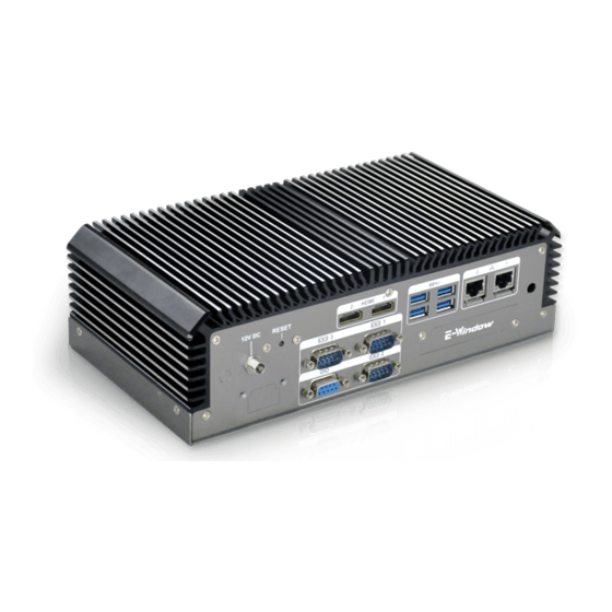
Page 15: Overview
ECN-360A-ULT3 Em b e d d e d S ys te m 1.1 Ove rvie w Figure 1-1: ECN-360A-ULT3 The ECN-360A-ULT3 is a platform based on Intel® Core™ i5-6300U or Intel® Celeron® 3855U processor. The ECN-360A-ULT3 contains two HDMI video outputs, which can be applied to multi-display application and support high Full HD video quality. -
Page 16: Features
ECN-360A-ULT3 Em b e d d e d S ys te m 1.3 Fe a tu re s The ECN-360A-ULT3 features are listed below: On-board CPU » i5-6300U dual-core up to 3.0GHz » 3855U dual-core up to 1.6GHz ... - Page 17 ECN-360A-ULT3 Em b e d d e d S ys te m S p e c ific a tio n s I/O In te rfa c e s 4 x USB 3.0 ports US B 2 x RJ-45 Eth e rn e t LAN1: Intel®...
-
Page 18: Front Panel
ECN-360A-ULT3 Em b e d d e d S ys te m S p e c ific a tio n s Op e ra tin g Vib ra tio n MIL-STD-810F 514.5C-2 (SSD) 2.2 kg/3 kg We ig h t (Ne t/Gro s s ) Table 1-2: Technical Specifications 1.5 Fro n t P a n e l... -
Page 19: Figure 1-3: Ecn-360A-Ult3 Rear Panel
ECN-360A-ULT3 Em b e d d e d S ys te m 1 x E-Window 2 x HDMI ports 4 x USB 3.0 ports 1 x Reset button 2 x RJ-45 LAN ports 2 x RS-232 serial ports ... -
Page 20: Dimensions
ECN-360A-ULT3 Em b e d d e d S ys te m 1.7 Dim e n s io n s The physical dimensions are shown below: Figure 1-4: Physical Dimensions (mm) P a g e 7... -
Page 21: Unpacking
ECN-360A-ULT3 Em b e d d e d S ys te m Ch a p te r Un p a c kin g P a g e 8... -
Page 22: Anti - Static Precautions
ECN-360A-ULT3 Em b e d d e d S ys te m 2.1 An ti-s ta tic P re c a u tio n s WARNING: Failure to take ESD precautions during installation may result in permanent damage to the ECN-360A-ULT3 and severe injury to the user. -
Page 23: Npacking Checklist
ECN-360A-ULT3 Em b e d d e d S ys te m 2.3 1Un pa c kin g Ch e c klis t NOTE: If some of the components listed in the checklist below are missing, please do not proceed with the installation. Contact the IEI reseller or vendor you purchased the ECN-360A-ULT3 from or contact an IEI sales representative directly. - Page 24 ECN-360A-ULT3 Em b e d d e d S ys te m Op tio n a l FSP060-DIBAN2, 12V 60W AC/DC Adapter (P/N: 63040-010060-120-RS) PCIe mini card supports 1-port GbE with REALTEK RTL8111E controller, with PMS 194C I/O bracket and...
-
Page 25: Installation
ECN-360A-ULT3 Em b e d d e d S ys te m Ch a p te r In s ta lla tio n P a g e 12... -
Page 26: Installation Precautions
Electric shock and personal injury might occur if the rear panel of the ECN-360A-ULT3 is opened while the power cord is still connected to an electrical outlet. -
Page 27: Figure 3-1: Unscrew The Cover
ECN-360A-ULT3 Em b e d d e d S ys te m Figure 3-1: Unscrew the Cover Unplug the SATA signal and power cables connected to the ECN-360A-ULT3, S te p 2: and then put the cover on a flat surface (Figure 3-2). -
Page 28: So-Dimm Installation
ECN-360A-ULT3 Em b e d d e d S ys te m Figure 3-3: HDD Installation S te p 4: Reconnect the SATA signal and power cables to the ECN-360A-ULT3. S te p 5: Reinstall the cover. 3.3 S O-DIMM In s ta lla tio n... -
Page 29: Figure 3-4: So-Dimm Socket
ECN-360A-ULT3 Em b e d d e d S ys te m Figure 3-4: SO-DIMM Socket Align the SO-DIMM with the socket. The SO-DIMM must be oriented in such a S te p 3: way that the notch in the middle of the SO-DIMM must be aligned with the plastic bridge in the socket (Figure 3-5). -
Page 30: Mounting The System With Mounting Brackets
ECN-360A-ULT3 Em b e d d e d S ys te m S te p 7: Reinstall the cover that was previously removed in the same position it was before. 3.4 Mo u n tin g th e S ys te m with Mo u n tin g Bra c ke ts To mount the embedded system onto a wall or some other surface using the two mounting brackets, please follow the steps below. -
Page 31: Powering O N /Off The System
ECN-360A-ULT3 Em b e d d e d S ys te m 3.5 P owe rin g On /Off th e S ys te m WARNING: Make sure a power supply with the correct input voltage is being fed into the system. -
Page 32: System Motherboard
ECN-360A-ULT3 Em b e d d e d S ys te m Ch a p te r S ys te m Mo th e rb o a rd P a g e 19... -
Page 33: Peripheral Interface Connectors
ECN-360A-ULT3 Em b e d d e d S ys te m 4.1 P e rip h e ra l In te rfa c e Co n n e c to rs This chapter details all the jumpers and connectors. -
Page 34: Table 4-1: Peripheral Interface Connectors
ECN-360A-ULT3 Em b e d d e d S ys te m Digital I/O connector 10-pin header DIO1 Debug card connector 12-pin wafer DBG_PORT1 Fan connector, CPU 4-pin wafer CPU/FAN1 Fan connector, system 4-pin wafer SYS/FAN1 Front panel connector 6-pin wafer... -
Page 35: External Interface Panel Connectors
ECN-360A-ULT3 Em b e d d e d S ys te m 4.1.3 Exte rn a l In te rfa c e P a n e l Co n n e c to rs The table below lists the connectors on the external I/O panel. -
Page 36: Dc-In Power Connector
ECN-360A-ULT3 Em b e d d e d S ys te m 4.2 In te rn a l P e rip h e ra l Co n n e c to rs The section describes all of the connectors on the ECN-360A-ULT3. -
Page 37: Figure 4-3: Audio Connector Location
ECN-360A-ULT3 Em b e d d e d S ys te m CN Typ e : 10-pin header, p=2.00 mm CN Lo c a tio n : See Figure 4-3 See Table 4-4 CN P in o u ts : The audio connector is connected to external audio devices including speakers and microphones for the input and output of audio signals to and from the system. -
Page 38: Battery Connector
ECN-360A-ULT3 Em b e d d e d S ys te m 4.2.3 Ba tte ry Co n n e c to r CAUTION: Risk of explosion if battery is replaced by an incorrect type. Only certified engineers should replace the on-board battery. -
Page 39: Figure 4-5: Buzzer Connector Location
ECN-360A-ULT3 Em b e d d e d S ys te m Description VBAT+ Table 4-5: Battery Connector Pinouts 4.2.4 Bu zze r Co n n e c to r CN La b e l: 2-pin wafer, p=1.25 mm CN Typ e :... -
Page 40: Digital I/O Connector
ECN-360A-ULT3 Em b e d d e d S ys te m 4.2.5 Dig ita l I/O Co n n e c to r CN La b e l: DIO1 10-pin header, p=2.00 mm CN Typ e : CN Lo c a tio n :... -
Page 41: Figure 4-7: Fan Connector Locations
ECN-360A-ULT3 Em b e d d e d S ys te m 4.2.6 Fa n Co n n e c to rs CN La b e l: CP U/FAN1, S YS /FAN1 4-pin wafer, p=2.54 mm CN Typ e :... -
Page 42: Front Panel Connector
ECN-360A-ULT3 Em b e d d e d S ys te m 4.2.7 Fro n t P a n e l Co n n e c to r CN La b e l: CN11 6-pin wafer, p=2.00 mm CN Typ e :... -
Page 43: Internal Displayport Connector
ECN-360A-ULT3 Em b e d d e d S ys te m 4.2.8 In te rn a l Dis p la yP o rt Co n n e c to r NOTE: The iDP connector is disabled by default since the iDP connector is co-lay with the HDMI1 connector. -
Page 44: Keyboard And Mouse Connector
ECN-360A-ULT3 Em b e d d e d S ys te m Description Description AUX+ AUX- Lane2+ Lane3+ Lane2- Lane3- Lane0+ Lane1+ Lane0- Lane1- VCC3 VCC5 Table 4-10: Internal DisplayPort Connector Pinouts 4.2.9 Ke yb o a rd a n d Mo u s e Co n n e c to r... -
Page 45: Lvds Backlight Inverter Connector
ECN-360A-ULT3 Em b e d d e d S ys te m Description VCC5V Mouse Data Mouse Clock Keyboard Data Keyboard Clock Table 4-11: Keyboard and Mouse Connector Pinouts 4.2.10 LVDS Ba c klig h t In ve rte r Co n n e c to r... -
Page 46: Lvds Lcd Connector
ECN-360A-ULT3 Em b e d d e d S ys te m 4.2.11 LVDS LCD Co n n e c to r CN La b e l: 30-pin crimp, p=1.25 mm CN Typ e : CN Lo c a tio n :... -
Page 47: Lan Led Connectors
ECN-360A-ULT3 Em b e d d e d S ys te m Description Description +LCD VCC +LCD VCC +LCD VCC +LCD VCC Table 4-13: LVDS Connector Pinouts 4.2.12 LAN LED Co n n e c to rs CN La b e l: J P 1, J P 2 2-pin header, p=2.00 mm... -
Page 48: Pcie Mini Card Slot, Full-Size
ECN-360A-ULT3 Em b e d d e d S ys te m 4.2.13 P CIe Min i Ca rd S lo t, Fu ll-s ize CN La b e l: Full-size PCIe Mini card slot CN Typ e : CN Lo c a tio n :... -
Page 49: Table 4-15: Full-Size Pcie Mini Card Slot Pinouts
ECN-360A-ULT3 Em b e d d e d S ys te m Description Description PCIE_WAKE# VCC3 1.5 V VCC3 SIM_VCC SIM_IO CLK- SIM_CLK CLK+ SIM_RST SIM_VPP BUF_PLT_RST# VCC3 BUF_PLT_RST# SATA_RXN2_C VCC3 SATA_RXP2_C 1.5 V SMBCLK SATA_TXN2 SMBDATA SATA_TXP2 USB7- USB7+... -
Page 50: Pcie Mini Card Slot, Half-Size
ECN-360A-ULT3 Em b e d d e d S ys te m 4.2.14 P CIe Min i Ca rd S lo t, Ha lf-s ize CN La b e l: Half-size PCIe Mini card slot CN Typ e : CN Lo c a tio n :... -
Page 51: Power Button
ECN-360A-ULT3 Em b e d d e d S ys te m Description Description BUF_PLT_RST# VCC3 BUF_PLT_RST# PCIE_RX4DN VCC3 PCIE_RX4DP 1.5V SMBCLK PCIE_TX4DN SMBDATA PCIE_TX4DP USBD8- USBD8+ VCC3 VCC3 RF_LINK# BLUELED# 1.5 V VCC3 Table 4-16: Half-size PCIe Mini Slot Pinouts 4.2.15 P owe r Bu tto n... -
Page 52: Power Button Connector
ECN-360A-ULT3 Em b e d d e d S ys te m Figure 4-16: Power Button Location 4.2.16 P owe r Bu tto n Co n n e c to r CN La b e l: P WR_BTN1 2-pin wafer, p=2.00 mm... -
Page 53: Reset Button Connector
ECN-360A-ULT3 Em b e d d e d S ys te m 4.2.17 Re s e t Bu tto n Co n n e c to r CN La b e l: RS T_BTN1 2-pin wafer, p=2.00 mm CN Typ e :... -
Page 54: Serial Port Connectors
ECN-360A-ULT3 Em b e d d e d S ys te m 4.2.18 RS -232 S e ria l P o rt Co n n e c to rs CN La b e l: COM1, COM2 10-pin header, p=2.00 mm... -
Page 55: Rs-232/422/485 Serial Port Connector
ECN-360A-ULT3 Em b e d d e d S ys te m 4.2.19 RS -232/422/485 S e ria l P o rt Co n n e c to r CN La b e l: COM3 10-pin header, p=2.00 mm CN Typ e :... -
Page 56: Sata 6Gb/S Drive Connectors
ECN-360A-ULT3 Em b e d d e d S ys te m Use the optional RS-422/485 cable to connect to a serial device. The pinouts of the DB-9 connector are listed below. RS-422 Pinouts RS-485 Pinouts Table 4-21: DB-9 RS-422/485 Pinouts 4.2.20 S ATA 6Gb /s Drive Co n n e c to rs... -
Page 57: Sata Power Connectors
ECN-360A-ULT3 Em b e d d e d S ys te m 4.2.21 S ATA P o we r Co n n e c to rs SATA_PWR1, SATA_PWR2 CN La b e l: 2-pin wafer, p=2.00 mm CN Typ e :... -
Page 58: Smbus Connector
ECN-360A-ULT3 Em b e d d e d S ys te m 4.2.22 S MBu s Co n n e c to r CN La b e l: 4-pin wafer, p=1.25 mm CN Typ e : CN Lo c a tio n :... -
Page 59: Sim Card Slot
ECN-360A-ULT3 Em b e d d e d S ys te m 4.2.23 S IM Ca rd S lo t CN La b e l: S IM1 SIM card slot CN Typ e : CN Lo c a tio n : See Figure 4-24 The SIM card slot accepts a SIM card for 3G network communication. -
Page 60: Spi Flash Connector, Bios
ECN-360A-ULT3 Em b e d d e d S ys te m 4.2.24 S P I Fla s h Co n n e c to r, BIOS CN La b e l: J S P I1 6-pin wafer, p=1.25 mm... -
Page 61: Spi Flash Connector, Ec
ECN-360A-ULT3 Em b e d d e d S ys te m 4.2.25 S P I Fla s h Co n n e c to r, EC CN La b e l: J S P I2 6-pin wafer, p=1.25 mm... -
Page 62: Usb Connector
ECN-360A-ULT3 Em b e d d e d S ys te m 4.2.26 US B Co n n e c to r USB1 CN La b e l: 8-pin header, p=2.00 mm CN Typ e : CN Lo c a tio n :... -
Page 63: Usb Connector, Type A
ECN-360A-ULT3 Em b e d d e d S ys te m 4.2.27 US B Co n n e c to r, Typ e A USB2 CN La b e l: USB Type A CN Typ e : CN Lo c a tio n :... -
Page 64: External Peripheral Interface Connector Panel
ECN-360A-ULT3 Em b e d d e d S ys te m 4.3 Exte rn a l P e rip h e ra l In te rfa c e Co n n e c to r P a n e l Figure 4-29 shows the ECN-360A-ULT3 external peripheral interface connector (EPIC) panel. -
Page 65: Lan Connectors
ECN-360A-ULT3 Em b e d d e d S ys te m Description Description HDMI_SCL HDMI_SDA HDMI_HPD HDMI_GND HDMI_GND HDMI_GND HDMI_GND Table 4-28: HDMI Connector Pinouts Figure 4-30: HDMI Connector Pinout Locations NOTE: The HDMI1 connector is co-lay with the iDP connector. When the iDP connector is enabled, the HDMI1 connector will be disabled. -
Page 66: Usb Connectors
See Table 4-30 CN P in o u ts : The ECN-360A-ULT3 has four external USB 3.0 ports. The USB connector can be connected to a USB 2.0 or USB 3.0 device. The pinouts of USB 3.0 connectors are shown below. -
Page 67: System Configuration
ECN-360A-ULT3 Em b e d d e d S ys te m 4.4 S ys te m Co n fig u ra tio n The system configuration is controlled by buttons, jumpers and switches. The system configuration should be performed before installation. -
Page 68: Flash Descriptor Security Override Jumper
CN Lo c a tio n : See Figure 4-33 If the ECN-360A-ULT3 fails to boot due to improper BIOS settings, use the button to clear the CMOS data and reset the system BIOS information. The location of the clear CMOS button is shown in Figure 4-33 Figure 4-33: Clear CMOS Button Location 4.4.3 Fla s h De s c rip to r S e c u rity Ove rrid e J u m p e r... -
Page 69: Hdmi/Dp Select Switch
ECN-360A-ULT3 Em b e d d e d S ys te m Figure 4-34: Flash Descriptor Security Override Jumper Location To update the ME firmware, please follow the steps below. S te p 1: Before turning on the system power, short the Flash Descriptor Security Override jumper. -
Page 70: Lvds Panel Resolution Select Switch
ECN-360A-ULT3 Em b e d d e d S ys te m Setting Description Enable HDMI1 and disable DisplayPort (DP1) Short A-B (Default) Short B-C Disable HDMI1 and enable DisplayPort (DP1) Table 4-33: HDMI/DP Select Switch Settings The location of the HDMI/DP select switch is shown in Figure 4-32 below. -
Page 71: Figure 4-36: Lvds Panel Resolution Select Switch Location
ECN-360A-ULT3 Em b e d d e d S ys te m SW1 (4-3-2-1) Description 0000 800x600 18-bit S (default) 0001 1024x768 18-bit S 0010 1024x768 24-bit S 0011 1280x768 18-bit S 0100 1280x800 18-bit S 0101 1280x960 18-bit S... -
Page 72: Lvds Voltage Select Jumper
ECN-360A-ULT3 Em b e d d e d S ys te m 4.4.6 LVDS Vo lta g e S e le c t J u m p e r WARNING: Permanent damage to the screen and ECN-360A-ULT3 may occur if the wrong voltage is selected with this jumper. -
Page 73: Bios
ECN-360A-ULT3 Em b e d d e d S ys te m Ch a p te r BIOS P a g e 60... -
Page 74: Introduction
ECN-360A-ULT3 Em b e d d e d S ys te m 5.1 In tro d u c tio n The BIOS is programmed onto the BIOS chip. The BIOS setup program allows changes to certain system settings. This chapter outlines the options that can be changed. -
Page 75: Getting Help
ECN-360A-ULT3 Em b e d d e d S ys te m Ke y Fu n c tio n Decrease the numeric value or make changes F1 key General help, only for Status Page Setup Menu and Option Page Setup Menu F2 key Load previous values. -
Page 76: Main
ECN-360A-ULT3 Em b e d d e d S ys te m 5.2 Ma in The Main BIOS menu (BIOS Menu 1) appears when the BIOS Setup program is entered. Aptio Setup Utility – Copyright (C) 2017 American Megatrends, Inc. -
Page 77: Advanced
ECN-360A-ULT3 Em b e d d e d S ys te m The System Overview field also has two user configurable fields: S ys te m Da te [xx/xx/xx] Use the System Date option to set the system date. Manually enter the day, month and year. -
Page 78: Acpi Settings
ECN-360A-ULT3 Em b e d d e d S ys te m 5.3.1 ACP I S e ttin g s The ACPI Settings menu (BIOS Menu 3) configures the Advanced Configuration and Power Interface (ACPI) options. Aptio Setup Utility – Copyright (C) 2017 American Megatrends, Inc. -
Page 79: Amt Configuration
ECN-360A-ULT3 Em b e d d e d S ys te m 5.3.2 AMT Co n fig u ra tio n The AMT Configuration menu (BIOS Menu 4) allows Intel® Active Management Technology (AMT) options to be configured. Aptio Setup Utility – Copyright (C) 2017 American Megatrends, Inc. -
Page 80: F81866 Super Io Configuration
ECN-360A-ULT3 Em b e d d e d S ys te m To perform ME unconfigure Enabled 5.3.3 F81866 S u pe r IO Co nfig u ra tio n Use the F81866 Super IO Configuration menu (BIOS Menu 5) to set or change the configurations for the serial ports. -
Page 81: Serial Port N Configuration
ECN-360A-ULT3 Em b e d d e d S ys te m 5.3.3.1 S e ria l P o rt n Co n fig u ra tio n Use the Serial Port n Configuration menu (BIOS Menu 6) to configure the serial port n. - Page 82 ECN-360A-ULT3 Em b e d d e d S ys te m Serial Port I/O port address is 3F8h and the IO=3F8h; IRQ=3, 4,5,6,7,9,10,11,12 interrupt address is IRQ3,4,5,6,7,9,10,11,12 IO=2F8h; IRQ=3, Serial Port I/O port address is 2F8h and the...
- Page 83 ECN-360A-ULT3 Em b e d d e d S ys te m Serial Port I/O port address is 2E8h and the IO=2E8h; IRQ=3, 4,5,6,7,9,10,11,12 interrupt address is IRQ3,4,5,6,7,9,10,11,12 5.3.3.1.3 S e ria l P o rt 3 Co n fig u ra tio n ...
-
Page 84: Iwdd H/W Monitor
ECN-360A-ULT3 Em b e d d e d S ys te m De vic e Mo d e [RS 232] Use the Device Mode option to select the Serial Port 3 signaling mode. Serial Port 3 signaling mode is RS-422 RS422 ... -
Page 85: Smart Fan Mode Configuration
ECN-360A-ULT3 Em b e d d e d S ys te m System temperature Fan Speed: CPU Fan Speed System Fan Speed Voltages CPU_CORE +12V +DDR +5VSB +3.3V +3.3VSB 5.3.4.1 S m a rt Fa n Mo d e Co nfig u ra tio n Use the Smart Fan Mode Configuration submenu (BIOS Menu 8) to configure fan temperature and speed settings. - Page 86 ECN-360A-ULT3 Em b e d d e d S ys te m The fan spins at the speed set in the Manual Manual Mode EFAULT Mode option Auto Mode The fan adjusts its speed using these EFAULT settings:...
- Page 87 ECN-360A-ULT3 Em b e d d e d S ys te m value, select the Auto mode fan start temperature option and enter a decimal number between 1 and 100. Au to m o d e fa n o ff te m p e ra tu re [40]...
-
Page 88: Rtc Wake Settings
ECN-360A-ULT3 Em b e d d e d S ys te m 5.3.5 RTC Wa ke S e ttin g s The RTC Wake Settings menu (BIOS Menu 9) configures RTC wake event. Aptio Setup Utility – Copyright (C) 2017 American Megatrends, Inc. -
Page 89: Serial Port Console Redirection
ECN-360A-ULT3 Em b e d d e d S ys te m Wake up second After setting the alarm, the computer turns itself on from a suspend state when the alarm goes off. 5.3.6 S e ria l P o rt Co n s o le Re d ire c tio n The Serial Port Console Redirection menu (BIOS Menu 10) allows the console redirection options to be configured. -
Page 90: Legacy Console Redirection Settings
ECN-360A-ULT3 Em b e d d e d S ys te m 5.3.6.1 Le g a c y Co n s o le Re d ire c tio n S e ttin g s The Legacy Console Redirection Settings menu (BIOS Menu 11) allows the legacy console redirection options to be configured. -
Page 91: Console Redirection Settings
ECN-360A-ULT3 Em b e d d e d S ys te m 5.3.6.2 Co n s o le Re d ire c tio n S e ttin g s The Console Redirection Settings menu (BIOS Menu 12) allows the console redirection options to be configured. - Page 92 ECN-360A-ULT3 Em b e d d e d S ys te m Bits p e r s e c o n d [115200] Use the Bits per second option to specify the serial port transmission speed. The speed must match the other side. Long or noisy lines may require lower speeds.
-
Page 93: Cpu Configuration
ECN-360A-ULT3 Em b e d d e d S ys te m Sto p Bits [1] Use the Stop Bits option to specify the number of stop bits used to indicate the end of a serial data packet. Communication with slow devices may require more than 1 stop bit. - Page 94 ECN-360A-ULT3 Em b e d d e d S ys te m Use the Hyper-Threading BIOS option to enable or disable the Intel Hyper-Threading Technology. Disabled Disables the Intel Hyper-Threading Technology. Enabled Enables the Intel Hyper-Threading Technology. EFAULT ...
-
Page 95: Sata Configuration
ECN-360A-ULT3 Em b e d d e d S ys te m Enables CPU C states. Enabled 5.3.8 S ATA Co n fig u ra tio n Use the SATA Configuration menu (BIOS Menu 14) to change and/or set the configuration of the SATA devices installed in the system. - Page 96 ECN-360A-ULT3 Em b e d d e d S ys te m NOTE: Before accessing the RAID configuration utility, ensure to set the Option ROM Messages BIOS option in the Boot menu to Force BIOS. This is to allow the “Press <CTRL+I> to enter Configuration Utility……”...
-
Page 97: Usb Configuration
ECN-360A-ULT3 Em b e d d e d S ys te m 5.3.9 US B Co n fig u ra tio n Use the USB Configuration menu (BIOS Menu 15) to read USB configuration information and configure the USB settings. -
Page 98: Iei Feature
ECN-360A-ULT3 Em b e d d e d S ys te m Legacy USB support enabled Enabled EFAULT Disabled Legacy USB support disabled Auto Legacy USB support disabled if no USB devices are connected 5.3.10 IEI Fe a tu re Use the IEI Feature menu (BIOS Menu 16) to configure One Key Recovery function. -
Page 99: Chipset
ECN-360A-ULT3 Em b e d d e d S ys te m 5.4 Ch ips e t Use the Chipset menu (BIOS Menu 17) to configure the system chipset. Aptio Setup Utility – Copyright (C) 2017 American Megatrends, Inc. Main... -
Page 100: Graphics Configuration
ECN-360A-ULT3 Em b e d d e d S ys te m VT-d [Dis a b le d ] Use the VT-d option to enable or disable VT-d support. Disable VT-d support. Disabled EFAULT Enabled Enable VT-d support. - Page 101 ECN-360A-ULT3 Em b e d d e d S ys te m In te rn a l Gra p h ic s [En a b le d ] Use the Internal Graphics option to enable or disable the internal graphics device.
-
Page 102: Bios Menu 20: Lcd Control
ECN-360A-ULT3 Em b e d d e d S ys te m 5.4.1.1.1 LCD Co n tro l Use the LCD Control submenu (BIOS Menu 20) to select a display device which will be activated during POST. Aptio Setup Utility – Copyright (C) 2017 American Megatrends, Inc. - Page 103 ECN-360A-ULT3 Em b e d d e d S ys te m HDMI1 EFAULT On b o a rd LVDS [En a b le d ] Use the On board LVDS option enables or disables the on-board LVDS connector.
-
Page 104: Memory Configuration
ECN-360A-ULT3 Em b e d d e d S ys te m 5.4.1.2 Me m o ry Co n fig u ra tio n Use the Memory Configuration submenu (BIOS Menu 21) to display the memory information. Aptio Setup Utility – Copyright (C) 2017 American Megatrends, Inc. -
Page 105: Pci Express Configuration
ECN-360A-ULT3 Em b e d d e d S ys te m Re s to re AC P o we r Lo s s [La s t Sta te ] Use the Restore AC Power BIOS option to specify what state the system returns to if there is a sudden loss of power to the system. - Page 106 ECN-360A-ULT3 Em b e d d e d S ys te m Fu ll S ize P CIE Min i Ca rd S e le c tio n [P CIE] Use the Full Size PCIE Mini Card Selection BIOS option to configure the full-size PCIe Mini slot (CN8) as PCIe Mini slot or mSATA slot.
-
Page 107: Hd Audio Configuration
ECN-360A-ULT3 Em b e d d e d S ys te m 5.4.2.2 HD Au d io Co n fig u ra tio n Use the HD Audio Configuration submenu (BIOS Menu 24) to configure the High Definition Audio codec. -
Page 108: Security
ECN-360A-ULT3 Em b e d d e d S ys te m 5.5 S e c u rity Use the Security menu (BIOS Menu 25) to set system and user passwords. Aptio Setup Utility – Copyright (C) 2017 American Megatrends, Inc. -
Page 109: Boot
ECN-360A-ULT3 Em b e d d e d S ys te m 5.6 Bo o t Use the Boot menu (BIOS Menu 26) to configure system boot options. Aptio Setup Utility – Copyright (C) 2017 American Megatrends, Inc. Main Advanced... - Page 110 ECN-360A-ULT3 Em b e d d e d S ys te m Qu ie t Bo o t [En a b le d ] Use the Quiet Boot BIOS option to select the screen display when the system boots.
-
Page 111: Exit
ECN-360A-ULT3 Em b e d d e d S ys te m 5.7 Exit Use the Exit menu (BIOS Menu 27) to load default BIOS values, optimal failsafe values and to save configuration changes. Aptio Setup Utility – Copyright (C) 2017 American Megatrends, Inc. - Page 112 ECN-360A-ULT3 Em b e d d e d S ys te m S a ve a s Us e r De fa u lts Use the Save as User Defaults option to save the changes done so far as user defaults.
-
Page 113: A Regulatory Compliance
ECN-360A-ULT3 Em b e d d e d S ys te m Ap p e n d ix Re g u la to ry Co m p lia n c e P a g e 100... - Page 114 ECN-360A-ULT3 Em b e d d e d S ys te m DECLARATION OF CONFORMITY This equipment is in conformity with the following EU directives: EMC Directive (2004/108/EC, 2014/30/EU) Low-Voltage Directive (2006/95/EC, 2014/35/EU) RoHS II Directive (2011/65/EU, 2015/863/EU) If the user modifies and/or install other devices in the equipment, the CE conformity declaration may no longer apply.
- Page 115 ECN-360A-ULT3 Em b e d d e d S ys te m Deutsch [German] IEI Integration Corp, erklärt dieses Gerät entspricht den grundlegenden Anforderungen und den weiteren entsprechenden Vorgaben der Richtlinie 2014/53/EU. Eesti [Estonian] IEI Integration Corp deklareerib seadme seadme vastavust direktiivi 2014/53/EÜ...
- Page 116 ECN-360A-ULT3 Em b e d d e d S ys te m Lietuvių [Lithuanian] IEI Integration Corp deklaruoja, kad šis įranga atitinka esminius reikalavimus ir kitas 2014/53/EU Direktyvos nuostatas. Nederlands [Dutch] IEI Integration Corp dat het toestel toestel in overeenstemming is met de essentiële eisen en de andere relevante bepalingen van richtlijn...
- Page 117 ECN-360A-ULT3 Em b e d d e d S ys te m Slovensko [Slovenian] IEI Integration Corp izjavlja, da je ta opreme v skladu z bistvenimi zahtevami in ostalimi relevantnimi določili direktive 2014/53/EU. Slovensky [Slovak] IEI Integration Corp týmto vyhlasuje, že zariadenia spĺňa základné...
- Page 118 ECN-360A-ULT3 Em b e d d e d S ys te m FCC WARNING This equipment complies with Part 15 of the FCC Rules. Operation is subject to the following two conditions: This device may not cause harmful interference, and ...
-
Page 119: B Safety Precautions
ECN-360A-ULT3 Em b e d d e d S ys te m Ap p e n d ix S a fe ty P re c a u tio n s P a g e 106... -
Page 120: B.1 S Afety P Recautions
ECN-360A-ULT3 Em b e d d e d S ys te m B.1 S a fe ty P re c a u tio n s WARNING: The precautions outlined in this appendix should be strictly followed. Failure to follow these precautions may result in permanent damage to the ECN-360A-ULT3. -
Page 121: B.1.3 Product Disposal
Electrostatic discharge (ESD) can cause serious damage to electronic components, including the ECN-360A-ULT3. Dry climates are especially susceptible to ESD. It is therefore critical that whenever the ECN-360A-ULT3 is opened and any of the electrical components are handled, the following anti-static precautions are strictly adhered to. -
Page 122: B.2.2 Cleaning Tools
Some components in the ECN-360A-ULT3 may only be cleaned using a product specifically designed for the purpose. In such case, the product will be explicitly mentioned in the cleaning tips. Below is a list of items to use when cleaning the ECN-360A-ULT3. P a g e 109... - Page 123 ECN-360A-ULT3 as they may damage the plastic parts. Vacuum cleaner – Using a vacuum specifically designed for computers is one of the best methods of cleaning the ECN-360A-ULT3. Dust and dirt can restrict the airflow in the ECN-360A-ULT3 and cause its circuitry to corrode. ...
-
Page 124: C Watchdog Timer
ECN-360A-ULT3 Em b e d d e d S ys te m Ap p e n d ix Wa tc h d o g Tim e r P a g e 111... - Page 125 ECN-360A-ULT3 Em b e d d e d S ys te m NOTE: The following discussion applies to DOS environment. Contact IEI support or visit the IEI website for specific drivers for other operating systems. The Watchdog Timer is provided to ensure that standalone systems can always recover from catastrophic conditions that cause the CPU to crash.
- Page 126 ECN-360A-ULT3 Em b e d d e d S ys te m NOTE: When exiting a program it is necessary to disable the Watchdog Timer, otherwise the system resets. EXAMP LE P ROGRAM: ; INITIAL TIMER PERIOD COUNTER W_LOOP: AX, 6F02H ;setting the time-out value...
-
Page 127: D Hazardous Materials Disclosure
ECN-360A-ULT3 Em b e d d e d S ys te m Ap p e n d ix Ha za rd o u s Ma te ria ls Dis c lo s u re P a g e 114... - Page 128 ECN-360A-ULT3 Em b e d d e d S ys te m The details provided in this appendix are to ensure that the product is compliant with the Peoples Republic of China (China) RoHS standards. The table below acknowledges the presences of small quantities of certain materials in the product, and is applicable to China RoHS only.
- Page 129 ECN-360A-ULT3 Em b e d d e d S ys te m 此附件旨在确保本产品符合中国 RoHS 标准。以下表格标示此产品中某有毒物质的含量符 合中国 RoHS 标准规定的限量要求。 本产品上会附有”环境友好使用期限”的标签,此期限是估算这些物质”不会有泄漏或突变”的 年限。本产品可能包含有较短的环境友好使用期限的可替换元件,像是电池或灯管,这些元 件将会单独标示出来。 部件名称 有毒有害物质或元素 铅 汞 镉 六价铬 多溴联苯 多溴二苯 醚 (P b ) (Hg ) (Cd ) (CR(VI)) (P BB) (P BDE) 壳体...
Need help?
Do you have a question about the ECN-360A-ULT3 and is the answer not in the manual?
Questions and answers