Table of Contents
Advertisement
Quick Links
TANK-801 Em b e d de d S ys te m
MODEL:
TANK-801
Fa n le s s Em b e d d e d S ys te m with In te l® Ce le ro n ® J 1900 p ro c e s s o r,
DVI-I, Dis p la yP o rt, Two Gig a b it Eth e rn e t, RS -232/422/485,
Two US B 3.0, Two US B 2.0, Ro HS Co m p lia n t
Us e r Ma n u a l
P a g e i
Re v. 1.02 – 28 Ma rc h , 2017
Advertisement
Chapters
Table of Contents

Related Manuals for IEI Technology TANK-801-BT


Summary of Contents for IEI Technology TANK-801-BT
- Page 1 TANK-801 Em b e d de d S ys te m MODEL: TANK-801 Fa n le s s Em b e d d e d S ys te m with In te l® Ce le ro n ® J 1900 p ro c e s s o r, DVI-I, Dis p la yP o rt, Two Gig a b it Eth e rn e t, RS -232/422/485, Two US B 3.0, Two US B 2.0, Ro HS Co m p lia n t Us e r Ma n u a l...
- Page 2 TANK-801 Em b e d d e d S ys te m Re vis io n Date Version Changes 28 March, 2017 1.02 Add Section 3.8.1: TPM Module Installation Update Table 3-1: DIO Connector Pinouts 23 November, 2016 1.01 Add optional for system fan (P/N: 19Z00-000605-00-RS ) in Section 2.3 27 November, 2014 1.00...
- Page 3 TANK-801 Em b e d de d S ys te m Co p yrig h t COP YRIGHT NOTICE The information in this document is subject to change without prior notice in order to improve reliability, design and function and does not represent a commitment on the part of the manufacturer.
- Page 4 TANK-801 Em b e d d e d S ys te m WARNING This device complies with Part 15 of the FCC Rules. Operation is subject to the following two conditions: (1) this device may not cause harmful interference, and(2) this device must accept any interference received, including interference that may cause undesired operation.
- Page 5 TANK-801 Em b e d de d S ys te m Ma n u a l Co n ve n tio n s WARNING Warnings appear where overlooked details may cause damage to the equipment or result in personal injury. Warnings should be taken seriously.
-
Page 6: Table Of Contents
TANK-801 Em b e d d e d S ys te m Ta b le o f Co n te n ts 1 INTRODUCTION ......................1 1.1 O ........................2 VERVIEW 1.2 M ..................... 3 ODEL ARIATIONS 1.3 F ........................3 EATURES 1.4 T .................. - Page 7 TANK-801 Em b e d de d S ys te m 3.7.8 LAN Connectors ....................28 3.7.9 Power Input, 3-pin Terminal Block ..............30 3.7.10 Power Input, 4-pin DIN Connector ............... 31 3.7.11 RS-232/422/485 Serial Ports ................31 3.7.12 RS-232 Serial Port Connectors ..............33 3.7.13 USB Connectors .....................
- Page 8 TANK-801 Em b e d d e d S ys te m 4.4 C ........................67 HIPSET 4.4.1 North Bridge Configuration ................68 4.4.2 South Bridge Configuration ................70 4.4.2.1 Azalia HD Audio ..................72 4.4.2.2 PCI Express Configuration ............... 73 4.5 S ........................
- Page 9 TANK-801 Em b e d de d S ys te m Lis t o f Fig u re s Figure 1-1: TANK-801 ........................2 Figure 1-2: TANK-801 Peripheral Connectors ................6 Figure 1-3: TANK-801 LED Indicators ................... 7 Figure 1-4: 2P1E ..........................8 Figure 1-5: 1P2E ..........................
- Page 10 TANK-801 Em b e d d e d S ys te m Figure 3-24: Serial Device Connector ..................34 Figure 3-25: Serial Port Pinout Location ..................34 Figure 3-26: USB Device Connection ..................36 Figure 3-27: TPM Connector Location ..................37 Figure 3-28: TPM Module Installation ..................37 Figure 3-29: Power Button ......................39 Figure 3-30: Power Connectors ....................40 P a g e x...
- Page 11 TANK-801 Em b e d de d S ys te m Lis t o f Ta b le s Table 1-1: TANK-801 Model Variations ..................3 Table 1-2: Technical Specifications ....................5 Table 1-3: Supported Signals ......................9 Table 1-4: Rated Voltage and Current ..................9 Table 3-1: DIO Connector Pinouts ....................27 Table 3-2: LAN Pinouts ........................29 Table 3-3: RJ-45 Ethernet Connector LEDs ................30...
- Page 12 TANK-801 Em b e d d e d S ys te m BIOS Me n u s BIOS Menu 1: Main ........................45 BIOS Menu 2: Advanced ......................47 BIOS Menu 3: ACPI Configuration ....................47 BIOS Menu 4: Super IO Configuration ..................48 BIOS Menu 5: Serial Port n Configuration Menu ...............49 BIOS Menu 6: Hardware Health Configuration ................53 BIOS Menu 7: FAN Configuration ....................54...
-
Page 13: Introduction
TANK-801 Em b e d de d S ys te m Ch a p te r In tro d u c tio n P a g e 1... -
Page 14: Overview
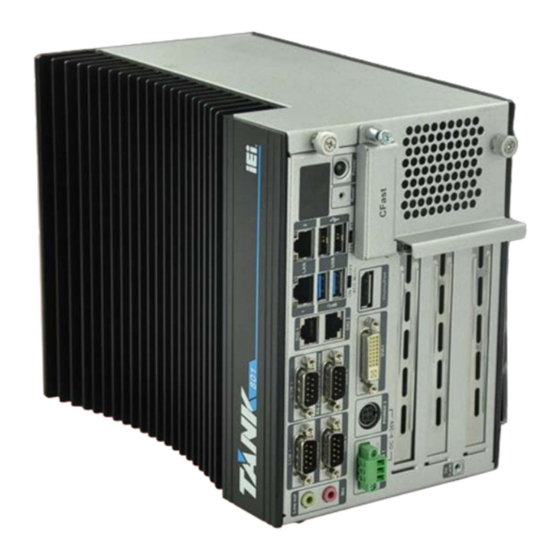
TANK-801 Em b e d d e d S ys te m 1.1 Ove rvie w Figure 1-1: TANK-801 The TANK-801 Series embedded system is a fanless system for wide range temperature environments. It is powered by the Intel® Celeron® J1900 2.0GHz quad core processor and has 2.0 GB of DDR3L memory. -
Page 15: Model Variations
TANK-801 Em b e d de d S ys te m 1.2 Mo d e l Va ria tio n s The model variations of the TANK-801 Series are listed below. Mo d e l No . CP U Exp a n s io n S lo ts Intel®... -
Page 16: Technical Specifications
TANK-801 Em b e d d e d S ys te m 1.4 Te c h n ic a l Sp e c ific a tio n s The TANK-801 technical specifications are listed in Table 1-2. S p e c ific a tio n s Fa n le s s Intel®... -
Page 17: Table 1-2: Technical Specifications
TANK-801 Em b e d de d S ys te m S p e c ific a tio n s Mini PCIe slot x 1 , In te rio r Exp e n s io n s SO-DIMM for IPMI Follow TANK-800 BP (1)2 x PCI + 1 x PCIe ( by1 signal ) Ba c kp la n e... -
Page 18: Connector Panel
TANK-801 Em b e d d e d S ys te m 1.5 Co n n e c to r P a n e l All external peripheral interface connectors are located on the rear panel of the TANK-801. The peripheral interface connectors are shown in Figure 1-2. Figure 1-2: TANK-801 Peripheral Connectors Connectors and buttons on the rear panel include the following. -
Page 19: Led Indicators
TANK-801 Em b e d de d S ys te m 2 x USB 2.0 ports 1 x Reset button 6 x LED indicators (Section 1.6) 1 x Power button 1 x CFast 1 x DisplayPort ... -
Page 20: Backplane Options
TANK-801 Em b e d d e d S ys te m 1.7 Ba c kp la n e Op tio n s The backplane options of the TANK-801 are shown below. Figure 1-4: 2P1E Figure 1-5: 1P2E Figure 1-6: 3P0E P a g e 8... -
Page 21: Table 1-3: Supported Signals
TANK-801 Em b e d de d S ys te m The supported signals of the backplane slots are listed below. Ba c kp la n e S lo t S ig n a l 2P 1E PCIe x16 PCIe x1 1P 2E PCIe x4 PCIe x1... -
Page 22: Dimensions
TANK-801 Em b e d d e d S ys te m NOTE: When using an expansion card with high power consumption, it is recommended to install an external power supply to the 12V power input connector on the backplane. The maximum dimensions of the expansion card should be 190 mm in length and 110 mm in width. -
Page 23: Unpacking
TANK-801 Em b e d de d S ys te m Ch a p te r Un p a c kin g P a g e 11... -
Page 24: Anti - Static Precautions
TANK-801 Em b e d d e d S ys te m 2.1 An ti-s ta tic P re c a u tio n s WARNING: Failure to take ESD precautions during installation may result in permanent damage to the TANK-801 and severe injury to the user. Electrostatic discharge (ESD) can cause serious damage to electronic components, including the TANK-801. -
Page 25: Unpacking Checklist
TANK-801 Em b e d de d S ys te m 2.3 Un pa c kin g Ch e c klis t NOTE: If some of the components listed in the checklist below are missing, please do not proceed with the installation. Contact the IEI reseller or vendor you purchased the TANK-801 from or contact an IEI sales representative directly. - Page 26 TANK-801 Em b e d d e d S ys te m Qu a n tity Ite m a n d P a rt Nu m b e r Im a g e S ta n d a rd HDD screw (P/N: 44043-030051-RS) Rubber foot pad screw (P/N: 44005-030061-RS)
-
Page 27: Installation
TANK-801 Em b e d de d S ys te m Ch a p te r In s ta lla tio n P a g e 15... -
Page 28: Installation Precautions
TANK-801 Em b e d d e d S ys te m 3.1 In s ta lla tio n P re c a u tio n s During installation, be aware of the precautions below: Read the user manual: The user manual provides a complete description of the TANK-801, installation instructions and configuration options. -
Page 29: Figure 3-1: Cfast Socket
TANK-801 Em b e d de d S ys te m Figure 3-1: CFast Socket S te p 2: Open the CFast socket cover (Figure 3-2). Figure 3-2: CFast Socket Cover S te p 3: Correctly align the CFast card with the socket and insert the CFast card into the socket. -
Page 30: Hard Disk Drive (Hdd) Installation
TANK-801 Em b e d d e d S ys te m Figure 3-3: CF Card Installation S te p 4: Reinstall the cover. 3.3 Ha rd Dis k Drive (HDD) In s ta lla tio n To install the hard drive, please follow the steps below: Remove the two retention screws on the rear panel and loosen the two S te p 1: thumbscrews on the front panel, slide the cover outward, and then lift the cover... -
Page 31: Figure 3-4: Unscrew The Cover
TANK-801 Em b e d de d S ys te m Figure 3-4: Unscrew the Cover S te p 2: Unplug the SATA signal and power cables connected to the TANK-801, and then put the cover on a flat surface (Figure 3-5). Figure 3-5: Remove the Cover from TANK-801 S te p 3: Attach the HDD to the HDD bracket, and then slide the HDD to connect the HDD... -
Page 32: Figure 3-6: Hdd Installation
TANK-801 Em b e d d e d S ys te m Figure 3-6: HDD Installation Secure the HDD with the HDD bracket by four retention screws (Figure 3-7). S te p 4: Figure 3-7: HDD Retention Screws Reconnect the SATA signal and power cables to the TANK-801. S te p 5: Reinstall the cover. -
Page 33: System Fan Installation
TANK-801 Em b e d de d S ys te m 3.4 S ys te m Fa n In s ta lla tio n To install the optional system fan, please follow the steps below: S te p 1: Remove the two retention screws on the rear panel and loosen the two thumbscrews on the front panel, slide the cover inwards, and then lift the cover up gently (Figure 3-4). -
Page 34: Mounting The System With Mounting Brackets
TANK-801 Em b e d d e d S ys te m S te p 1: Locate the DC-in terminal block connector. The location of the connector is shown in Figure 1-2. Align the pluggable DC-in terminal block with the DC-in terminal block connector S te p 2: on the TANK-801. -
Page 35: External Peripheral Interface Connectors
TANK-801 Em b e d de d S ys te m Left Side Panel Figure 3-10: Mounting Bracket Retention Screws Secure the brackets to the system by inserting two retention screws into each S te p 3: bracket (Figure 3-10). S te p 4: Drill holes in the intended installation surface. -
Page 36: Acc Mode Selection
TANK-801 Em b e d d e d S ys te m RS-232 RS-232/422/485 3.7.1 ACC Mo d e S e le c tio n The TANK-801 allows turning the ACC mode on or off. The setting can be made through the ACC mode switch on the external peripheral interface panel as shown below. -
Page 37: Audio Connector
TANK-801 Em b e d de d S ys te m Figure 3-12: AT/ATX Power Mode Switch 3.7.3 Au d io Co n n e c to r CN La b e l: Lin e o u t and Mic CN Typ e : Audio jack See Figure 1-2... -
Page 38: Digital Input/Output Connector
TANK-801 Em b e d d e d S ys te m The TANK-801 has one CFast socket. The location of the socket is shown in Figure 1-2. To install the CFast card, refer to Section 3.2. 3.7.5 Dig ita l In p u t/Ou tp u t Co n n e c to r CN La b e l: DIO1, DIO2 RJ-45... -
Page 39: Displayport Connector
TANK-801 Em b e d de d S ys te m Shell Table 3-1: DIO Connector Pinouts 3.7.6 Dis p la yP o rt Co n n e c to r The DisplayPort connector transmits a digital signal to compatible DisplayPort display devices such as a TV or computer screen. -
Page 40: Lan Connectors
TANK-801 Em b e d d e d S ys te m Locate the DVI connector. The location of the DVI connector is shown in S te p 1: Chapter 1. S te p 2: Align the DVI connector. Align the male DVI connector on the digital display device cable with the female DVI connector on the external peripheral interface. -
Page 41: Figure 3-18: Lan Connection
TANK-801 Em b e d de d S ys te m CN P in o u ts : See Table 3-2 The LAN connectors allow connection to an external network. S te p 1: Locate the RJ-45 connectors. The locations of the RJ-45 connectors are shown in Figure 1-2. -
Page 42: Power Input, 3-Pin Terminal Block
TANK-801 Em b e d d e d S ys te m Figure 3-19: RJ-45 Ethernet Connector The RJ-45 Ethernet connector has two status LEDs, one green and one yellow. The green LED indicates activity on the port and the yellow LED indicates the port is linked. See Table 3-3. -
Page 43: Power Input, 4-Pin Din Connector
TANK-801 Em b e d de d S ys te m 3.7.10 P owe r In p u t, 4-p in DIN Co n n e c to r CN La b e l: P OWER 2 4-pin DIN connector CN Typ e : CN Lo c a tio n : See Figure 1-2... -
Page 44: Figure 3-22: Serial Device Connector
TANK-801 Em b e d d e d S ys te m Figure 3-22: Serial Device Connector Secure the connector. Secure the serial device connector to the external S te p 3: interface by tightening the two retention screws on either side of the connector. Figure 3-23: DB-9 Connector Pinout Location Description (RS-232) Description (RS-422) -
Page 45: Serial Port Connectors
TANK-801 Em b e d de d S ys te m Table 3-5: RS-232/422/485 Connector Pinouts 3.7.12 RS -232 S e ria l P o rt Co n n e c to rs COM1, COM2 CN La b e l: DB-9 connectors CN Typ e : CN Lo c a tio n :... -
Page 46: Figure 3-24: Serial Device Connector
TANK-801 Em b e d d e d S ys te m Figure 3-24: Serial Device Connector Secure the connector. Secure the serial device connector to the external S te p 3: interface by tightening the two retention screws on either side of the connector. Figure 3-25: Serial Port Pinout Location Description Description... -
Page 47: Usb Connectors
TANK-801 Em b e d de d S ys te m 3.7.13 US B Co n n e c to rs CN La b e l: US B USB port CN Typ e : CN Lo c a tio n : See Figure 1-2 CN P in o u ts : See Table 3-7... -
Page 48: Internal Peripheral Interface Connectors
TANK-801 Em b e d d e d S ys te m Figure 3-26: USB Device Connection S te p 3: Insert the device connector. Once aligned, gently insert the USB device connector into the on-board connector. Description Description DATA- DATA- DATA+ DATA+... -
Page 49: Figure 3-27: Tpm Connector Location
TANK-801 Em b e d de d S ys te m Figure 3-27: TPM Connector Location S te p 3: Insert the TPM module. Make sure that pin 1 on the TPM module corresponds to pin 1 on the TPM connector (Figure 3-28). Figure 3-28: TPM Module Installation P a g e 37... -
Page 50: Powering O N /Off The System
TANK-801 Em b e d d e d S ys te m WARNING: Installing the TPM module will occupy one expansion slot. When the TPM module is installed, the user can install the expansion card, but need to remove the fixed bracket. TPM connector pinouts are shown in Table 3-8. -
Page 51: Power
TANK-801 Em b e d de d S ys te m Power off the system: press the power button for 5 seconds Figure 3-29: Power Button 3.10 P owe r There are two power connectors on the rear panel. Power 1 connector is a 3-pin terminal block that supports ACC On signal. -
Page 52: Acc On Mode
TANK-801 Em b e d d e d S ys te m Figure 3-30: Power Connectors LED In d ic a to r De s c rip tio n Standby mode. Power LED1 (Breathing Orange) Power-on mode. Power LED2 (Solid blue) Table 3-9: Power LED Indicators Description NOTE: The power LED turns off when the power cable is unplugged from the... -
Page 53: Acc Off Mode
TANK-801 Em b e d de d S ys te m 2. If ACC signal is low, the system will not boot up. If ACC ON signal is high (9 V~36 V), the system will boot up and work normally. 3. -
Page 54: Bios
TANK-801 Em b e d d e d S ys te m Ch a p te r BIOS P a g e 42... -
Page 55: Introduction
TANK-801 Em b e d de d S ys te m 4.1 In tro d u c tio n The BIOS is programmed onto the BIOS chip. The BIOS setup program allows changes to certain system settings. This chapter outlines the options that can be changed. 4.1.1 Sta rtin g S e tu p The UEFI BIOS is activated when the computer is turned on. -
Page 56: Getting Help
TANK-801 Em b e d d e d S ys te m Ke y Fu n c tio n Esc key Main Menu – Quit and not save changes into CMOS Status Page Setup Menu and Option Page Setup Menu -- Exit current page and return to Main Menu General help, only for Status Page Setup Menu and Option Page Setup Menu... -
Page 57: Main
TANK-801 Em b e d de d S ys te m The following sections completely describe the configuration options found in the menu items at the top of the BIOS screen and listed above. 4.2 Ma in The Main BIOS menu (BIOS Menu 1) appears when the BIOS Setup program is entered. The Main menu gives an overview of the basic system information. -
Page 58: Advanced
TANK-801 Em b e d d e d S ys te m CPU Information Memory Information GDP Information TXE Information The Main menu has two user configurable fields: S ys te m Da te [xx/xx/xx] Use the System Date option to set the system date. -
Page 59: Acpi Settings
TANK-801 Em b e d de d S ys te m Aptio Setup Utility – Copyright (C) 2013 American Megatrends, Inc. Main Advanced Chipset Boot Security Save & Exit > ACPI Settings System ACPI Parameters > Super IO Configuration > Hardware Monitor >... -
Page 60: Super Io Configuration
TANK-801 Em b e d d e d S ys te m ACP I S le e p Sta te [S 3 (S u s p e n d to RAM)] Use the ACPI Sleep State option to specify the sleep state the system enters when it is not being used. -
Page 61: Serial Port N Configuration
TANK-801 Em b e d de d S ys te m 4.3.2.1 S e ria l P o rt n Co n fig u ra tio n Use the Serial Port n Configuration menu (BIOS Menu 5) to configure the serial port n. Aptio Setup Utility –... - Page 62 TANK-801 Em b e d d e d S ys te m Serial Port I/O port address is 3F8h and the IO=3F8h; IRQ=3, 4,5,6,7,9,10,11,12 interrupt address is IRQ3,4,5,6,7,9,10,11,12 IO=2F8h; IRQ=3, Serial Port I/O port address is 2F8h and the interrupt address is IRQ3,4,5,6,7,9,10,11,12 4,5,6,7,9,10,11,12 ...
-
Page 63: Change Settings [Auto]
TANK-801 Em b e d de d S ys te m Serial Port I/O port address is 2E8h and the IO=2E8h; IRQ=3, 4,5,6,7,9,10,11,12 interrupt address is IRQ3,4,5,6,7,9,10,11,12 4.3.2.1.3 S e ria l P o rt 3 Co n fig u ra tio n ... -
Page 64: Device Mode [Rs232]
TANK-801 Em b e d d e d S ys te m De vic e Mo d e [RS 232] Use the Device Mode option to enable or disable the serial port. Enables serial port RS-232 support. RS232 EFAULT ... -
Page 65: Hardware Monitor
TANK-801 Em b e d de d S ys te m Serial Port I/O port address is 2F0h and the IO=2F0h; IRQ=3, 4,5,6,7,9,10,11,12 interrupt address is IRQ3,4,5,6,7,9,10,11,12 IO=2E0h; IRQ=3, Serial Port I/O port address is 2E0h and the interrupt address is IRQ3,4,5,6,7,9,10,11,12 4,5,6,7,9,10,11,12 ... -
Page 66: Smart Fan Mode Configuration
TANK-801 Em b e d d e d S ys te m P C He a lth Sta tu s The following system parameters and values are shown. The system parameters that are monitored are: System Temperatures: CPU Temperature System Temperature ... -
Page 67: Manual Pwm Setting
TANK-801 Em b e d de d S ys te m The fan adjusts its speed using these Auto PWM Mode settings: Temperature of Start Temperature of Off Start PWM Slope (Duty Cycle) Ma n u a l P WM S e ttin g Use the + or –... -
Page 68: Slope (Duty Cycle) [4 (Pwm)]
TANK-801 Em b e d d e d S ys te m Setting this value too high may cause the fan to rotate at full speed only when the CPU is at a very high temperature and therefore cause the system to be damaged. -
Page 69: Rtc Wake Settings
TANK-801 Em b e d de d S ys te m 4.3.4 RTC Wa ke S e ttin g s The RTC Wake Settings menu (BIOS Menu 8) configures RTC wake event. Aptio Setup Utility – Copyright (C) 2013 American Megatrends, Inc. Advanced Wake system with Fixed Time [Disabled]... -
Page 70: Serial Port Console Redirection
TANK-801 Em b e d d e d S ys te m If selected, the following appears with values that Enabled can be selected: *Wake up every day *Wake up date *Wake up hour *Wake up minute *Wake up second After setting the alarm, the computer turns itself on from a suspend state when the alarm goes off. -
Page 71: Terminal Type [Ansi]
TANK-801 Em b e d de d S ys te m Disabled the console redirection function Disabled EFAULT Enabled Enabled the console redirection function Te rm in a l Typ e [ANS I] Use the Terminal Type option to specify the remote terminal type.. ... -
Page 72: Stop Bits [1]
TANK-801 Em b e d d e d S ys te m No parity bit is sent with the data bits. None EFAULT Even The parity bit is 0 if the number of ones in the data bits is even. ... -
Page 73: Iei Feature
TANK-801 Em b e d de d S ys te m 4.3.6 iEi Fe a tu re Use the iEi Feature menu (BIOS Menu 10) to configure the iEi features. Aptio Setup Utility – Copyright (C) 2013 American Megatrends, Inc. Advanced iEi Feature Auto Recovery Function... -
Page 74: Socket 0 Cpu Information
TANK-801 Em b e d d e d S ys te m Aptio Setup Utility – Copyright (C) 2013 American Megatrends, Inc. Advanced CPU Configuration Socket specific CPU Information > Socket 0 CPU Information CPU Speed 2001 MHz ---------------------- 64-bit Supported : Select Screen ↑... -
Page 75: Ide Configuration
TANK-801 Em b e d de d S ys te m Aptio Setup Utility – Copyright (C) 2013 American Megatrends, Inc. Advanced Socket 0 CPU Information Intel(R) Celeron(R) CPU J1900 @ 1.99GHz CPU Signature 30678 ---------------------- Microcode Patch Max CPU Speed 1990 MHz : Select Screen Min CPU Speed... -
Page 76: Bios Menu 13: Ide Configuration
TANK-801 Em b e d d e d S ys te m Aptio Setup Utility – Copyright (C) 2013 American Megatrends, Inc. Advanced IDE Configuration Select IDE / ACHI SATA Mode [AHCI Mode] Serial-ATA Controller 1 [Enabled] --------------------- SATA Port1 Hotplug [Disabled] : Select Screen ↑... -
Page 77: Trusted Computing
TANK-801 Em b e d de d S ys te m 4.3.9 Tru s te d Co m p u tin g Use the Trusted Computing menu (BIOS Menu 14) to configure settings related to the Trusted Computing Group (TCG) Trusted Platform Module (TPM). Aptio Setup Utility –... -
Page 78: Usb Configuration
TANK-801 Em b e d d e d S ys te m 4.3.10 US B Co n fig u ra tio n Use the USB Configuration menu (BIOS Menu 15) to read USB configuration information and configure the USB settings. Aptio Setup Utility –... -
Page 79: Chipset
TANK-801 Em b e d de d S ys te m Legacy USB support disabled Disabled Auto Legacy USB support disabled if no USB devices are connected 4.4 Ch ips e t Use the Chipset menu (BIOS Menu 16) to access the Northbridge and Southbridge configuration menus. -
Page 80: North Bridge Configuration
TANK-801 Em b e d d e d S ys te m 4.4.1 No rth Brid g e Co n fig u ra tio n Use the North Bridge menu (BIOS Menu 17) to configure the North Bridge chipset. Aptio Setup Utility – Copyright (C) 2013 American Megatrends, Inc. Chipset Primary IGFX Boot Display [VBIOS Default]... - Page 81 TANK-801 Em b e d de d S ys te m Auto Default DVMT P re -Allo c a te d [256M] Use the DVMT Pre-Allocated option to set the amount of system memory allocated to the integrated graphics processor when the system boots.
-
Page 82: South Bridge Configuration
TANK-801 Em b e d d e d S ys te m The spread spectrum mode is enabled Enabled 4.4.2 S o u th Brid g e Co n fig u ra tio n Use the South Bridge Configuration menu (BIOS Menu 18) to configure the Southbridge chipset. -
Page 83: Usb 2.0 (Ehci) Support Enabled
TANK-801 Em b e d de d S ys te m USB function support enabled Enabled EFAULT US B 2.0 (EHCI) S u p p o rt [En a b le d ] Use the USB 2.0 (EHCI) Support BIOS option to enable or disable USB 2.0 support. ... -
Page 84: Azalia Hd Audio
TANK-801 Em b e d d e d S ys te m 4.4.2.1 Aza lia HD Au d io Use the Azalia HD Audio menu (BIOS Menu 19) to configure the Azalia HD audio settings. Aptio Setup Utility – Copyright (C) 2013 American Megatrends, Inc. Chipset Audio Configuration Control Detection of the... -
Page 85: Pci Express Configuration
TANK-801 Em b e d de d S ys te m 4.4.2.2 P CI Exp re s s Co n fig u ra tio n Use the PCI Express Configuration menu (BIOS Menu 20) to select the support type of the PCIe Mini slot. -
Page 86: Security
TANK-801 Em b e d d e d S ys te m 4.5 S e c u rity Use the Security menu (BIOS Menu 21) to set system and user passwords. Aptio Setup Utility – Copyright (C) 2013 American Megatrends, Inc. Security Password Description Set Administrator... -
Page 87: Boot
TANK-801 Em b e d de d S ys te m 4.6 Bo o t Use the Boot menu (BIOS Menu 22) to configure system boot options. Aptio Setup Utility – Copyright (C) 2013 American Megatrends, Inc. Boot Boot Configuration Select the keyboard Bootup NumLock State [On]... - Page 88 TANK-801 Em b e d d e d S ys te m Qu ie t Bo o t [En a b le d ] Use the Quiet Boot BIOS option to select the screen display when the system boots. ...
-
Page 89: Save & Exit
TANK-801 Em b e d de d S ys te m 4.7 S a ve & Exit Use the Save & Exit menu (BIOS Menu 23) to load default BIOS values, optimal failsafe values and to save configuration changes. Aptio Setup Utility – Copyright (C) 2013 American Megatrends, Inc. Save &... -
Page 90: Server Mgmt
TANK-801 Em b e d d e d S ys te m S a ve a s Us e r De fa u lts Use the Save as User Defaults option to save the changes done so far as user defaults. ... -
Page 91: System Event Log
TANK-801 Em b e d de d S ys te m 4.8.1.1 S ys te m Eve n t Lo g Use the System Event Log menu (BIOS Menu 19) to configure the event log. Aptio Setup Utility – Copyright (C) 2013 American Megatrends, Inc. Server Mgmt Enabling/Disabling Options Change this to anable or... -
Page 92: Bmc Network Configuration
TANK-801 Em b e d d e d S ys te m Wh e n S EL is Fu ll [Do No th in g ] Use When SEL is FULL option to select options for reactions to a full SEL. The following options are available: ... -
Page 93: A Regulatory Compliance
TANK-801 Em b e d de d S ys te m Ap p e n d ix Re g u la to ry Co m p lia n c e P a g e 81... - Page 94 TANK-801 Em b e d d e d S ys te m DECLARATION OF CONFORMITY This equipment is in conformity with the following EU directives: EMC Directive (2004/108/EC, 2014/30/EU) Low-Voltage Directive (2006/95/EC, 2014/35/EU) RoHS II Directive (2011/65/EU, 2015/863/EU) If the user modifies and/or install other devices in the equipment, the CE conformity declaration may no longer apply.
- Page 95 TANK-801 Em b e d de d S ys te m Deutsch [German] IEI Integration Corp, erklärt dieses Gerät entspricht den grundlegenden Anforderungen und den weiteren entsprechenden Vorgaben der Richtlinie 2014/53/EU. Eesti [Estonian] IEI Integration Corp deklareerib seadme seadme vastavust direktiivi 2014/53/EÜ...
- Page 96 TANK-801 Em b e d d e d S ys te m Lietuvių [Lithuanian] IEI Integration Corp deklaruoja, kad šis įranga atitinka esminius reikalavimus ir kitas 2014/53/EU Direktyvos nuostatas. Nederlands [Dutch] IEI Integration Corp dat het toestel toestel in overeenstemming is met de essentiële eisen en de andere relevante bepalingen van richtlijn 2014/53/EU.
- Page 97 TANK-801 Em b e d de d S ys te m Slovensko [Slovenian] IEI Integration Corp izjavlja, da je ta opreme v skladu z bistvenimi zahtevami in ostalimi relevantnimi določili direktive 2014/53/EU. Slovensky [Slovak] IEI Integration Corp týmto vyhlasuje, že zariadenia spĺňa základné požiadavky a všetky príslušné...
- Page 98 TANK-801 Em b e d d e d S ys te m Federal Communication Commission Interference Statement This equipment has been assembled with components that comply with the limits for a Class B digital device, pursuant to Part 15 of the FCC Rules. These limits are designed to provide reasonable protection against harmful interference in a residential installation.
-
Page 99: B Bios Options
TANK-801 Em b e d de d S ys te m Ap p e n d ix BIOS Op tio n s P a g e 87... - Page 100 TANK-801 Em b e d d e d S ys te m Below is a list of BIOS configuration options in the BIOS chapter. System Date [xx/xx/xx] ......................46 System Time [xx:xx:xx] .......................46 ACPI Sleep State [S3 (Suspend to RAM)] ................48 ...
- Page 101 TANK-801 Em b e d de d S ys te m Security Device Support [Disable] ..................65 USB Devices .........................66 Legacy USB Support [Enabled] ..................66 Primary IGFX Boot Display [VBIOS Default] ..............68 Primary Display [IGD] ......................68 ...
-
Page 102: C Safety Precautions
TANK-801 Em b e d d e d S ys te m Ap p e n d ix S a fe ty P re c a u tio n s P a g e 90... -
Page 103: Safety Precautions
TANK-801 Em b e d de d S ys te m C.1 S a fe ty P re c a u tio n s WARNING: The precautions outlined in this appendix should be strictly followed. Failure to follow these precautions may result in permanent damage to the TANK-801. -
Page 104: Product Disposal
TANK-801 Em b e d d e d S ys te m Electrostatic discharge (ESD) can cause serious damage to electronic components, including the TANK-801. Dry climates are especially susceptible to ESD. It is therefore critical that whenever the TANK-801 is opened and any of the electrical components are handled, the following anti-static precautions are strictly adhered to. -
Page 105: Maintenance And Cleaning Precautions
TANK-801 Em b e d de d S ys te m EU-wide legislation, as implemented in each Member State, requires that waste electrical and electronic products carrying the mark (left) must be disposed of separately from normal household waste. This includes monitors and electrical accessories, such as signal cables or power cords. - Page 106 TANK-801 Em b e d d e d S ys te m Water or rubbing alcohol – A cloth moistened with water or rubbing alcohol can be used to clean the TANK-801. Using solvents – The use of solvents is not recommended when cleaning the TANK-801 as they may damage the plastic parts.
-
Page 107: D Digital I/O Interface
TANK-801 Em b e d de d S ys te m Ap p e n d ix Dig ita l I/O In te rfa c e P a g e 95... -
Page 108: Introduction
TANK-801 Em b e d d e d S ys te m D.1 In tro d u c tio n The DIO connector on the TANK-801 is interfaced to GPIO ports on the Super I/O chipset. The DIO has both 4-bit digital inputs and 4-bit digital outputs. The digital inputs and digital outputs are generally control signals that control the on/off circuit of external devices or TTL devices. -
Page 109: Assembly Language Sample
TANK-801 Em b e d de d S ys te m D.2 As s e m b ly La n g u a g e S a m p le 1 AX, 6F08H ;setting the digital port as input AL low byte = value AH –... -
Page 110: E Hazardous Materials Disclosure
TANK-801 Em b e d d e d S ys te m Ap p e n d ix Ha za rd o u s Ma te ria ls Dis c lo s u re P a g e 98... - Page 111 TANK-801 Em b e d de d S ys te m The details provided in this appendix are to ensure that the product is compliant with the Peoples Republic of China (China) RoHS standards. The table below acknowledges the presences of small quantities of certain materials in the product, and is applicable to China RoHS only.
- Page 112 TANK-801 Em b e d d e d S ys te m 此附件旨在确保本产品符合中国 RoHS 标准。以下表格标示此产品中某有毒物质的含量符 合中国 RoHS 标准规定的限量要求。 本产品上会附有”环境友好使用期限”的标签,此期限是估算这些物质”不会有泄漏或突变”的 年限。本产品可能包含有较短的环境友好使用期限的可替换元件,像是电池或灯管,这些元 件将会单独标示出来。 部件名称 有毒有害物质或元素 铅 汞 镉 六价铬 多溴联苯 多溴二苯 醚 (P b ) (Hg ) (Cd ) (CR(VI)) (P BB) (P BDE) 壳体...
Need help?
Do you have a question about the TANK-801-BT and is the answer not in the manual?
Questions and answers