2-port and 4-port pna - microwave network analyzers (380 pages)
Summary of Contents for Keysight Technologies N5290/1A PNA Series
Page 1
Keysight Technologies 
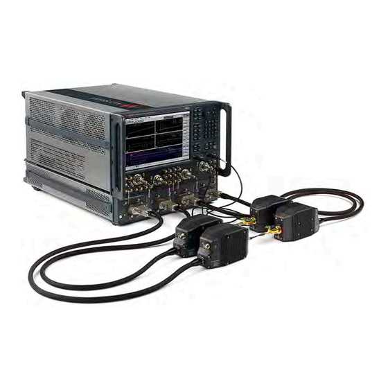
N5290/1A PNA Series 2-Port and 4-Port Microwave Network Analyzer System (900 Hz - 110 GHz / 900 Hz - 120 GHz) Use this manual in conjunction with the following documents: -PNA Series Network Analyzer Embedded Help System (Online at: http://na.support.keysight.com/pna)
Keysight Technologies N5290/1A PNA and PNA-X Series 2-Port and 4-Port Microwave Network Analyzer Systems Service Guide Safety and Regulatory Information Information in This Chapter This chapter provides safety information that will help protect you and your system’s equipment. It also contains information that is required by various government regulatory agencies.
Safety and Regulatory Information Safety Symbols Safety Symbols The following safety symbols are used throughout this manual. Familiarize yourself with each of the symbols and its meaning before operating this instrument. Caution denotes a hazard. It calls attention to a procedure that, if not correctly performed or adhered to, could result in damage to or destruction of the instrument.
Safety and Regulatory Information General Safety Considerations General Safety Considerations Safety Earth Ground This is a Safety Class I product (provided with a protective earthing ground incorporated in the power cord). The mains plug shall only be inserted in a socket outlet provided with a protective earth contact.
Page 14
Safety and Regulatory Information General Safety Considerations Supply voltages which oscillate between the two normal input ranges of the autoranging line voltage input will damage the power supply. In rare cases, this damage has become a user safety concern. If unstable power levels are expected, the analyzer input power must be buffered by a line conditioner.
Safety and Regulatory Information General Safety Considerations Servicing These servicing instructions are for use by qualified personnel only. To avoid electrical shock, do not perform any servicing unless you are qualified to do so. Danger of explosion if battery is incorrectly replaced. Replace only with the same or equivalent type recommended.
Page 16
Safety and Regulatory Information General Safety Considerations There are no replaceable fuses in the mains input or within the power supply assembly. Keysight personnel: after calibration is completed, attach four “calibration void if seal broken” stickers to the PNA as shown in Figure 1-1.
Safety and Regulatory Information Electrostatic Discharge Protection Electrostatic Discharge Protection This is important. If not properly protected against, electrostatic discharge can seriously damage your analyzer, resulting in costly repair. Protection against electrostatic discharge (ESD) is essential while removing assemblies from or connecting cables to the network analyzer. Static electricity can build up on your body and can easily damage sensitive internal circuit elements when discharged.
Safety and Regulatory Information Electrostatic Discharge Protection Figure 1-2 ESD Protection Setup ESD Equipment Required for the Installation Description Keysight Part Number ESD grounding wrist strap 9300-1367 5-ft grounding cord for wrist strap 9300-0980 2 x 4 ft conductive table mat and 15-ft grounding wire 9300-0797 ESD heel strap (for use with conductive floors) 9300-1308...
Safety and Regulatory Information Regulatory Information Regulatory Information This section contains information that is required by various government regulatory agencies. Instrument Markings Familiarize yourself with these instrument markings and their meanings before operating the instrument. Some instrument markings may not appear on your analyzer. The instruction documentation symbol.
If the battery on your network analyzer’s CPU board needs to be disposed of, dispose of it in accordance with your country’s requirements. If required, you may return the battery to Keysight Technologies for disposal. Refer to “Contacting Keysight” on page 2-7 for assistance.
Page 21
Safety and Regulatory Information Regulatory Information South Korean Class A EMC declaration: This equipment has been conformity assessed for use in business environments. In a residential environment this equipment may cause radio interference. — This EMC statement applies to the equipment only for use in business environment.
Safety and Regulatory Information N5292A Test Set Equipment Ratings N5292A Test Set Equipment Ratings Table 1-1 N5292A Equipment Ratings Nominal voltage and or range 100/120 or 220/240 VAC Nominal frequency and or range 50/60 Hz Power in watts, VA or current 210 W MAX 1-12 Keysight N5290/1A Service Guide...
Safety and Regulatory Information Environmental Requirements Environmental Requirements Ventilation Requirements: When installing the product in a cabinet, the convection into and out of the product must not be restricted. The ambient temperature (outside the cabinet) must be less than the maximum operating temperature of the instrument by 4 °C for every 100 watts dissipated in the cabinet.
Safety and Regulatory Information Environmental Requirements System Heating and Cooling Install air conditioning and heating, if necessary, to maintain the ambient temperature within the appropriate range (as given in the table above). Air conditioning capacity must be consistent with the BTU ratings given in Table 1-1 on page 12 Table 1-2 on page...
Safety and Regulatory Information Space Requirements Space Requirements Standard installation of the N5290/1A system includes configuration and installation of the system on a customer provided lab bench or table top of adequate size and strength. N5290/1A System Weight and Dimensions Table 1-4 N5290/1A System Weight and Dimensions Model...
Page 26
Safety and Regulatory Information Space Requirements Table 1-5 N5290/1A System Components Weights and Dimensions Model Weight Height Width Depth N5222B, 2-Port PNA, Option 205 27 kg 27.91 cm 48.29 cm 57.8 cm (60 lb) nominal (11.0 in) (19.0 in) (22.7 in) N5227B, 2-Port PNA, Option 205 42.2 kg 27.91 cm...
Safety and Regulatory Information Site Preparation Site Preparation Install the instrument so that the detachable power cord is readily identifiable and is easily reached by the operator. An externally installed switch or circuit breaker (which is readily identifiable and is easily reached by the operator) should be used as the disconnecting device.The detachable power cord can also be used to disconnect the mains circuits from the mains supply before other parts of the instrument.
Page 28
Safety and Regulatory Information Site Preparation 1-18 Keysight N5290/1A Service Guide...
Keysight Technologies N5290/1A PNA and PNA-X Series 2-Port and 4-Port Microwave Network Analyzer Systems Service Guide General Product Information STOP! If you have a problem with your N5293A or N5295A millimeter-wave head, you must return it to the factory for repair. Refer to “Contacting...
Page 30
General Product Information Information in This Chapter Section Title Summary of Content Start Page Keysight Support, Services, and The Internet address (URL) for on-line assistance. page 2-6 Assistance Service and support options available. Calibration options available. Important information about shipping your analyzer to Keysight for service or repair.
General Product Information N5290/1A System Options, Accessories, and Upgrades Available N5290/1A System Options, Accessories, and Upgrades Available To see a list of the accessories and upgrades available for the N5290/1A Systems, including ordering information, refer to the Keysight Millimeter Wave Network Analyzers (N5290A/N5291A) Configuration Guide, available online at https://literature.cdn.keysight.com/litweb/pdf/5992-2179EN.pdf.
Page 32
General Product Information Required Service Test Equipment Critical Specifications Recommended Alternate Model Equipment Model or Part or Part Number Number Calibration and Verification Tools 1.0 Precision Calibration Kit 85059B P,A,T,V ECal module Recommended, but not N4691D Equivalent or (300 kHz to 26.5 GHz) required.
Page 33
General Product Information Required Service Test Equipment Critical Specifications Recommended Alternate Equipment Model or Part Model Number Number Tools 1/4-inch and 5/16-inch Thin profile 8710-0510 open-end wrench 1/4-inch (14 mm), open-end 0.5 N-m torque wrench (4 lb-in) settings (for semi-rigid cables) 5/16-inch (8 mm) open-end 1.3 N-m...
— R1282A Return to Keysight Calibration Plan The analyzer is delivered with a one-year calibration certificate. Options are available to have Keysight Technologies provide three or five year calibration coverage (perform the annual calibration two or four times). Options for basic calibration or SO/IEC 17025 or ANSI/NCSL Z540.3–2006 standards compliant calibrations are available.
Keysight for repair If you wish to send your system to Keysight Technologies for service or repair: — Contact Keysight to open a service order. Refer to “Contacting Keysight”...
General Product Information Keysight Support, Services, and Assistance Product Selection and Configuration Assistance, Education and Training http://www.keysight.com/main/contactInformation Keysight N5290/1A Service Guide...
Keysight Technologies N5290/1A PNA and PNA-X Series 2-Port and 4-Port Microwave Network Analyzer Systems Service Guide System Tests and Adjustments IMPORTANT! Before you begin any testing on a System or instrument, always inspect the connectors on the instrument, the calibration kit, cables and adapters.
System Tests and Adjustments Information in This Chapter Chapter Three at-a-Glance Section Title Summary of Content Before You Begin Items to consider or procedures to perform before testing is begun: — Verify the Operating Environment — Protect Against Electrostatic Discharge (ESD) —...
System Tests and Adjustments Before You Begin Before You Begin IMPORTANT! Before you begin any testing on a System or instrument, always inspect the connectors on the instrument, the calibration kit, cables and adapters. Complete the Installation procedures in Chapter 3, "System Installation" of the N5292-90002 N5290/1/A Microwave Network Analyzer System Installation Guide to assemble and configure the system.
System Tests and Adjustments Before You Begin Torquing Connections All connections made during the System Check and System Performance Verification procedures should be carefully torqued using the tools provided in the 85059B kit. IMPORTANT! For N5224/5B, N5244/5B, and N5267B PNAs When connecting the 5292-20014 semirigid cable it is critical that the 2.4 mm end is connected to the PNA’s REFn SOURCE OUT port and the SMA end is connected to the N5292A test set’s LO Band connector.
Prior to making connections to your analyzer, carefully review the information about inspecting, cleaning, and gaging connectors. Refer to the calibration kit documentation for detailed connector care information. For course numbers about additional connector care instruction, contact Keysight Technologies. Refer to “Contacting Keysight” on page 2-7. Table 3-1...
Page 42
System Tests and Adjustments Before You Begin Table 3-1 Connector Care Quick Reference Guide — Get liquid into plastic support beads — Use isopropyl alcohol — Clean connector threads Gaging Connectors — Clean and zero the gage before use Do Not —...
System Tests and Adjustments ANSI/NCSL Z540.3–2006 and ISO/IEC 17025 Verification ANSI/NCSL Z540.3–2006 and ISO/IEC 17025 Verification To learn about the criteria for ANSI/NCSL Z540.3–2006 and ISO/IEC 17025 verification, refer to the service guide for your analyzer. Refer to https://www.keysight.com/find/pna or for your system, refer to http://na.support.keysight.com/mmwave/.
System Tests and Adjustments The N5290/1A Millimeter Test System Preliminary Check N5290/1A Incoming Electrical Inspection In this section the manual receiver display test is ran to check the general system integrity. IMPORTANT! For N5224/5B, N5244/5B, and N5267B PNAs When connecting the 5292-20014 semirigid cable it is critical that the 2.4 mm end is connected to the PNA’s REFn SOURCE OUT port and the SMA end is connected to the N5292A test set’s LO Band connector.
Page 45
System Tests and Adjustments The N5290/1A Millimeter Test System Preliminary Check — “If the Head Check Fails” on page 3-15 Initializing the N5290/1A Broadband System If the N5290/1A system is already installed and no changes have occurred to any of the instruments or cables, refer to “The Head Cable Checks”...
Page 46
System Tests and Adjustments The N5290/1A Millimeter Test System Preliminary Check 2. The Millimeter Configuration window that opens should have N5290A Broadband or N5291A Broadband highlighted. Else, press N5290A Broadband or N5291A Broadband. Refer to Figure 3-3 on page 3-10. 3.
Page 47
System Tests and Adjustments The N5290/1A Millimeter Test System Preliminary Check 4. When finished, the following dialog box is displayed. Remove the load and press Finish. Refer to Figure 3-5 on page 3-11. Figure 3-5 Millimeter Installation Cal – Dialog Box Load Calibration "Finish" 5.
Page 48
System Tests and Adjustments The N5290/1A Millimeter Test System Preliminary Check For more, refer to “Required Service Test Equipment” on page 2-3. Equipment Type Model of Part Number Alternate Model or Part Number Calibration kit, 1.0 mm 85059B Equivalent or better 1.00 mm (f) to 1.00 mm (f) (short thru) 11920-60002 a.
Page 49
System Tests and Adjustments The N5290/1A Millimeter Test System Preliminary Check g. If your instruments are not warmed up for two hours, repeat step f. Else, skip to next step. 5. Both traces should track each other and look relatively flat. Refer to Figure 3-7 on page 3-13.
Page 50
System Tests and Adjustments The N5290/1A Millimeter Test System Preliminary Check Figure 3-8 Lifting the cable at the bend and watching for trace spikes/instability 7. Gently extend the head (exercising care to not overextend) and rotate side to side (less than 90 degree) making sure traces are relatively stable and still tracking each other.
Page 51
System Tests and Adjustments The N5290/1A Millimeter Test System Preliminary Check If the Head Check Fails 1. Clean the test ports, shorts and adapters. Torque to specification. Repeat the check. 2. If the head check still fails and the failure is one port only: Then swap the suspect head onto one of the other good ports (i.e., requires running the N5290/1A system adjustments.
System Tests and Adjustments N5292A Functional Verification Procedure N5292A Functional Verification Procedure STOP! This section assumes you have completed the N5290/1A Incoming Electrical Inspection and have isolated the problem to the N5292A test set. If you are not sure the system problem is in the N5292A and you have not completed the N5290/1A Incoming Electrical Inspection, refer to “The N5290/1A Millimeter Test System Preliminary Check”...
Page 53
System Tests and Adjustments N5292A Functional Verification Procedure — LO power verification for LOPA/LODA/Phase compensation/Test set mother board (TSMB) PCA assemblies — Test set cabling paths front panel connectors to Test set mother board (TSMB) This section contains the following: —...
Page 54
System Tests and Adjustments N5292A Functional Verification Procedure b. Use x5 as connector savers on the rear panel IF ports (optional). Use x3 for front panel wideband IF and LFE Eterms. c. N5240-60092 is the longer cable that is used on the PNA LO OUT to N5292A test set’s LO IN (rear panel) Required Equipment —...
Page 55
System Tests and Adjustments N5292A Functional Verification Procedure Figure 3-10 Power Supply fixture (ET57265, N5292-60130), mm Head Heater DAC, and TSMB verification Keysight N5290/1A Service Guide 3-19...
Page 56
System Tests and Adjustments N5292A Functional Verification Procedure — RF Fixture, Test Set Port Cabling and TSMB Verification – N5292-60128. Figure 3-11 on page 3-20. Figure 3-11 S-Parameters fixture (N5292-60129), test set IF/RF port paths (from test set to test set mother board (TSMB)) verification 3-20 Keysight N5290/1A Service Guide...
Page 57
System Tests and Adjustments N5292A Functional Verification Procedure — LO Calibration and Verification – N5292-60127. See Figure 3-12 on page 3-21. Figure 3-12 LO fixture – (N5292-60127), LO calibration/verification and TSMB verification — S-Parameters fixture – RF verification. See Figure 3-13 on page 3-21.
Page 58
System Tests and Adjustments N5292A Functional Verification Procedure — Three SMA or 3.5 mm adapters (female to female) — Voltmeter — Power sensor and compatible power meter. The power sensor must be capable of measuring from -10 dBm to +15 dBm at a frequency of 8 GHz. A E4413A power sensor may be used.
System Tests and Adjustments N5292A Functional Verification Procedure Equipment required: — 26.5 GHz PNA-8 with Option 020 — Optional: USB stick (to download the N5292A Test Set Functional Verification Test software ( ) from Keysight.com to load into your PNA. Refer to http://na.support.keysight.com/pna/files/N5292A_TESTS.exe and to “PNA Calibration (Pna Cal) and Loading the N5292A Test Set Functional...
Page 60
System Tests and Adjustments N5292A Functional Verification Procedure — “LO Power Calibration, Adjustment, and Verification” on page 3-24 — “Millimeter-wave (mmW) Heads Sense Voltage (Head Detect)” on page 3-28 — “Millimeter-wave (mmW) Heads Sense Voltage (Head Detect)” on page 3-28 —...
Page 61
System Tests and Adjustments N5292A Functional Verification Procedure Procedure: 1. On the PNA: Press Service > Service Menu > Adjustments > EE Adjust > LO Drive OR Run N5292A Launch Test software and click Insertion Loss/Match. 2. On the N5292A: Connect LO Fixture (N5292-60127) to port 1. 3.
Page 62
System Tests and Adjustments N5292A Functional Verification Procedure Figure 3-16 Typical LO maximum power (with path corrections) Millimeter (mm) Head Heater DAC and Power Supplies Check (Heater Dac/Voltage) IMPORTANT! Ensure that: N5292A test set is powered down, before connecting the power supply —...
Page 63
System Tests and Adjustments N5292A Functional Verification Procedure — Power Supply fixture (N5292-60130) — PC with Launch Test application loaded ( Procedure: Refer to Figure 3-14 on page 3-23 and to Figure 3-17 on page 3-27. 1. Press Header Dac/Voltage. 2.
Page 64
System Tests and Adjustments N5292A Functional Verification Procedure Millimeter-wave (mmW) Heads Sense Voltage (Head Detect) This section assumes you have already downloaded the Launch Test application to your PC. If not, refer to “PNA Calibration (Pna Cal) and Loading the N5292A Test Set Functional Verification Software (Launch Test)”...
Page 65
System Tests and Adjustments N5292A Functional Verification Procedure After port has been detected, the screen will display "Head Detected". 7. When done, remove the jack screw tool from the port. 8. Repeat steps through for the other ports. Else, press Exit. Keysight N5290/1A Service Guide 3-29...
Page 66
System Tests and Adjustments N5292A Functional Verification Procedure Figure 3-18 Screwdriver Adjusting Front Panel Connector Screw to Adjust TSMB LEDs to Green Use test screw (SV 081-80-009) and screwdriver (cw) to adjust front panel screw ~2 to 5 turns from the zero-point (no threads screwed in).
Page 67
System Tests and Adjustments N5292A Functional Verification Procedure Figure 3-19 Screwdriver and TSMB with LEDs S-Parameters (Insertion Loss/Match) This section assumes you have already downloaded the Launch Test application to your PC. If not, refer to “PNA Calibration (Pna Cal) and Loading the N5292A Test Set Functional Verification Software (Launch Test)”...
Page 68
System Tests and Adjustments N5292A Functional Verification Procedure Figure 3-20 ECal Connected to Ports 1 and 2 for 2-port Calibration and Insertion Loss/Transmission baseline integrity Measurements 3. Verify Test Set S-Parameters (Using the Launch Test application): Fixtures that are used are shown in Figure 3-21 on page 3-34 along with a typical ET setup.
Page 69
System Tests and Adjustments N5292A Functional Verification Procedure When a defective cable or connector has been replaced and the test set has been repaired, the following tests are required: Test set and N5290A/91 A system calibration — — Insertion Loss/Match-S-parameters (verify PNA Cal has been completed).
Page 70
System Tests and Adjustments N5292A Functional Verification Procedure Figure 3-21 ECal Connected to Ports 1 and 2 for 2-port Calibration and Insertion Loss/Transmission Measurements 3-34 Keysight N5290/1A Service Guide...
Page 71
System Tests and Adjustments N5292A Functional Verification Procedure Figure 3-22 90–degree Adapters Connected Figure 3-23 Low-Band ET (ET57259–2) Connected Keysight N5290/1A Service Guide 3-35...
Page 72
System Tests and Adjustments N5292A Functional Verification Procedure Figure 3-24 Low Band (LFE) Eterm Test Connections: PNA port 1 (left) connected to ET Ref IF. PNA port 2 (right) Connects to Test Set Ref IF out. 3-36 Keysight N5290/1A Service Guide...
Page 73
System Tests and Adjustments N5292A Functional Verification Procedure Figure 3-25 Low Band (LFE) Eterm Test Connections: PNA port 1 connects to the ET LO (Low) Band. PNA port 2 (bottom) connects to the Test Set NA Port. Figure 3-26 Low Band (LFE) Eterm Test Connections: Verifies ~60 ohms with DVM from ground to center conductor.
Page 74
System Tests and Adjustments N5292A Functional Verification Procedure Figure 3-27 Test IF Path Figure 3-28 REF IF Path 3-38 Keysight N5290/1A Service Guide...
Page 75
System Tests and Adjustments N5292A Functional Verification Procedure Figure 3-29 RF Path Figure 3-30 Low Band Extension (LFE) Path Keysight N5290/1A Service Guide 3-39...
Page 76
System Tests and Adjustments N5292A Functional Verification Procedure Test Set Connector and Cable Verification When a defective cable or connector has been replaced and the test set has been repaired, the following tests are required: Test set and N5290A/91 A system calibration —...
System Tests and Adjustments N5290/1A Millimeter-wave Test System Operator’s Check N5290/1A Millimeter-wave Test System Operator’s Check STOP! This section assumes you have completed the N5292A test set Operator's Check. If you have not completed the N5292A test set Operator's Check, refer to “N5292A Functional Verification Procedure”...
Page 78
System Tests and Adjustments N5290/1A Millimeter-wave Test System Operator’s Check Performing the Operator’s Check 1. Press UTILITY > System > Service > Verification > Operator's Check. 2. In the PNA Operator's Check dialog box (refer to Figure 3-32 on page 3-43), under Configure, select either: —...
Page 79
System Tests and Adjustments N5290/1A Millimeter-wave Test System Operator’s Check Figure 3-32 Operator’s Check Dialog Boxes Keysight N5290/1A Service Guide 3-43...
System Tests and Adjustments If the N5290/1A Operator’s Check Fails If the N5290/1A Operator’s Check Fails 1. Clean the test ports, shorts, and adapters. Torque to specification. Repeat the check. 2. Run the adjustment tests and repeat the Operator’s Check. Refer “Adjustments”.
System Tests and Adjustments Test Management Environment (TME) Performance Tests (N5290/1 A Millimeter System Only) Test Management Environment (TME) Performance Tests (N5290/1 A Millimeter System Only) The performance tests verify the electrical performance of your N5290/1 A Millimeter System. For more information, refer to the TME webpage at http://cal.software.keysight.com (N7840A) and to http://cal.software.keysight.com/PNA/Help/N7840AWebHelp.htm.
Page 82
System Tests and Adjustments Test Management Environment (TME) Performance Tests (N5290/1 A Millimeter System Only) characterized by NPL or NIST (or another NMI). Please order Option H99 to get electronic data for easy import into the N7800A (avoids manual entry). The overall resulting N7800A measurement uncertainties then reflects these lower device uncertainties.
System Tests and Adjustments Adjustments Adjustments These adjustments are firmware-driven tests that are used to adjust your N5290/1A mmW System or N5292A after PCA, cable, or connector has been replaced. If multiple adjustments are to be performed, perform them in the order listed. N5290/1A System Only Run these tests after the PNA, heads, or N5292A test set have been repaired and the system is ready for final testing.
Page 84
System Tests and Adjustments Adjustments Accessories Used in the Adjustments For more, refer to “Required Service Test Equipment” on page 2-3. Equipment Type Part Number Calibration and Verification Tools 1.0 mm calibration kit 85059B ECal module (Recommended, but not required) N4691B 300 kHz to 26.5 GHz Power supply load ET...
System Tests and Adjustments Adjustments Figure 3-33 Select Desired Adjustment Menu LO Adjustment for mm Mode This adjustment is used for the N5292A and for the N5290/1 A system. Refer to “LO Power Calibration, Adjustment, and Verification” on page 3-24. IF Gain Adj for mm Mode Run test and follow the prompts.
Page 86
System Tests and Adjustments Adjustments 3-50 Keysight N5290/1A Service Guide...
Keysight Technologies N5290/1A PNA and PNA-X Series 2-Port and 4-Port Microwave Network Analyzer Systems Service Guide N5290/91A Troubleshooting IMPORTANT! Before you begin any testing on a System or instrument, always inspect the connectors on the instrument, the calibration kit, cables and adapters.
N5290/91A Troubleshooting Information in This Chapter Chapter Four at-a-Glance Section Title Summary of Content Start Page Getting Started with A starting point for troubleshooting. page 4-3 Troubleshooting Power Supplies and Fans Power-up problems: page 4-6 — Power supply problems No DC Power for page 4-8 —...
N5290/91A Troubleshooting Getting Started with Troubleshooting Getting Started with Troubleshooting STOP! If you have a problem with your N5293A or N5295A millimeter-wave head, you must return it to the factory for repair. Refer to “Contacting Keysight” on page 2-7. For network analyzer troubleshooting, see the "Troubleshooting" chapter in the service guide for your PNA.
Page 90
N5290/91A Troubleshooting Getting Started with Troubleshooting Figure 4-1 Troubleshooting Organization Flowchart “N5290/1A Go to Millimeter-Wave System Troubleshooting” on page 4-5. “N5292A Test Controller Troubleshooting” Go to on page 4-6 “No DC Power for and to Millimeter-wave Modules” on page 4-8. “No DC Power for Go to Millimeter-wave...
N5290/91A Troubleshooting N5290/1A Millimeter-Wave System Troubleshooting N5290/1A Millimeter-Wave System Troubleshooting STOP! This chapter assumes you have performed the N5290/1A system checks in Chapter 3, “System Tests and Adjustments,” and have isolated the N5292A test set as the problem instrument. If you have not isolated the N5292A test set as the problem, then go back and perform the checks Chapter STOP! If you have a problem with your N5293A or N5295A millimeter-wave...
N5290/91A Troubleshooting N5292A Test Controller Troubleshooting N5292A Test Controller Troubleshooting STOP! This chapter assumes you have performed the N5290/1A system checks in Chapter 3, “System Tests and Adjustments,” and have isolated the N5292A test set as the problem instrument. If you have not isolated the N5292A test set as the problem, then go back and perform the checks Chapter N5292A test set controller troubleshooting can only be done by...
Page 93
N5290/91A Troubleshooting N5292A Test Controller Troubleshooting d. Ensure the TSMB DC Supply indicator LEDs are on. If not, suspect power supply (0950-0516) or front panel Standby switch. Using a DVM measure the power supply terminal connections. Refer to the label on the power supply for voltages on the terminals screws. Refer to “Verifying the A1 power supply”...
N5290/91A Troubleshooting N5292A Test Controller Troubleshooting No DC Power for Millimeter-wave Modules This section isolates a faulty millimeter-wave module or a faulty N5292A test set. This section contains the following procedures: — “Procedure for identifying a faulty millimeter head:” — “Verifying the A5 Test Set Motherboard (TSMB)”...
Page 95
N5290/91A Troubleshooting N5292A Test Controller Troubleshooting 4. On the test set head, check to see if the head LEDs are working correctly (LEDs illuminated red). If yes, run mm Mode Operations Check. Refer to Chapter 3 and to “The N5290/1A Millimeter Test System Preliminary Check”...
Page 96
N5290/91A Troubleshooting N5292A Test Controller Troubleshooting Figure 4-2 TSMB LEDs and the status of the FPGAs. When the magenta LED(s) is illuminated the FPGA(s) are not enabled (i.e., verify +4.4V, +6.4V, and 9.2V). TSMB FPGA fault detection LEDs illuminating magenta (i.e., when the magenta LED is illuminated the FPGA has not been enabled—need to verify: +4.4V, +6.4V, and +9.2V.) 4-10...
Page 97
N5290/91A Troubleshooting N5292A Test Controller Troubleshooting Table 4-1 Test Set Motherboard (TSMB) DC Test Point Values Voltage (+/–0.2V) Fuse # Test Point (TP) Test Point (Other) Group 1 TP13 –– 15 VF TP14 –– –15VF TP16 –– 5.2 VF TP17 ––...
Page 98
N5290/91A Troubleshooting N5292A Test Controller Troubleshooting Figure 4-3 Overview of TSMB and Test Point Locations 4-12 Keysight N5290/1A Service Guide...
Page 99
N5290/91A Troubleshooting N5292A Test Controller Troubleshooting Figure 4-4 Group 1 Test Point Details, including F1–F8 Keysight N5290/1A Service Guide 4-13...
Page 100
N5290/91A Troubleshooting N5292A Test Controller Troubleshooting Figure 4-5 Test Set Head DC Volts (e.g., is for port 3 (i.e., Other ports Port 1 (A), Port 2 (B), and Port 4 (D), are similar). 4-14 Keysight N5290/1A Service Guide...
Page 101
N5290/91A Troubleshooting N5292A Test Controller Troubleshooting Figure 4-6 Group 2 Test Point Details Keysight N5290/1A Service Guide 4-15...
Page 102
N5290/91A Troubleshooting N5292A Test Controller Troubleshooting Figure 4-7 Group 3 Test Point Details Verifying A5 Test Set Motherboard Connectors, Cables, and Voltages 1. Power down the test set and remove the top and bottom covers. Refer to Chapter 7 “Removing the Outer Cover” on page 7-8.
N5290/91A Troubleshooting N5292A Test Controller Troubleshooting 5. If the J3-J6 voltages are OK, and only one port is failing, and the head(s) are working OK on other ports, then swap out a known good J3–J6 cable and retest that port. Refer to Figure 4-8 on page 4-18 and to step 7.
Page 104
N5290/91A Troubleshooting N5292A Test Controller Troubleshooting Figure 4-8 Using the Power Supply Fixture to Check the Test Set Motherboard (TSMB) J3 (Port 1)–J6 (Port 4) Connector’s DC Test Point Values – Verifies the mm Heads Have the Correct Voltages (i.e., J3 (Port 1) is shown, the other ports are similar) 4-18 Keysight N5290/1A Service Guide...
Page 105
N5290/91A Troubleshooting N5292A Test Controller Troubleshooting 4. Power down the test set and remove the cover. Refer to Chapter 7 “Removing the Cover” on page 7-8. 5. On the test set motherboard (TSMB), verify the continuity of the F1–F8 fuses. If necessary, use the "Spare" fuse (F9). Refer to Table 4-1 on page 4-11 Figure...
Page 106
N5290/91A Troubleshooting N5292A Test Controller Troubleshooting 6. Verify the test set is powered down: On the A1 power supply, verify the wires are correctly seated. Refer to Figure 6-18 on page 6-35. If the wires were not connected correctly, reconnect, power up the TSMB, and recheck the power supply test fixture voltages shown in Figure 4-8 on page...
Page 107
N5290/91A Troubleshooting N5292A Test Controller Troubleshooting Figure 4-10 Test Set Head DC Volts (e.g., is for port 3 (i.e., Other ports Port 1 (A), Port 2 (B), and Port 4 (D), are similar). Keysight N5290/1A Service Guide 4-21...
N5290/91A Troubleshooting N5292A Test Controller Troubleshooting Figure 4-11 Example of J7-J11 Digital Pin-Outs Figure 4-12 Test Set Motherboard DC Test Point Values Verifying the A2 LOPA, A3 LODA, and A4 Phase Compensation Boards Refer to Figure 4-13 on page 4-23, for the following sections: —...
Page 109
N5290/91A Troubleshooting N5292A Test Controller Troubleshooting Figure 4-13 Location of the A2 LOPA, A3 LODA, and A4 Phase Compensation Boards Verifying the A2 LOPA (LO Preamplifier) This procedure verifies the LO preamplifier PC’s port 1 through port 4 behavior. 1. Power down the test set and remove the outer cover. Refer to Chapter 7 “Removing the Cover”...
Page 110
N5290/91A Troubleshooting N5292A Test Controller Troubleshooting 5. If one or more LEDs is faulty, verify the power out one of the LOPA ports. The power should measure ~0 dB out of either port. If the power is not correct, replace the LOPA board. If the power is correct, but the LED is faulty, replace the LOPA board.
N5290/91A Troubleshooting N5292A Test Controller Troubleshooting Figure 4-14 Verifying the A3 LODA LEDs Verifying the A4 Phase Compensation Board 1. Verify J54 cable connector is seated correctly, else power down and reconnect. 2. Disconnect the suspect semi-rigid cable from suspect port (J5, J6, J7. or J8).
Page 112
N5290/91A Troubleshooting N5292A Test Controller Troubleshooting Equipment required: — Freeze spray — PNA 10 MHz to 26.5 GHz (minimum) — Millimeter-wave head(s) Setup up system for the head stability check. Refer to Figure 4-15 on page 4-26. 3 short blasts of freeze spray on screw—wait a second or two between bursts to avoid damaging the module—which is located on the outside cover which is in close proximity of the connector on the head can uncover issues with the head.
N5290/91A Troubleshooting N5292A Test Controller Troubleshooting Front Panel Active LED Front Panel power switch LED check. If the power switch LED indicator is not operating, verify the power switch cable connection on both the front panel and the test set motherboard (TSMB) is connected securely. Proceed to the next section for further troubleshooting before replacing the power switch keypad board.
N5290/91A Troubleshooting N5292A Test Controller Troubleshooting 2. If none of the port are working, verify the output of the LOPA. It is only necessary to verify the output of one port on the LOPA. If you find incorrect power levels and suspect a component has failed verify the DC voltages referencing Table 2-3 on page 2-16 and Figure 2-7 on page 2-16.
N5290/91A Troubleshooting N5292A Test Controller Troubleshooting Test Set Diagrams and Graphics Figure 4-16 N5290A Option 201, 205 System Level Block Diagram Keysight N5290/1A Service Guide 4-29...
Page 116
N5290/91A Troubleshooting N5292A Test Controller Troubleshooting Figure 4-17 N5290A Option 202, 205 System Level Block Diagram 4-30 Keysight N5290/1A Service Guide...
Page 117
N5290/91A Troubleshooting N5292A Test Controller Troubleshooting Figure 4-18 N5290A Option 401 System Block Level Diagram Keysight N5290/1A Service Guide 4-31...
Page 118
N5290/91A Troubleshooting N5292A Test Controller Troubleshooting Figure 4-19 N5290A Option 402 System Block Level Diagram 4-32 Keysight N5290/1A Service Guide...
Keysight Tecnologies N5290/1A PNA and PNA-X Series 2-Port and 4-Port Microwave Network Analyzer Systems Service Guide Theory of Operation IMPORTANT! Before you begin any testing on a System or instrument, always inspect the connectors on the instrument, the calibration kit, cables and adapters.
Theory of Operation Information in This Chapter Chapter Seven at-a-Glance Section Title Summary of Content Start Page Theory of Operation A summary of the theory of operation for the analyzer. page 5-3 A summary of the operation of the major functional groups —...
Theory of Operation Theory of Operation Theory of Operation Overview Refer to the block diagram in Figure 5-3 on page 5-6 through Figure 5-6 on page 5-9 for the following paragraphs. The N5292A Option 200 or N5292A Option 400 millimeter head controller routes the LO and RF signals from the PNA to the test set millimeter head.
Theory of Operation Theory of Operation Figure 5-1 Frequency Bands with LFE The incident signal output power is leveled by an internal automatic leveling control (ALC) circuit. The maximum output power level of the network analyzer at the test ports can be found in the Data Sheet and Technical Specifications documents, available online at: http://literature.cdn.keysight.com/litweb/pdf/N5221-90003.pdf http://literature.cdn.keysight.com/litweb/pdf/N5221-90004.pdf.
Theory of Operation Theory of Operation Overview – N5292A Test Set The N5292A Test Set is the contains multiple assemblies, Power Supply, Test Set mother board, LOPA, LODA, Phase Correction Board, fans, cables and connectors. The N5292A test set can simultaneously drive 4 ports fully loaded with multiple millimeter heads, up to 120 GHz frequency coverage.
Theory of Operation Theory of Operation System Level Block Diagrams Figure 5-3 N5290/91A Option 201 System Level Block Diagram (N5222B with Option 205) Keysight N5290/1A Service Guide...
Page 125
Theory of Operation Theory of Operation Figure 5-4 N5290/91A Option 401 System Level Block Diagram (N5242B with Option 425) Keysight N5290/1A Service Guide...
Page 126
Theory of Operation Theory of Operation Figure 5-5 N5290/91A Option 402 System Level Block Diagram (N5242B with Option 425 and 029) Keysight N5290/1A Service Guide...
Page 127
Theory of Operation Theory of Operation Figure 5-6 N5290/91A Option 403 System Level Block Diagram (N547B with Option 425 and 029) Keysight N5290/1A Service Guide...
Page 128
Theory of Operation Theory of Operation 5-10 Keysight N5290/1A Service Guide...
Keysight Technologies N5290/1A PNA and PNA-X Series 2-Port and 4-Port Microwave Network Analyzer Systems Service Guide Replaceable Parts IMPORTANT! Before you begin any testing on a System or instrument, always inspect the connectors on the instrument, the calibration kit, cables and adapters.
Replaceable Parts Information in This Chapter Figure 6-1 PNA RF Port Connector to N5292A Test Set Lo Band Connector (2.4 mm) Information in This Chapter This chapter: — identifies the replaceable parts for the N5292A Option 200 and Option 400 Test Controller.
Replaceable Parts Information in This Chapter Chapter Six at-a-Glance Section Title Summary of Content Start Page Ordering Information How to order a replaceable part from Keysight page 6-4 Technologies. Assembly Replacement The correct sequence for replacing a defective assembly. page 6-5 Sequence Replaceable Parts Listings Tables that list the assemblies by reference designator with...
Ordering Information To order a part listed in the replaceable parts lists: — include the part number — indicate the quantity required — Contact Keysight Technologies for instructions on where to send the order. Refer to “Contacting Keysight” on page 2-7.
Replaceable Parts Assembly Replacement Sequence Assembly Replacement Sequence The following steps describe how to replace an assembly in the network analyzer. Step 1. Identify the faulty group. Begin with Chapter 4, “N5290/91A Troubleshooting.” Follow up with the appropriate troubleshooting chapter that identifies the faulty assembly.
Replaceable Parts Replaceable Parts Listings Replaceable Parts Listings IMPORTANT! Before you begin any testing on a System or instrument, always inspect the connectors on the instrument, the calibration kit, cables and adapters. STOP! If you have a problem with your N5293A or N5295A millimeter-wave head, “Keysight Support, Services, you must return it to the factory for repair.
Page 135
Replaceable Parts Replaceable Parts Listings Table 6-2 Part Number Listing by Type of Part Assemblies and Cables — “Front Panel Assembly, Front Side, All Options” on page 6-9 — “Front Panel Assembly, Back Side, All Options” on page 6-13 — Top Assemblies and Cables, All Options: —...
Page 136
Replaceable Parts Replaceable Parts Listings Table 6-2 Part Number Listing by Type of Part Miscellaneous (Continued) — USB Accessories on page 6-44 — ESD Supplies on page 6-44 — Rack Mount Kits and Handle Kits on page 6-44 — Rack Mount Kits and Handle Kits on page 6-44 —...
Replaceable Parts Replaceable Parts Listings Front Panel Assembly, Front Side, All Options For this parts table, refer to Figure 6-2 on page 6-10, Figure 6-3 on page 6-11, Figure 6-4 on page 6-12. Some of the parts indicated in the figures are shown for clarification purposes only.
Page 138
Replaceable Parts Replaceable Parts Listings Figure 6-2 Front Panel Assembly, Front Side, All Options (Option 400 shown. Option 200 is similar. For Option 200, ignore Ports 3 and 4 assemblies.) 6-10 Keysight N5290/1A Service Guide...
Page 139
Replaceable Parts Replaceable Parts Listings Figure 6-3 Front Panel Assembly, Connect Front Panel to Chassis (Option 400 shown. Option 200 is similar.) – Bottom View of N5292A Test Set (0511-1101 (x4 – 2-port), (x8 – 4-port)) and 0515-1946 (x5)) Keysight N5290/1A Service Guide 6-11...
Page 140
Replaceable Parts Replaceable Parts Listings Figure 6-4 Front Panel Assembly, Attach Gasket – 8160-0660 (Option 400 shown. Option 200 is similar.) 6-12 Keysight N5290/1A Service Guide...
Replaceable Parts Replaceable Parts Listings Front Panel Assembly, Back Side, All Options For this parts table on p., refer to Figure 6-5 on page 6-15, Figure 6-6 on page 6-15, Figure 6-7 on page 6-16, Figure 6-8 on page 6-16, and Figure 6-9 on page 6-17.
Page 142
Replaceable Parts Replaceable Parts Listings Reference Part Number Description Designator ➁ N5292-63010 Fail safe sensor PCA. An N5292A-200 test set has two N5292-63010 PCA sensors and an N5292A-400 uses four PCA sensors. Refer to Figure 6-6 on page 6-15. ➂ 0515-0365 Screw-Machine W/Crest-Cup-Con-Washer Pan-HD TORX-T6 M2 x 4mm-LG SST-300 Passivated (to attach Fail Safe Sensors to integrated connectors...
Page 143
Replaceable Parts Replaceable Parts Listings Figure 6-5 Front Panel Assembly, Back Side, All Options (Option 400 shown. Option 200 is similar. For Option 200, ignore the ports 3 and 4 hardware.) Figure 6-6 Subpanel Assembly with Fail Safe Sensor PCAs (N5291-63010, N5292-60002, 0515-0365 (x4) and 1400-0249) Keysight N5290/1A Service Guide 6-15...
Page 144
Replaceable Parts Replaceable Parts Listings Figure 6-7 Subpanel Assembly with short and long cables respectively (N5292-60019 (x2) and N5292-60020 (x2)). For Option 200, ignore the ports 3 and 4 hardware. Figure 6-8 Power Button and PCA Assembly (N5242-40014, N5240-63084, and N5292-60003) 6-16 Keysight N5290/1A Service Guide...
Page 145
Replaceable Parts Replaceable Parts Listings Figure 6-9 Front Panel with Power Button and PCA Assembly (0515-0430 (x2)) Keysight N5290/1A Service Guide 6-17...
Replaceable Parts Top Assemblies and Cables, All Options Top Assemblies and Cables, All Options Top Assemblies, All Options Reference Part Number Description Designator 0950-0516 Power supply, switching, 210W Output Figure 6-10 N5292A Top Assemblies, All Options (Port 4 shown. Port 2 is similar.) 6-18 Keysight N5290/1A Service Guide...
Replaceable Parts Top Assemblies and Cables, All Options Top Cables, All Cables, All Options Reference Part Number Description Type Designator N5292-20004 Cable Assy RF, RP LO to LOPA (See Figure 6-10 on page 6-18) a. SR = semirigid coaxial cable, F = Flexible coaxial cable, nR = n wires in ribbon (flat) cable, nW = wires in wire harness Keysight N5290/1A Service Guide 6-19...
Page 148
Replaceable Parts Top Assemblies and Cables, All Options Figure 6-11 N5292A Top Cables, All Cables–All Options (Port 4 shown. Port 2 is similar.) 6-20 Keysight N5290/1A Service Guide...
Replaceable Parts Bottom Assemblies and Cables, All Options by Option Set: Bottom Assemblies and Cables, All Options by Option Set: N5292A 2-Port Configuration, Option 200 Bottom Assemblies, 2-Port, Option 200 Reference Part Number Description Designator 5087-7388 LO Preamplifier (LOPA) 5087-7844 LO Distribution Amplifier (LODA) N5291-63003 Phase Compensation PCA...
Page 150
Replaceable Parts Bottom Assemblies and Cables, All Options by Option Set: mbli Figure 6-12 Bottom Asse es, 2-Port Configuration, Option 200 LODA 6-22 Keysight N5290/1A Service Guide...
Page 151
Replaceable Parts Bottom Assemblies and Cables, All Options by Option Set: Bottom Cables, 2-Port, Option 200 Reference Part Number Description Type Designator N5292-60019 Flex cable–short, port 1 to Front Panel Source In Flex cable–short, port 2 to Front Panel Source In N5292-60018 Blue cable, port 1 to Front Panel Low Band Blue cable, port 2 to Front Panel Low Band...
Page 152
Replaceable Parts Bottom Assemblies and Cables, All Options by Option Set: Reference Part Number Description Type Designator P/O: N5292-60018 Cable, data cable bundle, port 2 Red/Black-data cable to J8 TSMB Cable, data cable bundle, port 2 Black-power cable to J4 TSMB Cable, data cable bundle, port 2 Blue-Test cable to J20 TSMB Cable, data cable bundle, port 2 Blue-Reference cable to J23 TSMB P/O: N5292-60018...
Page 153
Replaceable Parts Bottom Assemblies and Cables, All Options by Option Set: Figure 6-13 Bottom Cables, 2-Port Configuration, Option 200 Keysight N5290/1A Service Guide 6-25...
Replaceable Parts Bottom Assemblies and Cables, All Options by Option Set: N5292A 4-Port Configuration, Option 400 Bottom Assemblies, 4-Port, Option 400 Reference Part Number Description Designator 5087-7388 LO Preamplifier (LOPA) 5087-7844 LO Distribution Amplifier (LODA) N5291-63003 Phase Compensation PCA N5291-63002 Motherboard 6-26 Keysight N5290/1A Service Guide...
Page 155
Replaceable Parts Bottom Assemblies and Cables, All Options by Option Set: Figure 6-14 N5292A Bottom Assemblies, Standard 4-Port Configuration, Option 400 LODA Keysight N5290/1A Service Guide 6-27...
Page 156
Replaceable Parts Bottom Assemblies and Cables, All Options by Option Set: Bottom Cables, 4-Port, Option 400 Reference Part Number Description Type Designator N5292-60019 Flex cables–short, port 1 to Front Panel Source In Flex cables–short, port 3 to Front Panel Source In Flex cables–short, port 4 to Front Panel Source In Flex cables–short, port 2 to Front Panel Source In Flex cables–short, port 3 to J3 Phase Comp PCA...
Page 157
Replaceable Parts Bottom Assemblies and Cables, All Options by Option Set: Reference Part Number Description Type Designator N5292-20005 Cable Assy–RF, J7 Phase Comp PCA to LODA Cable Assy–RF, J5 Phase Comp PCA to LODA Cable Assy–RF, J6 Phase Comp PCA to LODA Cable Assy–RF, J8 Phase Comp PCA to LODA N5292-20002 Cable Assy–RF, LODA to LOPA...
Page 158
Replaceable Parts Bottom Assemblies and Cables, All Options by Option Set: Reference Part Number Description Type Designator P/O: N5292-60018 Cable, data cable bundle, port 1 Blue- Spare for Test/Reference TSMB Cable, data cable bundle, port 2 Blue- Spare for Test/Reference TSMB Cable, data cable bundle, port 3 Blue- Spare for Test/Reference TSMB...
Page 159
Replaceable Parts Bottom Assemblies and Cables, All Options by Option Set: Figure 6-15 N5292A Bottom, RF Cables, Option 400 Keysight N5290/1A Service Guide 6-31...
Replaceable Parts Fan Assemblies, All Options Fan Assemblies, All Options Reference Part Number Description Designator W1312-60014 Fan assembly ➀ 3160-4411 Fan guard (Position is indicated, but parts now shown) ➁ 0361-1892 Fan rivets ➂ Chassis (Refer to “Internal Hardware and Miscellaneous Parts, All Options” on page 6-40.) Keysight N5290/1A Service Guide 6-33...
Page 162
Replaceable Parts Fan Assemblies, All Options Figure 6-17 Fan Assemblies, Bottom View, All Options 6-34 Keysight N5290/1A Service Guide...
Replaceable Parts Top Hardware and Miscellaneous Parts, All Options Top Hardware and Miscellaneous Parts, All Options Reference Part Number Description Designator ① 0515-1715 Screw-Machine W/Crest-Cup-Con-Washer Pan-HD Torx-T10 M3 x 0.5 40mm-LG SST – (To attach A6 power supply to chassis) ➁...
Replaceable Parts Bottom Hardware and Miscellaneous Parts, All Options Bottom Hardware and Miscellaneous Parts, All Options Reference Part Number Description Designator ① 1400-0249 Tie wrap – (Attach tie wrap spare blue cable to each of the port’s cable bundles, power switch cable N5292-60003 to port 1 cable bundle), ➁...
Page 165
Replaceable Parts Bottom Hardware and Miscellaneous Parts, All Options Figure 6-19 Bottom Hardware and Miscellaneous Parts Keysight N5290/1A Service Guide 6-37...
Page 166
Replaceable Parts Bottom Hardware and Miscellaneous Parts, All Options Figure 6-20 Bottom Hardware and Miscellaneous Parts (2-port Only) 6-38 Keysight N5290/1A Service Guide...
Page 167
Replaceable Parts Bottom Hardware and Miscellaneous Parts, All Options This page intentionally left blank. Keysight N5290/1A Service Guide 6-39...
Replaceable Parts Internal Hardware and Miscellaneous Parts, All Options Internal Hardware and Miscellaneous Parts, All Options Reference Part Number Description Designator ➀ N5292-00001 Deck assembly (chassis) ➁ N5292-00004 PCB bracket ➂ 0515-0372 Machine screw, M3.0 x 8, pan head – (To attach PCB bracket to (x4) and cable routing bracket to deck assembly (x3)) ➃...
Page 169
Replaceable Parts Internal Hardware and Miscellaneous Parts, All Options Figure 6-21 Internal Hardware and Miscellaneous Parts, All Options Keysight N5290/1A Service Guide 6-41...
Replaceable Parts External Hardware and Miscellaneous Parts, All Options External Hardware and Miscellaneous Parts, All Options Reference Part Number Description Designator ➀ N5292-00005 Instrument cover ➁ 5041-7903 Rear foot ➂ 0515-1619 Machine screw M4.0 x 25, pan head (To attach rear foot.) ➃...
Replaceable Parts Miscellaneous Part Numbers Miscellaneous Part Numbers Table 6-3 Part Numbers for Miscellaneous Parts and Accessories Description Model or Part Number Service Tools 1/4 inch and 5/16 inch open-end wrench, thin profile 8710-0510 Open end wrench, small 5.5mm 8710-1260 T-10 TORX driver T-20 TORX driver 5/16 inch (8 mm), open-end wrench...
Page 172
Replaceable Parts Miscellaneous Part Numbers Table 6-3 Part Numbers for Miscellaneous Parts and Accessories (Continued) Description Model or Part Number USB Accessories Mouse, optical 0960-3248 Was 1150-7799 Keyboard (U.S. style) 0960-3245 Was 1150-7896 USB to GPIB adapter 82357B ESD Supplies Adjustable antistatic wrist strap 9300-1367 Antistatic wrist strap grounding cord (6 foot length)
Replaceable Parts Replaceable Parts Replaceable Parts IMPORTANT! For N5224/5B, N5244/5B, and N5267B PNAs When connecting the 5292-20014 semirigid cable it is critical that the 2.4 mm end is connected to the PNA’s REFn SOURCE OUT port and the SMA end is connected to the N5292A test set’s LO Band connector.
Page 174
Replaceable Parts Replaceable Parts Table 6-4 Replaceable Parts Keysight Part Number Description System Front Cables: N5292-20006 Semi-rigid cables – part of: N5290/1A-201(Interconnect Kit N5292-60012) or N5290/1A Option 401 or N5290/1A Option 402 (Interconnect Kit N5292-60016). Cable Assy-RF, Source Out to Test Set, SMA-SMA. N5292-20007 Cable Assy-RF, 4P Test Port 3/4 to Test Set, SMA-SMA N5292-20008...
Page 175
Replaceable Parts Replaceable Parts Table 6-4 Replaceable Parts Keysight Part Number Description N5292-20016 Cable Assy-RF, 4P Test Port 3/4 to Test Set, SMA-2.4mm IMPORTANT! One end of this cable is 2.4 mm that connects to the PNA the other end connects to the test set.
Page 176
Replaceable Parts Replaceable Parts Table 6-4 Replaceable Parts Keysight Part Number Description N5292-60016 (3.5 mm) N5295A 1 kHz to 120 GHz Millimeter head with 1.2 (4 foot) miter cable. N5292-60016 (3.5 mm) N5295A 1 kHz to 120 GHz Millimeter head with 1.5 (5 foot) miter cable. N5292-60017 (2.4 mm to 3.5 mm) N5292A-224 and N5292A-424 (2.4 mm 2-port test set/VNA or 4-port test set with 2-port VNA)
Information in This Chapter This chapter contains procedures for removing and replacing the major assemblies of your Keysight Technologies N5292A test set controller. IMPORTANT! Before you begin any testing on a System or instrument, always inspect the connectors on the instrument, the calibration kit, cables and adapters.
Repair and Replacement Procedures Information in This Chapter Figure 7-1 PNA RF Port Connector to N5292A Test Set Lo Band Connector (2.4 mm) Chapter Seven at-a-Glance Section Title Summary of Content Start Page Personal Safety Warnings Warnings and cautions pertaining to personal safety. page 7-3 Electrostatic Discharge (ESD) Information pertaining to ESD protection.
Repair and Replacement Procedures Personal Safety Warnings Personal Safety Warnings These servicing instructions are for use by qualified personnel only. To avoid electrical shock, do not perform any servicing unless you are qualified to do so. The opening of covers or removal of parts is likely to expose dangerous voltages.
Repair and Replacement Procedures Electrostatic Discharge (ESD) Protection Electrostatic Discharge (ESD) Protection Many of the assemblies in this instrument are very susceptible to damage from electrostatic discharge (ESD). Perform the following procedures only at a static-safe workstation and wear a grounded wrist strap. This is important: If not properly protected against, electrostatic discharge can seriously damage your test set, resulting in costly repair.
Repair and Replacement Procedures Removal and Replacement Procedures Removal and Replacement Procedures Table 7-1 List of Procedures Reference Assembly Description Location Designator page 7-8 N5292A test set (Remove the N5292A test Set from the N5290/1A system) page 7-8 Cover, outer page 7-10 Front panel assembly Front panel and subpanel assemblies...
Repair and Replacement Procedures Removing the N5292A Option 200/400 from the System Removing the N5292A Option 200/400 from the System Tools Required — T-10 TORX driver (set to 9 in-lb) — T-20 TORX driver (set to 21 in-lb) — 5/16-in torque wrench (set to 8 in-lbs) —...
Page 183
Repair and Replacement Procedures Removing the N5292A Option 200/400 from the System Test Set Removal Procedure 1. Remove the N5293X03/95X03/OML/VDI heads from the system. 2. Using a 5/16-in wrench, remove any flexible cables from the rear panel of the system. 3.
Repair and Replacement Procedures Removing the Cover Removing the Cover Tools Required — T-10 TORX driver (set to 9 in-lb) — T-20 TORX driver (set to 21 in-lb) Removing the Outer Cover This procedure is best performed with the test set resting on its front handles in the vertical position.
Page 185
Repair and Replacement Procedures Removing the Cover Figure 7-3 Outer Cover Removal Keysight N5290/1A Service Guide...
Repair and Replacement Procedures Removing and Replacing the Front Panel and Subpanel Assemblies Removing and Replacing the Front Panel and Subpanel Assemblies Tools Required — T-10 TORX driver (set to 9 in-lb) — T-20 TORX driver (set to 21 in-lb) —...
Page 187
Repair and Replacement Procedures Removing and Replacing the Front Panel and Subpanel Assemblies 3. With a 5/16 inch torque wrench, remove all the 8121-2860 ((x4) 2-port or ③ (x8) 4-port) gray flexible cables (item ) from subpanel). 4. Carefully remove the N5292-60002 cables from each of the fail-safe PCAs. 5.
Page 188
Repair and Replacement Procedures Removing and Replacing the Front Panel and Subpanel Assemblies Figure 7-4 Front Panel Assembly Removal 7-12 Keysight N5290/1A Service Guide...
Page 189
Repair and Replacement Procedures Removing and Replacing the Front Panel and Subpanel Assemblies Figure 7-5 Subpanel Assembly Removal (N5292-60002, N5292-60019, N5292-60020, & 8121-2860) Keysight N5290/1A Service Guide 7-13...
Repair and Replacement Procedures Removing and Replacing the A2–A4 Boards Removing and Replacing the A2–A4 Boards Tools Required — T-10 TORX driver (set to 9 in-lb) — 5/16 inch open-end torque wrench (set to 10 in-lb) — ESD grounding wrist strap Removal Procedure Refer to “Bottom Assemblies, 2-Port, Option 200”...
Page 191
Repair and Replacement Procedures Removing and Replacing the A2–A4 Boards iii. Disconnect the N5292-60004 bias cable from the A3 phase comp PCA to the A5 test set motherboard. ➇ iv. Remove the 0515-0372 (x4) screws (item v. Remove the A3 phase compensation board. e.
Page 192
Repair and Replacement Procedures Removing and Replacing the A2–A4 Boards Figure 7-7 Remove the A2 LO Preamplifier Board Figure 7-8 Remove the Semi-rigid Cables (N5292-20005) from the A3 Phase Compensation and A4 LODA Boards 7-16 Keysight N5290/1A Service Guide...
Page 193
Repair and Replacement Procedures Removing and Replacing the A2–A4 Boards Figure 7-9 Remove the Short and Long Cables From the A3 Phase Compensation Board (N5292-60019 and N5292-60020) Figure 7-10 Remove the 0515-0372 Screws From the A3 Phase Compensation Board Keysight N5290/1A Service Guide 7-17...
Page 194
Repair and Replacement Procedures Removing and Replacing the A2–A4 Boards Figure 7-11 Remove the 0515-0372 Screws From the A4 LODA Board 7-18 Keysight N5290/1A Service Guide...
Page 195
Repair and Replacement Procedures Removing and Replacing the A2–A4 Boards This page intentionally left blank. Keysight N5290/1A Service Guide 7-19...
Repair and Replacement Procedures Removing and Replacing the A5 Test-Set Motherboard Removing and Replacing the A5 Test-Set Motherboard Tools Required — T-10 TORX driver (set to 9 in-lb) — T-20 TORX driver (set to 21 in-lb) — 5/16 inch open-end torque wrench (set to 10 in-lb) —...
Page 197
Repair and Replacement Procedures Removing and Replacing the A5 Test-Set Motherboard Replacement Procedure IMPORTANT! On the test set motherboard (TSMB), before reinstalling the TSMB ensure that the Figure 7-12 on page 7-21 DIP switches are set as shown in Before Scan or note the test set motherboard serial number.
Page 198
Repair and Replacement Procedures Removing and Replacing the A5 Test-Set Motherboard Figure 7-13 A5 Test Set Motherboard Removal 7-22 Keysight N5290/1A Service Guide...
Page 199
Repair and Replacement Procedures Removing and Replacing the A5 Test-Set Motherboard Figure 7-14 A5 Test Set Motherboard Removal – J11 Location Keysight N5290/1A Service Guide 7-23...
Repair and Replacement Procedures Removing and Replacing the A1 Power Supply Assembly Removing and Replacing the A1 Power Supply Assembly Tools Required — T-10 TORX driver (set to 9 in-lb) — T-20 TORX driver (set to 21 in-lb) — ESD grounding wrist strap Removal Procedure Refer to Figure 7-15...
Page 201
Repair and Replacement Procedures Removing and Replacing the A1 Power Supply Assembly Figure 7-15 A1 Power Supply Assembly Removal Keysight N5290/1A Service Guide 7-25...
Repair and Replacement Procedures Removing and Replacing the Rear Panel Removing and Replacing the Rear Panel Tools Required — T-10 TORX driver (set to 9 in-lb) — T-20 TORX driver (set to 21 in-lb) — 5/16 inch nutsetter (set to 10 in-lb) —...
Page 203
Repair and Replacement Procedures Removing and Replacing the Rear Panel Figure 7-16 Rear Panel Removal Keysight N5290/1A Service Guide 7-27...
Repair and Replacement Procedures Removing and Replacing the Front Panel Power Switch Board Removing and Replacing the Front Panel Power Switch Board Tools Required — T-10 TORX driver (set to 9 in-lb) — T-20 TORX driver (set to 21 in-lb) —...
Repair and Replacement Procedures Removing and Replacing the Front Panel Integrated Connectors/Cables Removing and Replacing the Front Panel Integrated Connectors/Cables Tools Required — T-10 TORX driver (set to 9 in-lb) — T-20 TORX driver (set to 21 in-lb) — 5/16 inch open-end torque wrench (set to 10 in-lb) —...
Page 208
Repair and Replacement Procedures Removing and Replacing the Front Panel Integrated Connectors/Cables Replacement Procedure 1. Reverse the order of the removal procedure. 2. Perform the post-repair adjustments, verifications, and performance tests that pertain to this removal procedure. Refer to Table 7-2 on page 7-36.
Repair and Replacement Procedures Removing and Replacing the Fans Removing and Replacing the Fans Tools Required — T-10 TORX driver (set to 9 in-lb) — T-20 TORX driver (set to 21 in-lb) — Pozidriv screw driver — 5/16 inch open-end torque wrench (set to 10 in-lb) —...
Page 210
Repair and Replacement Procedures Removing and Replacing the Fans Replacement Procedure 1. Reverse the order of the removal procedure. 2. Perform the post-repair adjustments, verifications, and performance tests that pertain to this removal procedure. Refer to Table 7-2 on page 7-36.
Page 211
Repair and Replacement Procedures Removing and Replacing the Fans Figure 7-18 B1 Fan Removal Keysight N5290/1A Service Guide 7-35...
Repair and Replacement Procedures Post-Repair Procedures Post-Repair Procedures After the replacement of an assembly, you must perform the service procedures in the order listed in Table 7-2. Procedures referenced in this table are located in Chapter 3, “System Tests and Adjustments,” unless specified otherwise.
Page 213
Repair and Replacement Procedures Post-Repair Procedures Table 7-2 Related Service Procedures (Continued) Adjustments Verification, Performance, Replaced Assembly and Other Procedures and Other Tests and Procedures A5 test set motherboard Reinstall the serial number. (Refer to LO Verify (with corrections) Eterm “Installing or Changing a Serial Number”...
Page 214
Repair and Replacement Procedures Post-Repair Procedures 7-38 Keysight N5290/1A Service Guide...
Keysight Technologies N5290/1A PNA and PNA-X Series 2-Port and 4-Port Microwave Network Analyzer Systems Service Guide General Purpose Maintenance Procedures IMPORTANT! For N5224/5B, N5244/5B, and N5267B PNAs When connecting the 5292-20014 semirigid cable it is critical that the 2.4 mm end is connected to the PNA’s REFn SOURCE OUT port and the SMA end is...
General Purpose Maintenance Procedures Information in This Chapter Information in This Chapter Chapter Eight at-a-Glance Section Title Summary of Content “Maintenance” on page 8-3 Discusses the physical and electrical care needed to maintain your system (includes connector care table). “Error Terms” on page 8-3 How to use error terms as a preventive maintenance and troubleshooting tool (network analyzer only).
Do not attempt to clean internally. To prevent electrical shock, disconnect the Keysight Technologies Model N5292A, from mains before cleaning. Use a dry cloth or one slightly dampened with water to clean the external case parts. Do not attempt to clean internally.
General Purpose Maintenance Procedures Keysight License Manager Enabling or Removing Options There are two types of options: — Hardware: Hardware options involve adding additional hardware to the analyzer. After the proper hardware has been installed in the analyzer, the appropriate license can be installed using the Keysight License Manager. It is necessary to re-enable all installed hardware options, if the test set mother-board is replaced.
General Purpose Maintenance Procedures Keysight License Manager Repairing and Recovering Option Data For information on repairing or recovering option data, refer to Keysight License Manager help on your instrument. Installing or Changing a Serial Number It is necessary to reinstall the system serial number if the test set mother-board is replaced.
General Purpose Maintenance Procedures Firmware Upgrades Firmware Upgrades How to Check the Current Firmware Version 1. Press UTILITY , then , then System Help About NA... A dialog box showing the current installed Application Code Version is displayed. 2. To determine if a firmware update is available, proceed to “Downloading from the Internet.”...
General Purpose Maintenance Procedures Operating System Recovery Operating System Recovery For information on network analyzer operating system recovery, refer to the Service Guide for your PNA. Refer to www.keysight.com. Recovering from Solid State Drive Problems If you suspect that you have a solid state drive problem, go to the “Hard Drive Recovery”...
Page 223
General Purpose Maintenance Procedures Correction Constants Correction Constants For information on network analyzer correction constants, refer to the Service Guide for your PNA. Refer to www.keysight.com. The analyzer stores many correction constants in non-volatile EEPROM memory. These constants enable the analyzer to produce accurate, leveled source signals and receive clean test signals.
Page 224
General Purpose Maintenance Procedures Correction Constants 8-10 Keysight N5290/1A Service Guide...
Need help?
Do you have a question about the N5290/1A PNA Series and is the answer not in the manual?
Questions and answers