Keysight Technologies PNA Series Installation Manual
2-port and 4-port microwave network analyzer system (900 hz - 110 ghz / 900 hz - 120 ghz)
Hide thumbs
Also See for PNA Series:
- Installation and getting started manual (41 pages) ,
- Installation and quick start manual (29 pages)
Table of Contents
Advertisement
Quick Links
Keysight Technologies
N5290/1A PNA Series 2-Port and 4-Port
Microwave Network Analyzer System
(900 Hz - 110 GHz / 900 Hz - 120 GHz)
Use this manual in conjunction with the following documents:
-PNA Series Network Analyzer Embedded Help System
(Online at: http://na.support.keysight.com/pna)
-PNA Series Network Analyzer Installation and Quick Start Guide
Part Number E8356-90001
Installation Guide
Advertisement
Table of Contents

Related Manuals for Keysight Technologies PNA Series


Summary of Contents for Keysight Technologies PNA Series
- Page 1 (900 Hz - 110 GHz / 900 Hz - 120 GHz) Use this manual in conjunction with the following documents: -PNA Series Network Analyzer Embedded Help System (Online at: http://na.support.keysight.com/pna) -PNA Series Network Analyzer Installation and Quick Start Guide Part Number E8356-90001 Installation Guide...
- Page 2 DOCUMENT THAT CONFLICT WITH THESE TERMS, THE WARRANTY beyond those set forth in the TERMS IN THE SEPARATE EULA shall apply, except to the © Keysight Technologies, Inc. AGREEMENT WILL CONTROL. extent that those terms, rights, or 2009-2017 licenses are explicitly required...
-
Page 3: Table Of Contents
Contents 1. Safety and Regulatory Information Information in This Chapter ..........1-1 Chapter One at-a-Glance . - Page 4 Receiving the System ........... . 3-4 Keysight Technologies Customer Engineering ....... . . 3-4 Review the Principles of Connector Care .
- Page 5 N5292A Option 400 4–Port Cable Connections ......3-21 ..............3-21 Initializing the N5290/1A Broadband System .
- Page 6 Keysight N5290/91A Installation Guide...
-
Page 7: Safety And Regulatory Information
Keysight N5290/1A PNA/PNA-X Series PNA and PNA-X Series 2-Port and 4-Port Microwave Network Analyzer System Installation Guide Safety and Regulatory Information Information in This Chapter This chapter provides safety information that will help protect you and your system’s equipment. It also contains information that is required by various government regulatory agencies. -
Page 8: Safety Symbols
Safety and Regulatory Information Safety Symbols Safety Symbols The following safety symbols are used throughout this manual. Familiarize yourself with each of the symbols and its meaning before operating this instrument. Caution denotes a hazard. It calls attention to a procedure that, if not correctly performed or adhered to, could result in damage to or destruction of the instrument. -
Page 9: General Safety Considerations
Safety and Regulatory Information General Safety Considerations General Safety Considerations Safety Earth Ground This is a Safety Class I product (provided with a protective earthing ground incorporated in the power cord). The mains plug shall only be inserted in a socket outlet provided with a protective earth contact. - Page 10 Safety and Regulatory Information General Safety Considerations Before switching on this instrument, make sure — the correct rating service breaker. — the supply voltage is in the specified range This instrument has auto-ranging line voltage input, be sure the supply voltage is within the specified range and voltage fluctuations do not to exceed 10 percent of the nominal supply voltage.
-
Page 11: Servicing
Safety and Regulatory Information General Safety Considerations Servicing These servicing instructions are for use by qualified personnel only. To avoid electrical shock, do not perform any servicing unless you are qualified to do so. Danger of explosion if battery is incorrectly replaced. Replace only with the same or equivalent type recommended. - Page 12 Safety and Regulatory Information General Safety Considerations Figure 1-1 Example of a Calibration Sticker on a PNA Keysight N5290/1A Service Guide...
-
Page 13: Electrostatic Discharge Protection
Safety and Regulatory Information Electrostatic Discharge Protection Electrostatic Discharge Protection This is important. If not properly protected against, electrostatic discharge can seriously damage your analyzer, resulting in costly repair. Protection against electrostatic discharge (ESD) is essential while removing assemblies from or connecting cables to the network analyzer. Static electricity can build up on your body and can easily damage sensitive internal circuit elements when discharged. -
Page 14: Esd Equipment Required For The Installation
Safety and Regulatory Information Electrostatic Discharge Protection Figure 1-2 ESD Protection Setup ESD Equipment Required for the Installation Description Keysight Part Number ESD grounding wrist strap 9300-1367 5-ft grounding cord for wrist strap 9300-0980 2 x 4 ft conductive table mat and 15-ft grounding wire 9300-0797 ESD heel strap (for use with conductive floors) 9300-1308... -
Page 15: Regulatory Information
Safety and Regulatory Information Regulatory Information Regulatory Information This section contains information that is required by various government regulatory agencies. Instrument Markings Familiarize yourself with these instrument markings and their meanings before operating the instrument. Some instrument markings may not appear on your analyzer. The instruction documentation symbol. -
Page 16: Lithium Battery Disposal
If the battery on your network analyzer’s CPU board needs to be disposed of, dispose of it in accordance with your country’s requirements. If required, you may return the battery to Keysight Technologies for disposal. Refer to “Contacting Keysight” on page 4-4 for assistance. -
Page 17: Acoustic Statement: (European Machinery Directive)
Safety and Regulatory Information Regulatory Information South Korean Class A EMC declaration: This equipment has been conformity assessed for use in business environments. In a residential environment this equipment may cause radio interference. — This EMC statement applies to the equipment only for use in business environment. -
Page 18: N5292A Test Set Equipment Ratings
Safety and Regulatory Information N5292A Test Set Equipment Ratings N5292A Test Set Equipment Ratings Table 1-1 N5292A Equipment Ratings Nominal voltage and or range 100/120 or 220/240 VAC Nominal frequency and or range 50/60 Hz Power in watts, VA or current 210 W MAX 1-12 Keysight N5290/1A Service Guide... -
Page 19: Environmental Requirements
Safety and Regulatory Information Environmental Requirements Environmental Requirements Ventilation Requirements: When installing the product in a cabinet, the convection into and out of the product must not be restricted. The ambient temperature (outside the cabinet) must be less than the maximum operating temperature of the instrument by 4 °C for every 100 watts dissipated in the cabinet. -
Page 20: Required Conditions For Accuracy Enhanced Measurement
Safety and Regulatory Information Environmental Requirements Required Conditions for Accuracy Enhanced Measurement Accuracy-enhanced (error-corrected) measurements require the ambient temperature of the N5290/1A to be maintained within ± 1 °C of the ambient temperature at calibration. 1-14 Keysight N5290/1A Service Guide... -
Page 21: Space Requirements
Safety and Regulatory Information Space Requirements Space Requirements Standard installation of the N5290/1A system includes configuration and installation of the system on a customer provided lab bench or table top of adequate size and strength. N5290/1A System Weight and Dimensions Table 1-4 N5290/1A System Weight and Dimensions Model... - Page 22 Safety and Regulatory Information Space Requirements Table 1-5 N5290/1A System Components Weights and Dimensions Model Weight Height Width Depth N5222B, 2-Port PNA, Option 205 27 kg 27.91 cm 48.29 cm 57.8 cm (60 lb) nominal (11.0 in) (19.0 in) (22.7 in) N5227B, 2-Port PNA, Option 205 42.2 kg 27.91 cm...
-
Page 23: Site Preparation
Safety and Regulatory Information Site Preparation Site Preparation Install the instrument so that the detachable power cord is readily identifiable and is easily reached by the operator. An externally installed switch or circuit breaker (which is readily identifiable and is easily reached by the operator) should be used as the disconnecting device.The detachable power cord can also be used to disconnect the mains circuits from the mains supply before other parts of the instrument. - Page 24 Safety and Regulatory Information Site Preparation Table 1-6 Power Requirements of the System Standard Equipment Instrument Maximum VA Rating Maximum BTU/hour N5222/27/42/47B 1195 N5292A millimeter head controller N5293A millimeter head (x2) (powered from controller) (powered from controller) N5295A millimeter head (x2) (powered from controller) (powered from controller) Total (N5222/27/42/47B)
-
Page 25: System Description
Keysight N5290/1A PNA/PNA-X Series 2-Port and 4-Port Microwave Network Analyzer System Installation Guide System Description Information in This Chapter This chapter describes your 2-port or 4-port N5290/1A millimeter system and the system’s installation procedure(s). Chapter Two at-a-Glance Section Title Summary of Content “N5290/1A Network Analyzer Overview of the N5290/1A System. -
Page 26: N5290/1A Network Analyzer Millimeter-Wave System
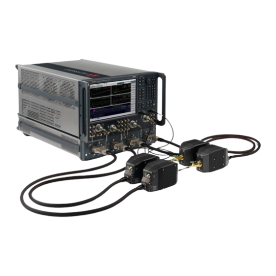
System Description N5290/1A Network Analyzer Millimeter-wave System N5290/1A Network Analyzer Millimeter-wave System The N5290/1A is a 2-port or 4-port vector network analyzer system (N5290/1A) with an extremely wide frequency range of 900 Hz to 110 GHz or 900 Hz to 120 GHz (N5291A). The N5290/1A uses the same 1.0 mm test port connections throughout its entire range of test frequencies. - Page 27 System Description N5290/1A Network Analyzer Millimeter-wave System Figure 2-1 N5290A 2-Port Test System – Coaxial Measurement Configuration (N5291A is similar.) N5222B with Option 205 (shown) N5227B and N5242/7B (Optional) N5292A 48" Cables (1.2 m) Millimeter-Head Controller N5293A millimeter-heads Keysight N5290/1A Installation Guide...
- Page 28 System Description N5290/1A Network Analyzer Millimeter-wave System Figure 2-2 N5290A System Options 2- 4 Keysight N5290/1A Installation Guide...
-
Page 29: System Description
System Description N5290/1A Network Analyzer Millimeter-wave System Figure 2-3 N5291A System Options System Description Introduction This section of this document describes the broadband millimeter-wave system using an N5292A Millimeter Head Controller. Banded millimeter-wave systems are made up of three types of major components: a PNA or PNA-X, a controller test set, and millimeter-wave heads. -
Page 30: Network Analyzer Requirements
System Description N5290/1A Network Analyzer Millimeter-wave System In this document the N5292A will be referred to as the test set. Figure 2-4 2-Port Banded Millimeter-wave Configuration (N5290/1A Option 201/2) Figure 2-5 4-Port Banded Millimeter-wave Configuration (N5290/1A Option 401/2/3) Network Analyzer Requirements The required options for PNA models are indicated in the “PNA Option(s)”... -
Page 31: System Configurations
If there is physical damage refer to “Contacting Keysight” on page 4-4. Keep the damaged shipping materials (if any) for inspection by the carrier and an Keysight Technologies representative. To reduce the chance of electrostatic discharge, follow all of the recommendations outlined in “Electrostatic Discharge Protection”... - Page 32 System Description N5290/1A Network Analyzer Millimeter-wave System Table 2-3 N5290A System Contents N5290A System Contents Option 201 Option 202 Option 401 Option 402 Option 403 N5222B 2-Port PNA, Option 205 N5227B 2-Port PNA, Option 205 N5242B 4-Port PNA-X, Option 425 N5242B 4-Port PNA-X, Option 425 with Option 029...
- Page 33 System Description N5290/1A Network Analyzer Millimeter-wave System Table 2-4 N5291A System Contents N5291A System Contents Option 201 Option 202 Option 401 Option 402 Option 403 N5222B 2-Port PNA, Option 205 N5227B 2-Port PNA, Option 205 N5242B 4-Port PNA-X, Option 425 N5242B 4-Port PNA-X, Option 425 with Option 029...
-
Page 34: N5290A And N5291A Millimeter System Interconnect Kits
System Description N5290/1A Network Analyzer Millimeter-wave System N5290A and N5291A Millimeter System Interconnect Kits IMPORTANT! The N5227B and N5247B interconnect kits contain 2.4 mm to 3.5 mm cables. It is important to connect the 2.4 mm end to the PNA and to connect the 3.5 mm end to the N5292A test set controller. - Page 35 System Description N5290/1A Network Analyzer Millimeter-wave System Table 2-6 N5290A/91A System Contents - Interconnect Kits: N5292-60012, N5292-60013, N5292-60014, N5292-60015, N5292-60016, and N5292-60017 (2 of 2) N5290A and N5291A Systems – Interconnect Kits Description Part Number Desig. N5292-60012 – N5292A-222 (2-Port Test and 2-Port VNA with 3.5 mm Ports) and N5292-422 (4-Port Test Set and 2-Port VNA with 3.5 mm Ports) Quick Start Poster (with links to Installation Guides &...
- Page 36 System Description N5290/1A Network Analyzer Millimeter-wave System Table 2-6 N5290A/91A System Contents - Interconnect Kits: N5292-60012, N5292-60013, N5292-60014, N5292-60015, N5292-60016, and N5292-60017 (2 of 2) N5290A and N5291A Systems – Interconnect Kits Description Part Number Desig. Upper lock foot, left, short N5240-20095 Cable assy-RF, SMA to SMA 16 in long –...
- Page 37 System Description N5290/1A Network Analyzer Millimeter-wave System Table 2-6 N5290A/91A System Contents - Interconnect Kits: N5292-60012, N5292-60013, N5292-60014, N5292-60015, N5292-60016, and N5292-60017 (2 of 2) N5290A and N5291A Systems – Interconnect Kits Description Part Number Desig. 3 dB pad (m) 50 GHz 2.4 mm SMA attached to network analyzer CPLR THRU 0955-2394 Cable assy, coaxial 50 ohm SMA (m) to 50 ohm SMA (m) - 12 in long 8121-2970...
- Page 38 System Description N5290/1A Network Analyzer Millimeter-wave System Table 2-6 N5290A/91A System Contents - Interconnect Kits: N5292-60012, N5292-60013, N5292-60014, N5292-60015, N5292-60016, and N5292-60017 (2 of 2) N5290A and N5291A Systems – Interconnect Kits Description Part Number Desig. N5292-60017 – N5292A-444 (4-Port Test Set and 4-Port VNA with 2.4 mm Ports) Quick Start Poster (with links to Installation Guides &...
-
Page 39: N5290A And N5291A Millimeter System Rackmount Kits
System Description N5290/1A Network Analyzer Millimeter-wave System N5290A and N5291A Millimeter System Rackmount Kits N5290/1A system rackmount kits are going to be available soon. Refer to “Contacting Keysight” on page 4-4. Use the table below to order rackmount kits. Table 2-7 Rackmount Front Handle Kits √... -
Page 40: N5292A Test Controller Description
System Description N5292A Test Controller Description N5292A Test Controller Description The N5292A-200 and N5292A-400 millimeter head controllers provide the test interface between the millimeter-wave test head modules and the PNA/PNA-X (PNA) series network analyzers. The millimeter-head controller, when used in conjunction with the millimeter-wave test head modules and the PNA, provides all of the functions of a full S-Parameter test set. -
Page 41: If Ref Out
System Description N5292A Test Controller Description IF Ref Out IF reference output connection provides direct access to the IF signal from the module and is accessed by changing a switch setting in the millimeter wave dialog. This enables you to connect and to measure higher frequency IF output signals. -
Page 42: Rear Panel Features
System Description N5292A Test Controller Description Rear Panel Features Figure 2-8 N5292A Option 200 (2-Port) and 400 (4-Port) – Rear Panel Features IF OUTPUTS – SMA (female) — D (from the test set to the analyzer’s IF D Input) — C (from the test set to the analyzer’s IF C Input) —... -
Page 43: Compatible Millimeter-Wave Modules
System Description Compatible Millimeter-Wave Modules Compatible Millimeter-Wave Modules Only Keysight N5293A and N5295A millimeter modules are compatible with the N5290A/1A Systems. If you have third party millimeter heads, and banded applications, refer to the N5292-90001 Self-configuration Installation Guide. Refer to “N5293/5A Millimeter-Wave Test Head Modules”... -
Page 44: N5293/5A Millimeter-Wave Test Head Modules
System Description Compatible Millimeter-Wave Modules Table 2-9 Available N529xA Millimeter-Wave Head Modules Model # Frequency Range N5293A 900 Hz to 110 GHz N5295A 900 Hz to 120 GHz N5293/5A Millimeter-Wave Test Head Modules 1, 2, 3, or 4 900 Hz -110 GHz or 900 Hz – 120 GHz millimeter-wave test head modules, in conjunction with the N5292A Option 200 or N5292A Option 400 millimeter head controller, is used to make reflection, transmission, or S-parameter measurements at millimeter-wave frequencies with the PNA. - Page 45 System Description Compatible Millimeter-Wave Modules Figure 2-10 N5293/5A Left and Right Frequency Extender Test Head Modules, Front View Integrated N5292A Controller Front Port Connector +20 dBm 50 VDC (1 mm) Figure 2-11 N5293/5A Left and Right Frequency Extender Test Head Modules, Back View Integrated N5292A Controller Sense Front Port Connector...
-
Page 46: Basic System Measurement Configurations
System Description Basic System Measurement Configurations Basic System Measurement Configurations The N5290/1A can be used in either of two basic configurations, depending on how the test ports are connected to the device under test (DUT): coaxial measurement configuration or wafer probe measurement configuration. Input power to the test ports must not exceed +20 dBm. - Page 47 System Description Basic System Measurement Configurations Figure 2-12 N5290/1A 4-Port Test System – Coaxial Measurement Configuration (N5291A is similar) N5247B (shown) N5222/7B and N5242B (Optional) N5292A 48" Cables (1.2 m) Millimeter-Head Controller N5293A millimeter-heads Keysight N5290/1A Installation Guide 2-23...
- Page 48 System Description Basic System Measurement Configurations 2- 24 Keysight N5290/1A Installation Guide...
-
Page 49: System Installation
Keysight N5290/1A PNA/PNA-X Series 2-Port and 4-Port Microwave Network Analyzer System Installation Guide System Installation IMPORTANT! A 85059B 1.0 mm Precision Calibration Kit and a 85059V 1.0 mm Precision Verification Kit are required to complete the installation of the N5290/1A Millimeter-wave Systems. -
Page 50: Getting Prepared
System Installation Getting Prepared Getting Prepared The N5290/1A contains extremely sensitive components that can be ruined if mishandled. Follow instructions carefully when making cable connections, especially wire harness connections. The person performing the work accepts responsibility for the full cost of the repair or replacement of damaged components. -
Page 51: Getting Assistance From Keysight
Getting Assistance from Keysight Getting Assistance from Keysight Installing this upgrade kit requires special skills and experience. Keysight will provide a customer engineer to assist you with the system’s installation. Refer “Keysight Technologies Customer Engineering” on page 3-4. Contacting Keysight Refer to “Keysight Support, Services, and Assistance”... -
Page 52: Receiving The System
If the shipping container is damaged or the packaging material shows signs of stress, notify the carrier as well as Keysight Technologies. Keep the shipping materials for the carrier’s inspection. Keysight Technologies will arrange for repair or replacement of damaged equipment without waiting for a claim settlement from the carrier. -
Page 53: Review The Principles Of Connector Care
System Installation Receiving the System Review the Principles of Connector Care Proper connector care and connection techniques are critical for accurate and repeatable measurements. Refer to Table 5-1 on page 5-3 for tips on connector care. Prior to making connections to your analyzer, carefully review the information about inspecting, cleaning, and gaging connectors. -
Page 54: Pna, Controller, And Test Head Module Interconnections
System Installation PNA, Controller, and Test Head Module Interconnections PNA, Controller, and Test Head Module Interconnections IMPORTANT! The N5227B and N5247B interconnect kits contain 2.4 mm to 3.5 mm cables. It is important to connect the 2.4 mm end to the PNA and to connect the 3.5 mm end to the N5292A test set controller. - Page 55 System Installation PNA, Controller, and Test Head Module Interconnections 1. On the PNA: Remove the feet from the bottom of the analyzer. 2. Remove the 2 lower standoffs from the rear panel on the analyzer. 3. Remove the top two standoffs from the rear panel on the test set. Figure 3-1 Rear Bottom Feet 4.
- Page 56 System Installation PNA, Controller, and Test Head Module Interconnections Figure 3-2 Install upper locking feet N5240-20092 and N5240-20095 using 0515-1619 screws (N5292-20092 and N5292-20095 are shorter in length and used on the N5227/47B). (i.e., N5240-20093 and N5240-20094 are similar, but longer in length and used on the N522B/42B.) Locking foot, long N5240-20095...
- Page 57 System Installation PNA, Controller, and Test Head Module Interconnections 5. On the N5292A: Install lower lock feet N5292-20012 and N5292-20013, using screw 0515-1619. Torque to 21 in-lbs. Refer to Figure 3-3 on page Figure 3-3 Install lower lock feet N5292-20012 and N5292-20013 using screws 0515-1619.
- Page 58 System Installation PNA, Controller, and Test Head Module Interconnections 7. Secure the analyzer’s lower locking feet (N5240-20092 and N5240-20095) to the test set’s upper locking feet (N5292-20012 and N5292-20013) using the spring–loaded screws on the locking feet. Refer to Figure 3-5.
- Page 59 System Installation PNA, Controller, and Test Head Module Interconnections 8. Remove semirigid cables from SOURCE OUT to CPLR THRU. Refer to Figure 3-6. 9. Connect 50 ohm terminations to CPLR THRU ports (1810-0818). Refer to Figure 3-6. Figure 3-6 Remove Semirigid Cables and Connect 50 termination to the CPLR THRU Ports Keysight N5290/1A Installation Guide 3-11...
- Page 60 System Installation PNA, Controller, and Test Head Module Interconnections 10. Install Interconnect Kit Semirigid Cables: IMPORTANT! The N5227B and N5247B interconnect kits contain 2.4 mm to 3.5 mm cables. It is important to connect the 2.4 mm end to the PNA and to connect the 3.5 mm end to the N5292A test set controller.
-
Page 61: N5290/1A Option 201 (Interconnect Kit N5292-60012)
System Installation PNA, Controller, and Test Head Module Interconnections N5290/1A Option 201 (Interconnect Kit N5292-60012) Refer to Figure 3-8. Figure 3-8 N5290/1A-201—(Interconnect Kit N5292-60012): Install semirigid cables (N5292-20006 and N5292-20009) and if not done, connect 50 ohm loads (1810-0118) to the front panel of the PNA and N5292A Keysight N5290/1A Installation Guide 3-13... -
Page 62: N5290/1A Option 202 (Interconnect Kit N5292-60013)
System Installation PNA, Controller, and Test Head Module Interconnections N5290/1A Option 202 (Interconnect Kit N5292-60013) IMPORTANT! The N5227B and N5247B interconnect kits contain 2.4 mm to 3.5 mm cables. It is important to connect the 2.4 mm end to the PNA and to connect the 3.5 mm end to the N5292A test set controller. -
Page 63: N5290/1A Option 401 Or N5290/1A Option 402-(Interconnect Kit N5292-60016)
System Installation PNA, Controller, and Test Head Module Interconnections N5290/1A Option 401 or N5290/1A Option 402—(Interconnect Kit N5292-60016) Figure 3-10 is used for a N5292-60016 interconnect kit. Figure 3-10 N5290/1A-401 or N5290/1A-402: Install semirigid cables (N5292-20006, N5292-20007, and N5292-20008) to the front panel of the PNA and N5292A. Option 442 is shown. -
Page 64: N5290/1A Option 403-(Interconnect Kit N5292-60017)
System Installation PNA, Controller, and Test Head Module Interconnections N5290/1A Option 403—(Interconnect Kit N5292-60017) IMPORTANT! The N5227B and N5247B interconnect kits contain 2.4 mm to 3.5 mm cables. It is important to connect the 2.4 mm end to the PNA and to connect the 3.5 mm end to the N5292A test set controller. -
Page 65: Rear Panel Cabling
System Installation PNA, Controller, and Test Head Module Interconnections Rear Panel Cabling Figure 3-12 on page 17 Figure 3-13 on page 18 shows how to install the cables for 2-port and 4-port systems. Torque all RF connections to 8 in-lbs (0.90 N.m) to insure proper connection. - Page 66 System Installation PNA, Controller, and Test Head Module Interconnections Figure 3-13 N5290A 2- and 4-Port Model Rear Panel Cabling Table 3-14 N5290A 2- and 4-Port Rear Panel Cabling LO OUT D/R2 C/R1 TEST SET I/O From: PNA LO IN TEST SET I/O To: N5292A 3- 18 Keysight N5290/1A Installation Guide...
-
Page 67: N5293/5A Modules Front Panel Cabling
System Installation PNA, Controller, and Test Head Module Interconnections N5293/5A Modules Front Panel Cabling IMPORTANT! In order to maintain compliance to the certificate of calibration it is recommended that the frequency extenders be connected to the corresponding test set ports per the Certificate of Calibration provided. IMPORTANT! Before connecting the millimeter-wave modules, verify that the test set and the power supplies (if used) are powered down. -
Page 68: N5292A Option 200 2-Port Cable Connections
System Installation PNA, Controller, and Test Head Module Interconnections N5292A Option 200 2–Port Cable Connections Figure 3-15 Cable Connections for Two Test Heads Module Figure 3-16 Cable Two Test Heads N5293/5AX03 to the N5292A. (Attach heads and torque cable screws to 8 in-lbs.) Torque cable screws to 8 in-lbs 3- 20 Keysight N5290/1A Installation Guide... -
Page 69: N5292A Option 400 4-Port Cable Connections
System Installation PNA, Controller, and Test Head Module Interconnections N5292A Option 400 4–Port Cable Connections Figure 3-17 Cable Connections for Four Test Heads Module Figure 3-18 Cable Four Test Heads N5293/5AX03 to the N5292A Torque cable screws to 8 in-lbs Keysight N5290/1A Installation Guide 3-21... -
Page 70: Initializing The N5290/1A Broadband System
System Installation Initializing the N5290/1A Broadband System Initializing the N5290/1A Broadband System After the N5290/1A Broadband System has been calibrated and verified at the factory, the PNA is reset back to "Standard PNA" mode to remove any artifact files from the test process. To change your PNA over to "N529xA Broadband" mode: 1. -
Page 71: Running The Installation Calibration
System Installation Running the Installation Calibration Running the Installation Calibration This installation calibration should be ran when you first install your system and whenever you make any changes to your system’s configuration. See also “Troubleshooting the N5293/5A Millimeter Modules” on page 3-26. - Page 72 System Installation Running the Installation Calibration 3. Press Installation Cal. In the dialog box opens, connect a load and press Measure. Refer to Figure 3-20. For best results use a load that extends to 125 GHz. Figure 3-20 Millimeter Installation Cal – Dialog Box 4.
- Page 73 System Installation Running the Installation Calibration 6. If prompted, repeat steps 3 through 5 for all of the other ports requiring calibration. Keysight N5290/1A Installation Guide 3-25...
-
Page 74: Troubleshooting The N5293/5A Millimeter Modules
System Installation Troubleshooting the N5293/5A Millimeter Modules Troubleshooting the N5293/5A Millimeter Modules The N5292A test set controller’s integrated front panel connectors contain optical sensors to ramp power up or down gradually when the N5293/5A millimeter modules are connected and disconnected to prevent damage. Refer Figure 3-23 Figure 3-24. -
Page 75: Performance Verification
Keysight N5290/1A PNA/PNA-X Series 2-Port and 4-Port Microwave Network Analyzer System Installaton Guide Performance Verification Information in This Chapter This chapter contains procedures to help you check, verify, and adjust your N5290/1A Millimeter-waveguide System. — The checks verify the operation of the instruments in your system. —... -
Page 76: Preliminary Checks
Performance Verification Preliminary Checks Preliminary Checks Preliminary checks include the following: — “System Operator’s Check” on page 4-3 — “System Verification” on page 4-7 Keysight N5290/1A Installation Guide... -
Page 77: Accessories Used In The Operator's Check
Performance Verification System Operator’s Check System Operator’s Check To achieve the maximum system stability, allow the analyzer to warm up for at least 15 minutes before performing the Operator’s Check. The operator’s check is a software driven test that checks the basic operation of the assemblies in all of the measurement port signal paths. - Page 78 Performance Verification System Operator’s Check 5. The result of the operator’s check will be shown as a PASS or FAIL next to each test (refer to Figure 4-1). The PNA Operator’s Check dialog box will look different for different PNA model numbers and installed options. Some of the tests are performed only if the appropriate options are installed in the PNA.
- Page 79 Performance Verification System Operator’s Check Figure 4-1 Operator’s Check Dialog Boxes Keysight N5290/1A Installation Guide...
-
Page 80: If The Operator's Check Fails
Performance Verification If the Operator’s Check Fails If the Operator’s Check Fails 1. Clean the test ports, shorts, and adapters. Torque to specification. Repeat the check. 2. If the check still fails, suspect a faulty component. Refer to “Contacting Keysight” on page 4-4. -
Page 81: System Verification
Performance Verification System Verification System Verification System verification is used to verify system-level, error-corrected uncertainty limits for network analyzer system measurements. The verification procedure is automated and is contained in the firmware of the analyzer. The device data provided with the verification kit has a traceable path to a national standard. -
Page 82: Measurement Traceability
Performance Verification System Verification in the measurement system after calibration. The systematic errors are: — directivity, — source match, — load match, — reflection and transmission frequency tracking, and — isolation (crosstalk). The random errors include: — noise, — drift, —... - Page 83 Performance Verification System Verification Figure 4-2 Traceability Path for Calibration and Verification Standard Keysight N5290/1A Installation Guide...
-
Page 84: Performing System Verification
Performance Verification System Verification Performing System Verification The following verification procedure is automated by the analyzer firmware. The process for the verification is: — connect cables to the analyzer test ports — perform a calibration or recall a recent calibration —... -
Page 85: Kit Substitution
Performance Verification System Verification performance is a significant contributor to the system performance, cables of lower performance will increase the uncertainty of your measurement. It is highly recommended that the test port cables be regularly tested. If the system verification is performed with a non-Keysight cable, ensure that the cable meets or exceeds the specifications for the test cable specified in the previous table, “Equipment Used in the System Verification Procedure.”... -
Page 86: If The System Fails The Verification Test
Performance Verification System Verification 5. Under Outputs, select the desired output(s). Refer to Figure 4-3. — Print Tabular Data: Prints the verification data in tabular form which includes measured data and uncertainty limits. For an example, refer to Figure 4-5 on page 4-14. -
Page 87: Interpreting The Verification Results
Performance Verification System Verification 3. Measure the device again. 4. If the analyzer still fails the test, contact Keysight. Refer to “Contacting Keysight” on page 4-4. 5. Refer to Figure 4-4 for additional troubleshooting steps. Figure 4-4 System Verification Failure Flowchart Interpreting the Verification Results Figure 4-5 shows an example of typical verification results with Print Tabular... - Page 88 Performance Verification System Verification Each S-parameter measurement result is printed with frequency tested, lower and upper limit lines, the measured data, and the result of the test. Figure 4-5 Example of Printed Tabular Verification Results 4-14 Keysight N5290/1A Installation Guide...
- Page 89 Performance Verification System Verification Figure 4-6 shows an example of typical verification results with Print Graphs selected in the Printer Output area of the System Verification dialog box. The printed graphical results show the following: — the name of the device measured —...
-
Page 90: If The System Verification Fails
Performance Verification If the System Verification Fails If the System Verification Fails If the System Verification fails, refer to “Contacting Keysight” on page 4-4. 4-16 Keysight N5290/1A Installation Guide... -
Page 91: Maintenance And Support
Keysight N5290/1A PNA/PNA-X Series 2-Port and 4-Port Microwave Network Analyzer System Installaton Guide Maintenance and Support Information in This Chapter Chapter Five at-a-Glance Section Title Summary of Content “Maintenance” on page 4-2 How to take care of your system electrically and your system’s connector care. -
Page 92: Maintenance
Refer to the calibration kit documentation for detailed connector care information. For course numbers about additional connector care instruction, contact Keysight Technologies. Refer to “Contacting Keysight” on page 4-4. 1. Use isopropyl alcohol only in a well-ventilated area. Allow all residual alcohol mois- ture to evaporate, and the fumes to dissipate, prior to assembling waveguide inter- faces. - Page 93 Maintenance and Support Maintenance Table 5-1 Connector Care Quick Reference Guide Handling and Storage — Keep connectors clean Do Not — Touch mating-plane surfaces — Extend sleeve or connector nut — Set connectors contact-end down — Use plastic end-caps during storage —...
-
Page 94: Keysight Support, Services, And Assistance
Maintenance and Support Keysight Support, Services, and Assistance Keysight Support, Services, and Assistance Information on the following topics is included in this section. — “Service and Support Options” — “Contacting Keysight” — “Shipping an Item to Keysight for Service or Repair” Service and Support Options The N5290/1A system has a one-year service warranty which covers troubleshooting the system to an individual instrument, device, or cable. -
Page 95: Shipping An Item To Keysight For Service Or Repair
Keysight for repair. If you wish to send an item from your system to Keysight Technologies for service or repair: — Contact Keysight to open a service order. Refer to “Contacting... - Page 96 This information is subject to change without notice. © Keysight Technologies 2009-2017 Edition 1, December 2017 N5292-90002 www.keysight.com...
Need help?
Do you have a question about the PNA Series and is the answer not in the manual?
Questions and answers