Sign In
Upload
Manuals
Brands
Keysight Technologies Manuals
Measuring Instruments
N5247B
Keysight Technologies N5247B Manuals
Manuals and User Guides for Keysight Technologies N5247B. We have
4
Keysight Technologies N5247B manuals available for free PDF download: Service Manual, Installation Note, Installation Notes
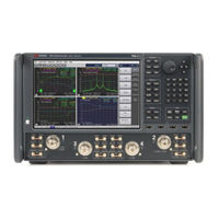
Keysight Technologies N5247B Service Manual (566 pages)
2-Port and 4-Port PNA-X Microwave Network Analyzer
Brand:
Keysight Technologies
| Category:
Measuring Instruments
| Size: 17 MB
Table of Contents
Table of Contents
3
Safety and Regulatory Information
11
Information in this Chapter
11
Chapter One At-A-Glance
11
Safety Symbols
12
General Safety Considerations
13
Safety Earth Ground
13
Before Applying Power
13
Servicing
15
Electrostatic Discharge Protection
17
Regulatory Information
19
Instrument Markings
19
Lithium Battery Disposal
22
General Product Information
23
Information in this Chapter
23
Chapter Two At-A-Glance
23
Maintenance
24
Physical Maintenance
24
Electrical Maintenance
24
Analyzer Options, Accessories, and Upgrades Available
25
Pulse I/O Adapter-N1966A
25
Required Service Test Equipment
26
Keysight Support, Services, and Assistance
29
Service and Support Options
29
Contacting Keysight
29
Shipping Your Analyzer to Keysight for Service or Repair
30
Tests and Adjustments
31
Information in this Chapter
31
Conventions Used for Hardkeys, Softkeys, and Menu Items
31
Chapter Three At-A-Glance
31
Before You Begin
34
Verify the Operating Environment
34
Protect against Electrostatic Discharge (ESD)
34
Allow the Analyzer to Warm up
35
Review the Principles of Connector Care
35
About System Verification and Performance Tests
37
System Specifications
37
Instrument Specifications
38
System Verification Procedure
38
Performance Tests
38
Certificate of Calibration
39
ANSI/NCSL Z540.3-2006 and ISO/IEC 17025 Verification
40
Non-Standards Compliant Verification
41
Preliminary Checks
42
The Operator's Check
42
The Test Port Cable Checks
45
System Verification
52
What the System Verification Verifies
52
Measurement Uncertainty
52
Measurement Traceability
53
Performing System Verification
54
Performance Tests
62
Source Power Accuracy Test
62
Source Maximum Power Output Test
63
Source Power Linearity Test
64
Frequency Accuracy Test
65
Trace Noise Test
66
Receiver Compression Test
66
Noise Floor Test
68
Calibration Coefficients Test
69
Dynamic Accuracy Test - Version 1
70
Dynamic Accuracy at Low Frequency (Available with LFE Option 205/220/420/425)
73
DC Continuity Test the LFE Board and Test Ports (Available with LFE Option 205/220/420/425)
75
Receiver Noise Figure Test
75
Noise State Calibration Coefficients
76
Noise Jitter Test
76
Noise Receiver Linearity Test
77
Noise Receiver Compression Test
78
DC Continuity Test the LFE Board and Test Ports (Available with Low Frequency Extension (LFE) Installed Option 205/425)
83
Adjustments
84
Touchscreen Adjustment and Verification
84
10 Mhz Frequency Reference Adjustment
85
Synthesizer Bandwidth Adjustment
86
Source Adjustment
86
IF Gain Adjustment
88
Receiver Characterization
88
Receiver Adjustment
88
EE Default Adjustment
90
IF Response Adjustment (Available Only with Option S93093/4A/B and or S93900/1/2/4/5/7A/B Installed)
91
LFE Receiver Adjustment (Option 425)
91
Noise Figure Adjustment (Available with Option 029 with S93029A/B Installed)
92
Troubleshooting
97
Information in this Chapter
97
Chapter Four At-A-Glance
98
Conventions Used for Hardkeys, Softkeys, and Menu Items
99
Operating the Analyzer with Covers Removed
100
Protect against Electrostatic Discharge (ESD)
100
Assembly Replacement Sequence
100
Getting Started with Troubleshooting
101
Check the Basics
101
Troubleshooting Organization
101
Power up Troubleshooting
103
Power Supply Check
104
Troubleshooting LCD Display Problems
109
Front Panel Troubleshooting
111
Front Panel Keypad and RPG Test
111
A3 Display Test
114
Checking the A2 USB Board
115
A1 Front Panel Interface Board
116
Rear Panel Troubleshooting
118
Checking the USB Ports
118
Checking the CONTROLLER Port
118
LAN Troubleshooting
119
Measurement System Troubleshooting
125
Before You Begin-Consider: Where Do You See a Problem
125
Verifying the A, B, C, D, and R Traces (Standard S-Parameter Mode)
126
Where to Begin Troubleshooting
128
Checking the Source Group
131
Checking the Signal Separation Group
143
Checking the Receiver Group
148
Instrument Simplified Block Diagrams - LFE
152
2-Port N5290A System Block Diagram (201 and 205)
152
2-Port N5290A System Block Diagram (202 and 205)
153
4-Port N5290A System Block Diagram (401)
154
Instrument Block Diagrams - 2-Port (Sheet 1), Non-LFE and Non-DDS
158
Synthesizers)
158
Instrument Block Diagrams - 2-Port (Sheet 2), Non-LFE and DDS
160
Assemblies)
160
Microwave PNA-X, N5247B - 2-Port, Non-LFE and DDS
160
Instrument Block Diagrams - 4-Port (Sheet 3), Non-LFE and Non-DDS (Version 6
162
Synthesizers)
162
Microwave PNA-X, N5247B - 4-Port, LFE and Non-DDS (Version 6 Synthesizers)
164
Instrument Block Diagrams - 4-Port (Sheet 5), Non-LFE and DDS
166
Assemblies)
166
Microwave PNA-X, N5247B - 4-Port, Non-LFE and DDS
166
Assemblies)
168
Instrument Block Diagrams - 4-Port (Sheet 6), LFE and DDS
168
Microwave PNA-X, N5247B - 4-Port, LFE and DDS (Version 7 Synthesizer Assemblies)
168
Theory of Operation
171
Information in this Chapter
171
Chapter Five At-A-Glance
171
Network Analyzer System Operation
173
Functional Groups of the Network Analyzer
176
Synthesized Source Group Operation
180
Basic Operation
181
A4, A15, and A17 13.5 Ghz Synthesizer Boards (S/N Prefixes <6021 Only)
195
A5 and A10 26.5 Ghz Source Boards
197
A7, A8, A12, and A13 40 Ghz Doubler Boards
197
A60, A61, A62, and A63 70 Ghz Doubler Boards
198
A25 Multiplier/Amplifier 26.5 Board (HMA26.5)
198
A14 Frequency Reference Board (S/N Prefixes <6021 Only)
198
A23 Test Set Motherboard
199
A70 4-Port and A75 2-Port Low Frequency Extension (LFE) Board
202
Signal Separation Group Operation
216
Configurable Test Set
216
A29-A32 Reference Couplers
217
A33-A36 Test Port Couplers
217
A38-A41 50-Db Source Step Attenuators and A42-A45 Bias Tees (Optional)
221
A50-A53 Mechanical Switches and A54 Combiner (Optional)
221
Receiver Group Operation
223
A46-A49 50-Db Receiver Step Attenuators (Optional)
223
A37 Reference Mixer Switch
223
A27 and A28 Mixer Bricks
223
A24 if Multiplexer Board
224
A16 SPAM Board (Analog Description)
225
Digital Processing and Digital Control Group Operation
229
Front Panel Subgroup
231
Data Acquisition and Processing Subgroup
232
Power Supply Group Operation
234
Noise Measurement Group Operation (Option 029)
235
A56 Test Port 1 Option 029 Switch
235
A64 Test Port 1 Option 029 Tuner
235
A57 Test Port 2 Option 029 Switch
235
A59 Noise Downconverter
235
A9 Noise Receiver Board
236
Replaceable Parts
239
Information in this Chapter
239
Chapter Six At-A-Glance
239
Ordering Information
240
Assembly Replacement Sequence
241
Rebuilt-Exchange Assemblies
242
Replaceable Parts Listings
244
Front-Panel Assembly, Front Side, All Options
250
Front-Panel Assembly, Back Side, All Options
252
Top Assemblies and Cables, All Options, Serial Number Prefixes <6021
256
Top Assemblies and Cables, All Options, Serial Number Prefixes ≥6021
262
2-Port Configurations, Serial Number Prefixes <6021
269
4-Port Configuration, Serial Number Prefixes <6021
322
4-Port Configurations, Serial Number Prefix ≥6021
374
Rear-Panel Assembly, All Options
427
Fan Assemblies, All Options
430
Top Hardware and Miscellaneous Parts, All Options
432
Bottom Hardware and Miscellaneous Parts
434
Internal Hardware and Miscellaneous Parts, All Options
438
External Hardware and Miscellaneous Parts, All Options
440
Miscellaneous Part Numbers
442
Repair and Replacement Procedures
445
Information in this Chapter
445
Chapter Seven At-A-Glance
445
Personal Safety Warnings
446
Electrostatic Discharge (ESD) Protection
447
Removal and Replacement Procedures
448
Removing the Covers
450
Removing and Replacing the Front Panel Assembly
452
Removing and Replacing the A1-A3 and Other Front Panel Subassemblies
454
Removing and Replacing the A4-A17 Boards
462
Removing and Replacing the A18 System Motherboard
465
Removing and Replacing the A19 Midplane Board
468
Removing and Replacing the A20 Power Supply Assembly
470
Removing and Replacing the A21 CPU Board Assembly
472
Removing and Replacing the A22 GPIB Board
474
Removing and Replacing the A23 Test Set Motherboard
476
Removing and Replacing the A24 if Multiplexer Board
478
Removing and Replacing the A25 HMA26.5
480
Verify the Model/Version of HMA26.5 Installed
481
Removing and Replacing the A26 Splitter
483
Removing and Replacing the A27 and A28 Mixer Bricks
485
Removing and Replacing the A33-A36 Test Port Couplers
490
Removing and Replacing the A37 Reference Mixer Switch
492
Attenuators
495
Removing and Replacing the A42-A45 Bias Tees
498
Removing and Replacing the A50-A53 Bypass Switches and the A54 Combiner
501
Removing and Replacing the A55 Solid State Drive (SSD)
504
Removing and Replacing the A60-A63 70 Ghz Doublers
506
Removing and Replacing the A56 Port 1 Noise Bypass Switch (Option 029)
508
Removing and Replacing the A57 Port 2 Noise Bypass Switch (Option 029)
510
Removing and Replacing the A59 Noise Receiver (Downconverter) - (Option 029)
512
Removing and Replacing the A64 Tuner (Option 029)
514
Removing and Replacing the A70 or A75 Low Frequency Extension (LFE) Board
516
Removing and Replacing the A71-A74 Bias Tee Combiners
523
Removing and Replacing the Rear Panel
528
Removing and Replacing the Front Panel LED Boards
530
Removing and Replacing the Fans
532
Removing and Replacing the Lithium Battery
534
Post-Repair Procedures
536
Resetting the Mechanical Counter
545
EEPROM Backup
546
General Purpose Maintenance Procedures
549
Information in this Chapter
549
Chapter Eight At-A-Glance
549
Conventions Used for Hardkeys, Softkeys, and Menu Items
549
Error Terms
550
Using Error Terms as a Diagnostic Tool
550
Performing Measurement Calibration
551
Using Flowgraphs to Identify Error Terms
551
Accessing Error Terms
554
Error Term Data
556
Keysight License Manager
559
Accessing the Keysight License Manager
559
Software Entitlement Certificate
559
Enabling or Removing Options
560
Repairing and Recovering Option Data
561
Installing or Changing a Serial Number
561
Firmware Upgrades
562
How to Check the Current Firmware Version
562
Downloading from the Internet
562
Operating System Recovery
563
Recovering from Solid State Drive Problems
563
Correction Constants
564
Storing Correction Constants
564
Advertisement
Keysight Technologies N5247B Service Manual (226 pages)
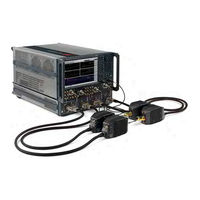
2-Port and 4-Port Microwave Network Analyzer System (900 Hz - 110 GHz / 900 Hz - 120 GHz)
Brand:
Keysight Technologies
| Category:
Measuring Instruments
| Size: 6 MB
Table of Contents
Table of Contents
5
1 Safety and Regulatory Information
11
Information in this Chapter
11
Chapter One At-A-Glance
11
Safety Symbols
12
General Safety Considerations
13
Safety Earth Ground
13
Before Applying Power
13
Servicing
15
Electrostatic Discharge Protection
17
ESD Equipment Required for the Installation
18
Regulatory Information
19
Instrument Markings
19
Lithium Battery Disposal
20
EMC and Safety Information
20
N5292A Test Set Equipment Ratings
22
Environmental Requirements
23
System Heating and Cooling
24
Required Conditions for Accuracy Enhanced Measurement
24
Space Requirements
25
N5290/1A System Weight and Dimensions
25
Component Weight and Dimensions
25
Site Preparation
27
Power Requirements
27
2 General Product Information
29
Information in this Chapter
29
Chapter Two At-A-Glance
29
N5290/1A System Options, Accessories, and Upgrades Available
31
Required Service Test Equipment
31
Keysight Support, Services, and Assistance
34
Service and Support Options
34
Contacting Keysight
35
Shipping an Item to Keysight for Service or Repair
35
Product Selection and Configuration Assistance, Education and Training
36
3 System Tests and Adjustments
37
Information in this Chapter
37
Chapter Three At-A-Glance
38
Before You Begin
39
Verify the Operating Environment
39
Torquing Connections
40
Long Term Storage of Test Results
40
Protect against Electrostatic Discharge (ESD)
41
Review the Principles of Connector Care
41
ANSI/NCSL Z540.3-2006 and ISO/IEC 17025 Verification
43
Non-Standards Compliant Verification
43
The N5290/1A Millimeter Test System Preliminary Check
43
N5290/1A Incoming Electrical Inspection
44
N5292A Functional Verification Procedure
52
Initial Setup for the N5292A Test Set Functional Verification
52
Performing the N5292A Test Set Functional Verification
59
N5290/1A Millimeter-Wave Test System Operator's Check
77
Performing the N5290/1 a System Operator's Check
77
If the N5290/1A Operator's Check Fails
80
Test Management Environment (TME) Performance Tests (N5290/1 a Millimeter System Only)
81
Guidelines for Ordering Power-Sensor Calibration Service
81
Adjustments
83
LO Adjustment for MM Mode
85
IF Gain Adj for MM Mode
85
Source and Receiver Adj
85
Receiver Characterization
85
IF Response Adj. for MM Mode
85
4 N5290/91A Troubleshooting
87
Information in this Chapter
87
Chapter Four At-A-Glance
88
Getting Started with Troubleshooting
89
Troubleshooting Organization
89
N5290/1A Millimeter-Wave System Troubleshooting
91
N5292A Test Controller Troubleshooting
92
Power Supplies and Fans
92
No DC Power for Millimeter-Wave Modules
94
Procedure for Identifying a Faulty Millimeter Head
94
Verifying the A5 Test Set Motherboard (TSMB)
94
Verifying the A1 Power Supply
103
Verifying the A2 LOPA, A3 LODA, and A4 Phase Compensation Boards
108
Head Stability Check
111
Front Panel Active LED
113
RF out Failures
113
LO out Failure
113
REF if or Test if
114
Test Set Diagrams and Graphics
115
5 Theory of Operation
119
Information in this Chapter
119
Chapter Seven At-A-Glance
120
Theory of Operation
121
Overview
121
LO Behavior Without LFE (Low Frequency Extension)
121
LO Behavior with Low Frequency Extension (LFE) Operation
121
10 Mhz to 19 Ghz Operation
122
DC Power
122
Overview - N5292A Test Set
123
System Level Block Diagrams
124
6 Replaceable Parts
129
Information in this Chapter
130
Chapter Six At-A-Glance
131
Ordering Information
132
Assembly Replacement Sequence
133
Replaceable Parts Listings
134
Front Panel Assembly, Front Side, All Options
137
Front Panel Assembly, Back Side, All Options
141
Top Assemblies and Cables, All Options
146
Top Assemblies, All Options
146
Top Cables, All Cables, All Options
147
Bottom Assemblies and Cables, All Options by Option Set
149
N5292A 2-Port Configuration, Option 200
149
N5292A 4-Port Configuration, Option 400
154
Rear-Panel Assembly, All Options
160
Fan Assemblies, All Options
161
Top Hardware and Miscellaneous Parts, All Options
163
Bottom Hardware and Miscellaneous Parts, All Options
164
Internal Hardware and Miscellaneous Parts, All Options
168
External Hardware and Miscellaneous Parts, All Options
170
Miscellaneous Part Numbers
171
Replaceable Parts
173
7 Repair and Replacement Procedures
177
Information in this Chapter
177
Chapter Seven At-A-Glance
178
Personal Safety Warnings
179
Electrostatic Discharge (ESD) Protection
180
Removal and Replacement Procedures
181
Removing the N5292A Option 200/400 from the System
182
Removing the Cover
184
Removing and Replacing the Front Panel and Subpanel Assemblies
186
Removing and Replacing the A2-A4 Boards
190
Removing and Replacing the A5 Test-Set Motherboard
196
Removing and Replacing the A1 Power Supply Assembly
200
Removing and Replacing the Rear Panel
202
Removing and Replacing the Front Panel Power Switch Board
204
Removing and Replacing the Subpanel PCA Sensor Boards
205
Removing and Replacing the Front Panel Integrated Connectors/Cables
207
Removing and Replacing the Fans
209
Post-Repair Procedures
212
8 General Purpose Maintenance Procedures
215
Information in this Chapter
216
Chapter Eight At-A-Glance
216
Maintenance
217
Physical Maintenance
217
Electrical Maintenance
217
Error Terms
217
Keysight License Manager
218
Accessing the Keysight License Manager
218
Software Entitlement Certificate
218
Enabling or Removing Options
219
Repairing and Recovering Option Data
220
Installing or Changing a Serial Number
220
Firmware Upgrades
221
How to Check the Current Firmware Version
221
Downloading from the Internet
221
Operating System Recovery
222
Keysight Technologies N5247B Installation Note (70 pages)
2-Port/4-Port , PNA-X Upgrade Kit
Brand:
Keysight Technologies
| Category:
Measuring Instruments
| Size: 2 MB
Table of Contents
Contents of Upgrade Kit N5242-60117 for N5241Au-690 (N5241B)
13
Lower Front Panel Overlay, 2-Port (N5241/2/9B Option
12
Table of Contents
13
N5242
19
N5242
20
N5242
21
N5242
22
N5242
23
N5242
24
N5242
25
Step 1. Copy All Unique Files to an External Disk Drive
26
N5242
26
Step 2. Update Windows 7 os Instruments with A.10.40 or above
27
N5242
27
Step 3. Verify Windows 7 os with New A.10.40.00 Firmware or Greater
28
N5240
28
Step 4. Remove the Outer Covers
29
N5240
29
Step 5. Remove the Power Supply Cover
30
Step 6. Install the *New* Version 7 CPU Assembly
30
N5240
30
Step 7. Install the Service Center's N5242-60133 Solid-State Disk Drive Assembly (SSDA) with A.10.40 or Above-(Windows XP os Only)
31
N5242
31
Step 8. Install the *New* Power Supply Cover
32
N5242
32
Step 9. Power up Your Instrument with the *New* Version 7 CPU and Allow Windows 7 to Stabilize
33
Step 10. Remove the Front Panel Assembly
34
Step 11. Inspect and if Required, Replace Front Subpanel
35
N5221
36
Step 12. if Required, Rotate the LED Boards and Replace the LED Bias Cables (N5244/5A Only)
36
Step 13. Inspect or Modify Midplane Board (W1312-63095 to a W1312-63376)
37
N5242
37
N5240
38
Step 14. Install the Dress Panel on the New Front Panel Assembly
39
N5240
39
Step 15. Install the New Overlays on the New Front Panel Assembly
40
N5242
40
Step 16. Install the New Front Panel Assembly and the Lower Overlay
41
N5247
41
N5240
42
N5242
43
N5242
44
N5242
45
Step 17. Install New Version SPAM V, Synth, if Multiplexer, and Test Set Mother Boards (if Necessary)
45
N5245
46
Step 18. Install the New Handler I/O Cable
46
N5245
47
Step 19. Install the *NEW* N5242-60135 Solid-State Disk Drive Assembly (SSDA) from the Upgrade Kit
47
N5245
48
Step 20. Reboot the Instrument
48
N5245
49
Step 21. Reinstall the Outer Covers
49
N5242
50
Step 22. Install Option N52Xxau-690
50
N5245
51
N5245
52
Step 23. Changing Your Pna's Computer Name from an a Model to a B Model
52
N5240
53
Step 24. Install and Verify Multiple License Files
53
N5240
54
Step 25. Verify the PNA Analyzer Program Is Running with the Correct Options
54
N5240
55
Step 26. Copy the Unique Files Back to the Analyzer's SSD
55
N5242
56
Step 27. Perform Post-Upgrade Adjustments and Calibration
56
N5242
57
Step 28. Prepare the PNA for the User
57
N5247
58
N5240
59
N5240
60
N5242
61
N5247
62
N5240
63
W1312
64
N5242
65
N5242
66
N5247
67
N5247
68
N5247
69
N5247
70
Advertisement
Keysight Technologies N5247B Installation Notes (42 pages)
4-Port PNA Direct Digital Synthesizer DDS For Version 7 Dual-Source Synthesizer Upgrade Kit
Brand:
Keysight Technologies
| Category:
Measuring Instruments
| Size: 2 MB
Table of Contents
Safety Notices
2
Getting Assistance from Keysight
4
Contacting Keysight
4
Getting Prepared
5
Tools Required for the Installation
7
Table of Contents
10
Overview of the Installation Procedure
10
Step 1. Verify PNA and Erase Flash
11
Step 2. Remove the Inner and Outer Covers
13
Step 3. Remove some Cables (All Models) and some Bottom Assemblies (Options 405, 420, and 425 Only)
13
Step 4. Remove some Top Cables
17
Step 5. Remove the Left and Right Inner Bracket's #4 Card Guides
19
Step 6. Install the Center Bracket
20
Step 7. Reinstall Bottom Cables
21
Step 8. Reinstall Top Assemblies Reinstall the A5 through A16
22
Direct Digital Synthesis (DDS) Assembly) and Cables
22
Step 9. Install *NEW* A15 Direct Digital Synthesizer (DDS) Assembly"
23
Step 10. Install *NEW* and Reused Direct Digital Synthesis (DDS) Assembly Cables
25
Step 11. Route Gray Cables
30
Step 12. Add Back Plate and Cable to Rear Panel (Option 422/423 with and Without 029 Only)
32
Step 13. Install "SRC3 J13" Label on Rear Panel (Option 422/423 with and Without Option 029 Only)
34
Step 14. Remove and Replace the A55 Solid State Drive (SSD)
34
Step 15. Boot the Instrument
35
Step 16. Reinstall the Inner and Outer Covers
35
Step 17. Verify the PNA Analyzer Program Is Running with the Correct Options
35
Step 18. Perform Post-Upgrade Adjustments and Calibration
36
Advertisement
Related Products
Keysight Technologies N5247A
Keysight Technologies PNA-X N5242A
Keysight Technologies N5241B
Keysight Technologies N5241AU-922
Keysight Technologies N5242-60102
Keysight Technologies N5245-60106
Keysight Technologies N5245-60133
Keysight Technologies N5245BU-679
Keysight Technologies N5244BU-679
Keysight Technologies N5249BU-617
Keysight Technologies Categories
Measuring Instruments
Test Equipment
Control Unit
Portable Generator
Power Supply
More Keysight Technologies Manuals
Login
Sign In
OR
Sign in with Facebook
Sign in with Google
Upload manual
Upload from disk
Upload from URL