Chapters
Table of Contents
Troubleshooting

Related Manuals for Toro Reelmaster 5410 Series


Summary of Contents for Toro Reelmaster 5410 Series
- Page 1 Form No. 15216SL Rev C Reelmaster ® 5410/5510/5610 Series (Models with InfoCenter Display) © 2019—The Toro® Company Original Instructions (EN) 8111 Lyndale Avenue South Contact us at www.Toro.com. Bloomington, MN 55420 All Rights Reserved...
- Page 2 Revision History Revision Date Description – Initial issue. 03/2015 01/2018 Incorporated 5610-D Model 03679 04/2018 Revised bedknife installation procedure and painted/aluminum side plate cutting unit information. 03/2019 Updated Chassis chapter. Revision History Page 2 Reelmaster ® 5410/5510/5610 Series 15216SL Rev C...
- Page 3 Reader Comments The Toro Company Technical Assistance Center maintains a continuous effort to improve the quality and usefulness of its publications. To do this effectively, we encourage user feedback. Please comment on the completeness, accuracy, organization, usability, and readability of this manual by an e-mail servicemanuals@toro.com...
- Page 4 NOTES: NOTES: Page 4 Reelmaster ® 5410/5510/5610 Series 15216SL Rev C...
- Page 5 Operator’s Manuals and Parts Catalog for your machine. Additional copies of the Operator’s Manuals and Parts Catalogs are available at www.toro.com. The Toro Company reserves the right to change the product specifications or this publication without notice. DANGER This safety symbol means danger.
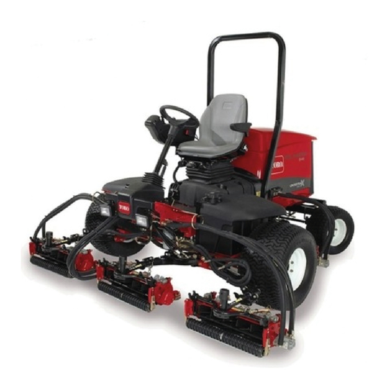
- Page 6 g230519 Figure 1 Product Variations Machine Model Engine Traction Reel Drive Cutting Unit Name Numbers Drive 5410 03675 Kubota non-Tier4 5 inch cutting compliant diesel engine units and smaller 5410-G 03608 Kubota gasoline engine Smaller displacement displacement 03673 reel motors gear pump without 5410-D...
- Page 7 Service Procedure Icons The following icons appear throughout this Service Manual to bring attention to specific important details of a service procedure. Critical Process This icon is used to highlight: • installing safety equipment (shields, guards, seat belts, brakes and R.O.P.S. components) that may have been removed •...
-
Page 8: Table Of Contents
Table of Contents Preface ........................ 5 Chapter 1: Safety .................... 1–1 Safety Instructions ..................1–2 Jacking Instructions ..................1–6 Safety and Instructional Decals ..............1–7 Chapter 2: Specifications and Maintenance ............ 2–1 Specifications ....................2–2 Torque Specifications ................... 2–5 Shop Supplies .................... 2–10 Special Tools .................... - Page 9 Adjustments ....................10–4 Service and Repairs ................... 10–6 Chapter 11: Universal Groomer (Optional) ............ 11–1 General Information ................... 11–2 Troubleshooting ..................11–3 Service and Repairs ................... 11–4 Appendix A ......................A–1 Electrical Drawing Designations..............A–2 Hydraulic Schematic-5410/5410-D ...............A–3 Hydraulic Schematic-5510/5510-D/5610 ............A–4 Hydraulic Schematic-5610-D ................A–5 Electrical Schematic-5410/5510/5610 (Models with Kubota Diesel Engine) ......................A–6 Electrical Schematic-5410-D/5510-D (Models with Yanmar Diesel...
- Page 10 Preface Page 10 Reelmaster ® 5410/5510/5610 Series 15216SL Rev C...
-
Page 11: Chapter 1: Safety
Chapter 1 Safety Table of Contents Safety Instructions ..........................1–2 Supervisor’s Responsibilities ......................1–2 Before Operating the Machine ......................1–2 While Operating the Machine ......................1–3 Maintenance and Service........................1–4 Jacking Instructions ..........................1–6 Raising the Front of the Machine......................1–6 Raising the Rear of the Machine ...................... -
Page 12: Safety Instructions
Operator’s Training DVD before starting and operating the machine. Become familiar with the controls and know how to stop the machine and engine quickly. Additional copies of the Operator’s Manuals are available at www.toro.com. • Keep all the shields, safety devices, and decals in place. If a shield, safety device, or decal is illegible or damaged, repair or replace it before operating the machine. - Page 13 While Operating the Machine • Sit on the seat when starting and operating the machine. • Anytime you park the machine (short or long term), lower the cutting decks to the ground. IMPORTANT When you lower the cutting deck to the ground, the pressure from the hydraulic lift circuit releases and prevents the cutting deck from accidentally lowering.
- Page 14 Jacking Instructions (page 1–6). • If major repairs are necessary, contact your Authorized Toro Distributor. • When welding on the machine, disconnect all the battery cables to prevent damage to the machine electronic equipment. Disconnect the negative Safety: Safety Instructions Page 1–4...
- Page 15 Maintenance and Service (continued) battery cable and then the positive cable. Disconnect the engine wire harness from the Toro Electronic Controller (TEC), disconnect and remove the engine ECU, and disconnect the terminal connector from the alternator, attach the welder ground cable not more than 610 mm (2 ft) from the welding location.
-
Page 16: Jacking Instructions
Jacking Instructions CAUTION Failing to properly support the machine with appropriate jack stands can cause the machine to move or fall and can result in personal injury. When changing the attachments, tires, or performing other services, do the following steps: •... -
Page 17: Safety And Instructional Decals
Numerous safety and instruction decals are affixed to the traction unit and cutting units of your Reelmaster. If any decal becomes illegible or damaged, install a new decal. Decal part numbers are listed in your Parts Catalog. Order replacement decals from Authorized Toro Distributor. Reelmaster ®... - Page 18 Safety: Safety and Instructional Decals Page 1–8 Reelmaster ® 5410/5510/5610 Series 15216SL Rev C...
-
Page 19: Chapter 2: Specifications And Maintenance
Chapter 2 Specifications and Maintenance Table of Contents Specifications ............................2–2 Decimal and Millimeter Equivalents ....................2–2 U.S. to Metric Conversions ........................ 2–4 Torque Specifications ........................... 2–5 Identifying the Fastener........................2–5 Fasteners with a Locking Feature ...................... 2–5 Calculating the Torque Values When Using a Drive-Adapter Wrench ..........2–6 Standard Torque for Dry, Zinc Plated, and Steel Fasteners (Inch Series).......... -
Page 20: Specifications
Specifications Insert a copy of the Operator’s Manuals and Parts Catalogs for your machine at the end of this chapter. Additionally, if any optional equipment or accessories are installed to your machine, insert the Installation Instructions, Operator’s Manuals, and Parts Catalogs for those options at the end of this chapter. The maintenance procedures and recommended service intervals for your machine are covered in the Operator’s Manuals. - Page 21 Decimal and Millimeter Equivalents (continued) Fractions Decimals Fractions Decimals 31/64 0.484375 12.303 63/64 0.984375 25.003 0.5000 12.700 1.000 25.400 1 mm = 0.03937 inch 0.001 inch = 0.0254 mm Reelmaster ® 5410/5510/5610 Series Page 2–3 Specifications and Maintenance: Specifications 15216SL Rev C...
- Page 22 U.S. to Metric Conversions To Convert Into Multiply By Linear Measurement Miles Kilometers 1.609 Yards Meters 0.914 Feet Meters 0.305 Feet Centimeters 30.48 Inches Meters 0.025 Inches Centimeters 2.54 Inches Millimeters 25.4 Area Square Miles Square Kilometers 2.59 Square Feet Square Meters 0.093 Square Inches...
-
Page 23: Torque Specifications
Torque Specifications The recommended fastener torque values are listed in the following tables. For critical applications, as determined by Toro, either the recommended torque or a torque that is unique to the application is clearly identified and specified in this Service Manual. - Page 24 Most fasteners with a locking feature can be reused, but the force required to loosen the fastener may decline with subsequent reuses which will reduce the effectiveness of the locking feature. For this reason, Toro recommends replacing fasteners with a locking feature once they have been removed. Knowing that this is not always realistic, apply a threadlocker (Loctite) when reusing a fastener with a locking feature.
- Page 25 Standard Torque for Dry, Zinc Plated, and Steel Fasteners (Inch Series) Thread Size Grade 1, 5 SAE Grade 1 Bolts, Screws, SAE Grade 5 Bolts, Screws, SAE Grade 8 Bolts, Screws, and 8 with Studs, and Sems with Studs, and Sems with Studs, and Sems with Thin Height Regular Height Nuts...
- Page 26 Standard Torque for Dry, Zinc Plated, and Steel Fasteners (Metric Fasteners) Class 8.8 Bolts, Screws, and Class 10.9 Bolts, Screws, and Thread Size Studs with Regular Height Nuts Studs with Regular Height Nuts (Class 8 or Stronger Nuts) (Class 10 or Stronger Nuts) M5 X 0.8 57 ±...
- Page 27 Other Torque Specifications SAE Grade 8 Steel Set Screws Recommended Torque Thread Size Square Head Hex Socket 1/4 - 20 UNC 140 ± 20 in-lb 73 ± 12 in-lb 5/16 - 18 UNC 215 ± 35 in-lb 145 ± 20 in-lb 3/8 - 16 UNC 35 ±...
-
Page 28: Shop Supplies
Shop Supplies The procedures found in this Service Manual may recommend the use of commonly used shop supplies (lubricants, sealants and adhesives). A symbol denoting the use of a shop supply may appear in figures that support a procedure. Always refer to the written procedure for specific information regarding the type and the application of a shop supply. - Page 29 GASKET COMPOUND Used to create a seal between mating parts. Gasket compounds may be used with or without the presence of a pre-formed gasket. Gasket compounds may be solvent or silicone based, and cure when exposed to air or designed to cure in an air-less environment (anaerobic). Most gasket compounds are designed to be applied to clean surfaces free of oil, chemical residue and previously used gaskets or gasket compounds.
-
Page 30: Special Tools
Special Tools You can order these special tools from your Toro Distributor. Some tools may also be available from a local tool supplier. Hydraulic Pressure Testing Kit Toro Part No. TOR47009 Use this kit to take various pressure readings for diagnostic tests. Quick... - Page 31 20 to 150 LPM (4 to 40 GPM). Note: This tester does not include any hydraulic hoses or fittings; refer to Hydraulic Hose Kit Toro Part No. TOR6007 and Hydraulic Test Fitting Kit Tor Part No. TOR4079. Hydraulic O-Ring Kit Toro Part No.
- Page 32 Hydraulic Test Fitting Kit Toro Part No. TOR4079 This kit includes a variety of O-ring face seal fittings to let you connect the test gauges into the system. FITTING TYPE SIZE PART NUMBER 4 ORFS (9/16–18) TOR4079–3 6 ORFS (11/16–16) TOR4079–12...
- Page 33 Note: This kit does not include the hydraulic hoses; refer to Hydraulic Hose Kit (page 2–13). Note: The replacement filter element is Toro Part No. TOR6012. The filter element canister tightening torque is 34 N∙m (25 ft-lb). Remote Starter Switch After flushing the hydraulic system or replacing a hydraulic component (e.g.
- Page 34 This excess current can damage the circuits that are not designed to carry it. Battery Terminal Protector Toro Part No. 107-0392 Use this aerosol spray on the battery terminals, ring terminals, and fork terminals to reduce corrosion problems. Apply the...
- Page 35 Chapter 3 Kubota Diesel Engine Table of Contents Specifications ............................3–2 Kubota Diesel Engine ........................3–2 General Information ..........................3–5 Operator’s Manuals..........................3–5 Kubota Workshop Manual........................3–5 Shutting off the Engine (Reelmaster 5610)..................3–5 Adjustments............................3–6 Adjusting the Throttle Control......................3–6 Service and Repairs ..........................
- Page 36 Specifications Kubota Diesel Engine Reelmaster 5410 and 5510 g237075 Figure 7 Fuel injection pump Alternator Starter motor Engine cooling fan Engine oil filter Flywheel Item Description Make/Designation Kubota V1505-E3B, 4-stroke, Liquid Cooled, OHV Diesel Number of Cylinders Bore x Stroke 78 mm x 78.4 mm (3.07 x 3.09 inches) Total Displacement 1,498 cm...
-
Page 37: Chapter 3: Kubota Diesel Engine
Kubota Diesel Engine (continued) Item Description Alternator/Regulator 12 VDC 40 A Dry Weight (approximate) 110 kg (242 lb) Reelmaster 5610 g237074 Figure 8 Turbocharger Engine oil filter Flywheel Engine cooling fan Starter motor Alternator Fuel injection pump Item Description Make/Designation Kubota V1505-T-E3B, 4-stroke, Liquid Cooled, OHV, Turbocharged Diesel Number of Cylinders... - Page 38 Kubota Diesel Engine (continued) Item Description Crankcase-Oil Capacity 5.2 L (5.5 US qt) with Filter Cooling System Capacity (including reserve tank) 9.5 L (10 US qt) Starter 12 VDC 1.2 KW Alternator/Regulator 12 VDC 40 A Dry Weight (approximate) 114 kg (251 lb) Kubota Diesel Engine: Specifications Page 3–4 Reelmaster...
-
Page 39: General Information
Service and repair parts for Kubota diesel engines are supplied through your local Toro Distributor. If a parts list is not available, be sure to provide your distributor with the Toro model and serial number. -
Page 40: Adjustments
Adjustments Adjusting the Throttle Control g229062 Figure 9 Throttle cable swivel Cable stop Throttle cable Swivel locknut Throttle cable clamp g229070 Figure 10 Speed control lever High speed screw Cable swivel position Proper throttle operation is dependent upon proper adjustment of throttle control. Ensure that the throttle control is operating properly. - Page 41 Adjusting the Throttle Control (continued) Note: The throttle cable swivel should be positioned in the lowest hole in the speed control lever. 1. Move throttle control lever on control console to F position. 2. Check position of the engine speed control lever on fuel injection pump. The speed control lever should be contacting the high speed screw when the throttle control lever is in the F position.
-
Page 42: Service And Repairs
Service and Repairs Air Cleaner Assembly g229071 Figure 11 Reelmaster 5410/5510 Air cleaner assembly Adapter Air cleaner bracket Air cleaner mounting band Air cleaner inlet hose Bolt (2 each) Hex nut Hose clamp (4 each) Air cleaner mount bracket Shoulder bolt Air cleaner hose Flange-head screw (3 each) Spring... - Page 43 g229072 Figure 12 Reelmaster 5610 Air cleaner assembly Adapter Air cleaner bracket Mounting band Inlet hose Bolt Hex nut Hose clamp Mount bracket Shoulder bolt Air cleaner hose Hose clamp Spring Flange nut Service indicator Flange-head screw Note: Reelmaster 5010 series machines with a Kubota diesel engine have very similar air cleaner assemblies.
- Page 44 Installing the Air Cleaner Assembly (continued) 1. Assemble air cleaner system (Figure 11 Figure 12). g229073 Figure 13 Air cleaner assembly Adapter Service indicator Evacuator valve A. If service indicator and adapter were removed from air cleaner housing, apply thread sealant to adapter threads before installing adapter and indicator to housing.
- Page 45 Exhaust System g229074 Figure 14 Reelmaster 5410/5510 Exhaust gasket Bolt Rubber hanger Lock washer (4 each) Isolator plate Spacer (2 each) Flange nut (4 each) Hex nut (2 each) Exhaust header Bolt (4 each) Clamp Support bracket Carriage screw (4 each) Flange nut (2 each) Tail pipe bracket Flange nut (4 each)
- Page 46 Removing the Exhaust System (continued) 1. Park machine on a level surface, lower cutting units, stop engine, engage parking brake and remove key from the key switch. Raise and support hood. 2. Raise and support hood to gain access to exhaust system. Allow engine and exhaust system to cool before doing any disassembly of exhaust system components.
- Page 47 Installing the Exhaust System (continued) fasteners, secure muffler to support bracket first and then tighten nuts that secure exhaust header to engine exhaust manifold. Once these connections are secure, tighten clamp to secure exhaust header to muffler inlet. Finally, tighten fasteners that secure muffler outlet to brackets. g229076 Figure 16 Right frame rail...
- Page 48 Fuel System g229077 Figure 17 Fuel tank Hose clamp Bolt Fuel tank cap Fuel return hose Flat washer Screw (7 each) Clamp (2 each) Bumper Strap Flange-head screw (2 each) Fuel sender cap Sender cover Flange nut (3 each) Fuel sender Hose clamp Draincock Gasket...
- Page 49 Checking the Fuel Lines and Connections Check fuel lines and connections periodically as recommended in the Traction Unit Operator’s Manual. Check lines for deterioration, damage, leakage or loose connections. Replace fuel hoses, clamps and connections as necessary. Drain and Clean Fuel Tank Drain and clean the fuel tank periodically as recommended in the Traction Unit Operator’s Manual.
- Page 50 Removing the Fuel Tank (continued) g229063 Figure 18 Fuel sender Fuel supply fitting Fuel return fitting IMPORTANT If fuel sender is removed from fuel tank, note orientation of fittings for assembly purposes (Figure 18). Installing the Fuel Tank 1. Install fuel tank to frame (Figure 17).
- Page 51 Radiator Assembly g229064 Figure 19 Reelmaster 5410 and 5510 Locknut Coolant reservoir Bolt (2 each) Hose clamp (3 each) Washer (4 each) Bolt (4 each) Overflow hose Radiator assembly Rear screen Foam seal (2 each) Radiator frame Intake screen Oil cooler Reservoir bracket Overflow hose Flat washer (8 each)
- Page 52 g229065 Figure 20 Reelmaster 5610 Radiator Radiator frame Flange-head screw Fan shroud Flange-head screw Flange nut Note: Two radiator assemblies are used on Reelmaster 5010 series machines with a Kubota diesel engine. Reelmaster 5410 and 5510 machines use the same radiator (Figure 19).
- Page 53 Removing the Radiator Assembly (continued) radiator. Ensure that the drain container is large enough to hold cooling system contents; refer to Specifications (page 3–2). IMPORTANT Follow all local codes and regulations when recycling or disposing engine coolant. 5. Disconnect radiator hoses (upper and lower) from the radiator. 6.
- Page 54 Installing the Radiator Assembly (continued) 13. After running engine for a short time, stop engine and Ensure radiator is full. Add coolant if necessary. Kubota Diesel Engine: Service and Repairs Page 3–20 Reelmaster ® 5410/5510/5610 Series 15216SL Rev C...
- Page 55 Engine g229066 Figure 21 Reelmaster 5410 and 5510 Engine assembly Flange nut (2 each) Muffler bracket V-belt Bolt Bolt (6 each) Bolt (4 each) Bolt (4 each) Lock washer Flat washer (4 each) Spacer (4 each) Bolt (2 each) Cooling fan Snubbing washer (4 each) Lock washer (2 each) Fan spacer...
- Page 56 Note: The engine removal and installation procedure is similar for all models with a Kubota diesel engine. Removing the Engine 1. Park machine on a level surface, lower cutting units, stop engine and remove key from the key switch. Chock wheels to keep the machine from moving. Open hood.
- Page 57 Removing the Engine (continued) A. Loosen clamps and remove upper and lower radiator hoses from the engine. B. Loosen hose clamps and disconnect fuel supply and return hoses. Slide return hose from R-clamp on bracket attached to flywheel plate. C. Plug disconnected hoses and engine openings to prevent leakage and contamination.
- Page 58 Removing the Engine (continued) B. Connect a hoist or chain fall at the center of the short section of chain. Apply enough tension on the short chain so that the engine will be supported. C. Remove fasteners that secure the engine (with mount brackets) to the engine mounts.
- Page 59 Installing the Engine 1. Locate machine on a level surface with cutting units lowered and key removed from the key switch. Chock wheels to keep the machine from moving. 2. Ensure that the all parts removed from the engine during maintenance or rebuilding are installed to the engine.
- Page 60 Installing the Engine (continued) g229068 Figure 24 Fuel return hose Fuel supply hose Fuel/water filter A. Connect fuel supply and fuel return hoses to engine fittings (Figure 24). Ensure that return hose is routed through R-clamp on bracket attached to flywheel plate.
- Page 61 Chapter 4 Yanmar Diesel Engine Table of Contents Specifications ............................4–2 Yanmar Diesel Engine........................4–2 General Information ..........................4–6 Traction Unit Operator’s Manual ......................4–6 Yanmar Engine Service and Troubleshooting Manuals ..............4–6 Engine Electronic Control Unit (ECU) ....................4–6 Yanmar Engine ..........................
- Page 62 Specifications Yanmar Diesel Engine Reelmaster 5410-D and 5510-D g236519 Figure 25 Flywheel Fuel filter Engine cooling fan Engine oil cooler Diesel-particulate filter Starter motor Supply pump Common rail (DPF) Engine ECU Alternator Engine oil filter Item Description Make/Designation Yanmar Model 3TNV88C-DTR: 4-Cycle, 3 Cylinder, Water Cooled, Tier 4 Diesel Engine Number of Cylinders Bore x Stroke...
-
Page 63: Chapter 4: Yanmar Diesel Engine
Yanmar Diesel Engine (continued) Item Description Engine Oil API CJ-4 or higher; refer to the Traction Unit Operator’s Manual for additional engine oil information Engine Oil Viscosity Refer to the Traction Unit Operator’s Manual Oil Pump Gear Driven Trochoid Type Crankcase-Oil Capacity 5.2 L (5.5 US qt) with Filter Cooling System Capacity (including reserve... - Page 64 Yanmar Diesel Engine (continued) Reelmaster 5610-D g236518 Figure 26 Flywheel Engine cooling fan Diesel-particulate filter Engine oil filter (DPF) Starter motor Alternator Fuel filter Engine oil cooler Turbocharger Engine ECU Supply pump Common rail Item Description Make/Designation Yanmar 3TNV86CT: 4-cycle, 3 cylinder common-rail water cooled diesel with EGR, turbocharged, and diesel-particulate filter (DPF).
- Page 65 Yanmar Diesel Engine (continued) Item Description Crankcase-oil capacity 4.7 L (4.9 US qt) Oil pump Yanmar trochoid pump Coolant capacity 9.5 L (10 US qt) Alternator/Regulator 12 VDC, 55 A Engine weight (dry) 200 kg (441 lb) Reelmaster ® 5410/5510/5610 Series Page 4–5 Yanmar Diesel Engine: Specifications 15216SL Rev C...
-
Page 66: General Information
Service and repair parts for the Yanmar engines are supplied through your Authorized Toro Distributor. If the parts list is not available, provide your distributor with the Toro Model and Serial Number of your machine. - Page 67 The Yanmar troubleshooting manual and electronic diagnosis tool should be used to provide assistance in identifying the cause of the problem and the repairs that are necessary. Contact your Toro distributor for any assistance in the Yanmar engine troubleshooting.
- Page 68 • For machines with software 119–7798A thru S: Complete DPF regeneration instructions can be found in the updated traction unit Operator’s Manual for the specific machine. Visit www.toro.com to download the updated traction unit Operator’s Manual for the machine. •...
- Page 69 • Machines with software 119–7798A thru S: Recovery regeneration must be initiated by an Authorized Toro Distributor service technician using Yanmar SMARTASSIST-Direct • Machines with software 119–7798T and up: Recovery regeneration can be initiated from the machine InfoCenter For software 119–7798A thru S only: the...
- Page 70 Soot Accumulation If the types of regeneration that are performed automatically (while the machine is operating) are bypassed or not allowed to complete before shutting off the engine, soot will continue to accumulate in the soot filter. When enough soot accumulates, the engine ECU will generate an engine fault to prompt a parked or recovery regeneration.
- Page 71 Shutting Off the Engine (Reelmaster 5610-D) IMPORTANT After mowing or full load operation on machines with a turbo-charged engine, cool the turbo-charger by allowing the engine to run at low-idle speed for 5 minutes before shutting off the engine. This allows the turbocharger and internal engine components to cool-down.
-
Page 72: Service And Repairs
Service and Repairs Air Cleaner System g188092 Figure 28 Reelmaster 5610-D Clamp Air cleaner bracket Air cleaner mounting band Air cleaner outlet hose Flange-head screw (2 each) Spring Hose clamp (2 each) Air cleaner stand Bolt Hose clamp Bolt (2 each) Adapter Air cleaner assembly Yanmar engine... - Page 73 g229843 Figure 29 Hose clamp Air cleaner stand Shoulder bolt Adapter Bolt (2 each) Hose clamp (2 each) Air cleaner hose Service indicator Flange-head screw (2 each) Air cleaner assembly Hex nut Hose clamp Flange nut (4 each) Air cleaner mounting band Air cleaner inlet hose Air cleaner bracket Spring...
- Page 74 Installing the Air Cleaner System IMPORTANT Leaks in the air filter system will allow dirt to enter into the engine and can cause serious engine damage. Ensure that all the air cleaner components are in good condition and are properly secured during installation.
- Page 75 Exhaust System g229844 Figure 31 Gasket DPF assembly Nut (16 each) Exhaust assembly stay Pressure sensor Bolt (4 each) Clip band Sensor bracket Pipe joint bolt (2 each) DPF silencer DPF gasket (2 each) Exhaust pressure pipe (DPF inlet) Bolt (2 each) Bolt (16 each) Sensor gasket (4 each) Engine flywheel housing...
- Page 76 An alarm timer in the engine ECU must be reset when the soot filter is reconditioned or replaced. Contact an Authorized Toro Distributor for assistance. Refer to the Yanmar Engine Service Manual for information on servicing, removing, and installing the DPF and its components.
- Page 77 Removing the Exhaust System (continued) 2. Block the wheels with chocks to prevent the machine from moving. 3. Unlatch the hood and raise it. Allow engine and exhaust system to cool before doing any disassembly of exhaust system components. 4. Remove the exhaust system components as shown in Figure 31 Figure 32.
- Page 78 Radiator g188098 Figure 33 Screen Washer-head screw Hose clamp (4 each) Reservoir bracket (6 each) Lower radiator hose Pop rivet (2 each) Mounting bracket (2 Button-head screw (5 each) each) Detent ball pin Foam seal (2 each) Upper radiator hose Reservoir cap Draw latch Foam seal (2 each)
- Page 79 Removing the Radiator 1. Park the machine on a level surface, lower the cutting decks, shut off the engine, set the parking brake, and remove the key from the key switch. 2. Remove the screen (item 1 in Figure 33) from the machine. 3.
- Page 80 Removing the Radiator (continued) Carefully position the coolant reservoir and reservoir bracket away from the fan shroud. 13. On the left side of the machine, remove the 2 button-head screws (item 29 in Figure 33) and 2 flange nuts that secure the fan shroud to the radiator frame. 14.
- Page 81 Installing the Radiator (continued) 4. Position the coolant reservoir and reservoir bracket to the fan shroud. Secure the reservoir bracket to the fan shroud and radiator frame with the 2 button-head screws (item 29 in Figure 33) and 2 flange nuts. 5.
- Page 82 Fuel System g188096 Figure 35 Hose clamp (2 each) Fuel tank cap Fuel supply hose Fuel sender cap Fuel return hose Fuel tank Recess bumper Fuel/water separator Washer-head screw Flat washer Hose clamp (6 each) 90° elbow fitting (2 each) (2 each) Fuel supply hose Clamp (2 each)
- Page 83 DANGER Diesel fuel is highly flammable and explosive. A fire or an explosion from the fuel can burn you, burn other people, and damage property. • Use caution whenever you store or handle diesel fuel. • Do not smoke while filling the fuel tank. •...
- Page 84 Removing the Fuel Tank (continued) IMPORTANT To prevent damage to the fuel hoses, numerous cable ties are used to secure the hoses to the machine components. Record the location of all cable ties that are removed from the machine during the fuel tank removal so that they can be properly replaced during the tank installation.
- Page 85 Installing the Fuel Tank 1. Install the fuel tank to the frame (Figure 35). Secure the fuel hoses with the cable ties as recorded during the fuel tank removal. g188097 Figure 36 Fuel sender Fuel supply fitting Fuel return fitting 2.
- Page 86 Engine g189543 Figure 37 Reelmaster 5610-D Bolt (14 each) Spacer (4 each) Bolt (2 each) Lock washer (14 each) Snubbing washer (4 each) Flange nut (10 each) Bolt (4 each) Flange nut (10 each) Flange-head screw (8 each) Right rear engine mount Yanmar engine Right front engine mount Left rear engine mount...
- Page 87 Removing the Engine 1. Park the machine on a level surface, lower the cutting decks, shut off the engine, set the parking brake, and remove the key from the key switch. 2. Unlatch the hood and raise it. 3. Disconnect both the battery cables at the battery. Disconnect the negative battery cable and then the positive battery cable;...
- Page 88 Removing the Engine (continued) B. For assembly purposes, label the fuel hoses. Disconnect the fuel supply and return hoses from the fuel filter on the engine (Figure 38). C. Cover or plug the fuel hoses and fuel filter fittings openings to prevent contamination.
- Page 89 Removing the Engine (continued) IMPORTANT To prevent damage to the electrical wire harness, numerous cable ties are used to secure the wire harness to the machine components. Record the location of all cable ties that are removed from the machine during the engine removal so that they can be properly replaced during the engine installation.
- Page 90 Removing the Engine (continued) 12. Carefully raise the engine from the machine moving it toward the front of the machine and away from the radiator assembly. 13. If necessary, remove the engine mount brackets from the engine. Installing the Engine IMPORTANT Ensure that all parts are removed from the engine during maintenance or overhaul are correctly installed on the engine.
- Page 91 Installing the Engine (continued) C. The engine wire harness power cable to the battery clamp through the cord grip and tighten the cord grip (Figure 39). D. The negative battery cable, engine wire harness ground cable and frame to engine ground cable at the engine block (Figure 40).
- Page 92 Installing the Engine (continued) 13. Ensure that all the wires, fuel lines, hydraulic hoses, and cables are clear of moving parts and secured to their original locations. 14. Check the engine-oil level and adjust as necessary. 15. Check the hydraulic-fluid level in the hydraulic reservoir and add correct quantity of fluid if necessary;...
- Page 93 Chapter 5 Kubota Gasoline Engine Table of Contents Specifications ............................5–2 Kubota Gasoline Engine ........................5–2 General Information ..........................5–4 Traction Unit Operator’s Manual ......................5–4 Kubota Workshop and Diagnosis Manuals..................5–4 Kubota Gasoline Engine ........................5–4 Engine Electronic Control Unit (ECU) ....................5–4 Service and Repairs ..........................
-
Page 94: Specifications
Specifications Kubota Gasoline Engine Reelmaster 5410-G and 5510-G g237076 Figure 42 Engine cooling fan Flywheel Alternator Intake manifold Starter motor Engine ECU Engine oil filter Item Description Make/Designation Kubota Model WG1605-G-E3: 4-Cycle OHV, 4 Cylinder, Water Cooled, Gasoline Engine Number of Cylinders Bore x Stroke 79 mm x 78.4 mm (3.11 x 3.09 inches) Total Displacement... -
Page 95: Chapter 5: Kubota Gasoline Engine
Kubota Gasoline Engine (continued) Item Description Starter 12 VDC 1.0 KW Alternator/Regulator 12 VDC 40 A Dry Weight (approximate) 119 kg (262 lb) Reelmaster ® 5410/5510/5610 Series Page 5–3 Kubota Gasoline Engine: Specifications 15216SL Rev C... -
Page 96: General Information
Service and repair parts for Kubota gasoline engines are supplied through your local Toro Distributor. If a parts list is not available, be sure to provide your distributor with the Toro model and serial number. - Page 97 The Kubota Diagnosis Manual and Kubota Gasoline service tool should be used to provide assistance in identifying the cause of the problem and the repairs that are necessary. Contact your Toro distributor for assistance in Kubota gasoline engine troubleshooting.
-
Page 98: Service And Repairs
Service and Repairs Air Cleaner Assembly g229320 Figure 43 Air cleaner assembly Hose clamp Engine assembly Air cleaner mounting band Hose clamp (4 each) Flange-head screw (2 each) Hex nut Air cleaner hose Spacer (2 each) Shoulder bolt Vent Flange-head screw (2 each) Spring Hose clamp (2 each) Locknut (4 each) -
Page 99: Air Cleaner Assembly
Removing the Air Cleaner Assembly 1. Park machine on a level surface, lower cutting units, stop engine, engage parking brake and remove key from the key switch. Raise and support hood. 2. Remove air cleaner components as necessary (Figure 43). 3. - Page 100 Installing the Air Cleaner Assembly (continued) C. Torque the hose clamps to the values identified in Figure 2. After air cleaner has been properly installed, lower and secure hood. Kubota Gasoline Engine: Service and Repairs Page 5–8 Reelmaster ® 5410/5510/5610 Series 15216SL Rev C...
-
Page 101: Exhaust System
Exhaust System g229322 Figure 45 Heat shield (2 each) Catalytic muffler Flange-head screw (2 each) Flange-head screw (8 each) Flange-head screw (4 each) Tailpipe bracket Heat shield Flange nut (4 each) Flange nut (3 each) Shield strap (2 each) Manifold outlet gasket Carriage screw 3 each) Screw (4 each) Exhaust manifold... - Page 102 To meet gasoline engine emission requirements, the Kubota gasoline engine used on your Reelmaster has a catalytic muffler. In addition to providing sound damping and spark arresting, the muffler also includes a three way catalyst to treat the exhaust gases which are created from the combustion process. The 3-way catalyst consists of a honeycomb core coated with a mixture of precious metals.
-
Page 103: Fuel System
Fuel System g229323 Figure 46 Fuel cap Recess bumper Breather Hose clamp (2 each) Screw (7 each) Draincock Fuel hose Hose clamp Washer-head screw Fuel pump assembly Fuel hose Washer-head screw (2 each) Flange nut (3 each) Fuel fitting Vacuum control valve Washer-head screw Clamp (2 each) Fuel fitting... - Page 104 DANGER Because gasoline is highly flammable, use caution when storing or handling it. Do not smoke while filling the fuel tank. Do not fill fuel tank while engine is running, when engine is hot or when machine is in an enclosed area. Always fill fuel tank outside and wipe up any spilled fuel before starting the engine.
- Page 105 Removing the Fuel Tank (continued) 4. Loosen hose clamps that secure fuel supply hose (item 8 in Figure 46) and vent hose to tank fittings. Carefully disconnect fuel supply hose and vent hose from tank fittings. 5. Remove fuel tank from machine (Figure 46).
-
Page 106: Fuel Evaporative Control System
Fuel Evaporative Control System g229325 Figure 48 Carbon canister Hose clamp (2 each) Fuel hose Canister bracket Hose clamp Tee fitting Fuel hose (to fuel tank vent) Fuel hose Fuel hose Fuel hose (canister to control valve) 12. Straight fitting Fuel hose Hose Fuel hose... - Page 107 Removing the Fuel Evaporative Control System 1. Park machine on a level surface, lower cutting units, stop engine, engage parking brake and remove key from the key switch. 2. Raise and support hood. DANGER Gasoline is flammable. Use caution when storing or handling it. Do not smoke while filling the fuel tank.
- Page 108 Removing the Fuel Evaporative Control System (continued) g229317 Figure 50 Vacuum control valve connections To tee fitting in PCV To tee fitting and engine To middle (purge) canister system hose air intake vent port B. If hoses are removed from vacuum control valve (item 8 in Figure 48), note hose location for assembly purposes.
-
Page 109: Radiator And Oil Cooler Assembly
Radiator and Oil Cooler Assembly g229318 Figure 51 Coolant reservoir Flange-head screw (14 each) Screen Hose clamp (2 each) Reservoir bracket O-ring Button-head screw (5 each) Upper radiator hose O-ring Hydraulic fitting (2 each) Lower radiator hose Detent ball pin Foam seal (2 each) Fan shroud Overflow hose... - Page 110 Removing the Radiator and Oil Cooler Assembly (continued) CAUTION Do not open radiator cap or drain coolant if the radiator or engine is hot. Pressurized, hot coolant can escape and cause burns. Ethylene-glycol antifreeze is poisonous. Dispose of coolant properly, or store it in a properly labeled container away from children and pets.
- Page 111 Removing the Radiator and Oil Cooler Assembly (continued) 10. Clean hydraulic tubes at fittings in oil cooler ports (Figure 52). Disconnect hydraulic tubes and put caps or plugs on tubes and fittings to prevent contamination. 11. On right side of machine, remove 2 button-head screws and flange nuts that secure fan shroud to radiator frame.
- Page 112 Installing the Radiator and Oil Cooler Assembly (continued) 17. Install and secure screen (item 23 in Figure 51) to rear of machine. Kubota Gasoline Engine: Service and Repairs Page 5–20 Reelmaster ® 5410/5510/5610 Series 15216SL Rev C...
-
Page 113: Engine
Engine g229348 Figure 53 Gasoline engine assembly Exhaust support bracket Flange-head screw (2 each) Pump driveshaft assembly Bolt Locknut (4 each) Bolt (2 each) Lock washer Engine mount bracket (2 each) Flange nut (2 each) Bolt Engine mount bracket (2 each) Bolt (6 each) Lock washer Bolt (4 each) - Page 114 Removing the Engine 1. Park machine on a level surface, lower cutting units, stop engine and remove key from the key switch. Chock wheels to keep the machine from moving. 2. Unlatch screen at rear of machine. Lift screen from hinges and remove screen from machine.
- Page 115 Removing the Engine (continued) 10. Disconnect hydraulic pump driveshaft from engine; refer to Hydraulic Pump Driveshaft (page 6–159). Support driveshaft away from engine. IMPORTANT To prevent damage to electrical harness, numerous cable ties are used to secure harness to machine components. Take note of all cable ties that are removed from machine during engine removal so that they can be properly replaced during engine installation.
- Page 116 Removing the Engine (continued) CAUTION One person should operate hoist or lift while a second person guides the engine out of the machine. IMPORTANT Ensure to not damage the engine, fuel hoses, hydraulic lines, electrical harness, radiator, or other parts while removing the engine. 15.
- Page 117 Installing the Engine (continued) 10. Secure engine coolant reservoir and bracket to the fan shroud and radiator frame (Figure 55): A. Position coolant reservoir and bracket to the fan shroud. Secure bracket to fan shroud and radiator frame with 2 button-head screws and flange nuts.
- Page 118 Kubota Gasoline Engine: Service and Repairs Page 5–26 Reelmaster ® 5410/5510/5610 Series 15216SL Rev C...
- Page 119 Chapter 6 Hydraulic System Table of Contents Specifications ............................6–4 Hydraulic System ..........................6–4 General Information ..........................6–6 Checking the Hydraulic Fluid ......................6–6 Pushing or Towing the Traction Unit ....................6–7 Releasing Pressure from the Hydraulic System ................. 6–8 Traction Circuit Component Failure....................
- Page 120 Cutting Reel Motor Efficiency Test (Using Tester with Flow Meter and Pressure Gauge) (5410/5410-G/5410-D/5510/5510-G/5510-D/5610) ................. 6–80 Cutting Reel Motor Cross-Over Relief Pressure Test (5510/5510-G/5510-D/5610) ......6–83 Lift Relief Valve (SVRV) Pressure Test (5410/5410-G/5410-D/5510/5510-G/5510-D/5610) ..... 6–86 Gear Pump (P4) Flow Test (Using Tester with Flow Meter and Pressure Gauge) (5410/5410-G/5410-D/5510/5510-G/5510-D/5610) .................
- Page 121 Radiator and Oil Cooler Assembly (5410-G/5410-D/5510-G/5510-D/5610-D) ....... 6–236 Additional Reference Materials Danfoss LPV Closed Circuit Axial Piston Pump Service Manual Eaton Delta Motors Parts and Repair Manual Parker Torqmotor Service Procedure (TC, TB, TE, TJ, TF, TG, TH, and TL Series) Danfoss Steering Unit Type OSPM Service Manual Reelmaster ®...
-
Page 122: Specifications
Specifications Hydraulic System Reelmaster 5410/5410-G/5410-D/5510/5510-G/5510-D/5610 Item Description Piston (traction) pump Closed Circuit Axial Piston Design Maximum pump displacement (per revolution) 35 cm³ (2.14 in³) Gear pump 4-section, positive displacement gear type pump Section P1/P2 displacement (per revolution) (RM 8.3 cm³ (0.50 in³) 5410/5410-G/5410-D) Section P1/P2 displacement (per revolution) (RM 10.8 cm³... -
Page 123: Chapter 6: Hydraulic System
Hydraulic System (continued) Reelmaster 5610-D (Model No. 03679) Item Description Piston (traction) pump Sauer-Danfoss, LPV closed circuit axial piston design Maximum pump displacement (per revolution) 35 cm³ (2.14 in³) Gear pump Casappa 4-section, positive displacement gear type pump Section P1 displacement (per revolution) 11.23 cm³... -
Page 124: General Information
General Information The Operator's Manual provides information regarding the operation, general maintenance procedures, and maintenance intervals for your machine. Refer to the Operator's Manual for additional information when servicing the machine. Checking the Hydraulic Fluid g213868 Figure 56 Cap with dipstick Hydraulic tank The hydraulic system on your machine is designed to operate on anti-wear hydraulic fluid. -
Page 125: Pushing Or Towing The Traction Unit
Pushing or Towing the Traction Unit IMPORTANT If towing limits are exceeded, severe damage to the piston (traction) pump may occur. g186201 Figure 57 Piston (traction) pump Bypass valve If it becomes necessary to tow or push the machine, tow or push at a speed below 4.8 km/h (3mph), and for a very short distance. -
Page 126: Releasing Pressure From The Hydraulic System
Releasing Pressure from the Hydraulic System Release all the pressure in the hydraulic system before you work on the hydraulic system. System pressure in the mow circuit is released when the cutting units are disengaged. Releasing the Hydraulic Pressure from the Traction Circuit Note: If you park the machine on an incline or slope, the pressure in the traction circuit does not release. -
Page 127: Traction Circuit Component Failure
The recommended method to remove contamination from the traction circuit is to temporarily install a Toro high flow hydraulic-fluid filter into the circuit; refer Special Tools (page 6–44). Use a high flow hydraulic-fluid filter when you connect hydraulic test gauges in order to test the traction circuit components or after you replace a failed traction circuit component (e.g., traction (piston) pump... -
Page 128: Hydraulic Hoses
For more hydraulic hose information; refer to Hydraulic Hose Servicing of the Toro Basics Series Training Books (Part No. 94813SL) found on the Service Reference Set available from your Authorized Toro Distributor. -
Page 129: Installing The Hydraulic Hose And Tube (O-Ring Face Seal Fitting)
Installing the Hydraulic Hose and Tube (O-Ring Face Seal Fitting) 1. Ensure that all the threads, the sealing surfaces of the hose/tube, and the fitting are free of burrs, nicks, scratches, or unwanted material. 2. To help prevent a hydraulic leak, replace the face seal O-ring when you open the connection. - Page 130 Installing the Hydraulic Hose and Tube (O-Ring Face Seal Fitting) (continued) C. Use a second wrench to tighten the nut to the correct Flats From Wrench Resistance (FFWR); refer to the Flats From Wrench Resistance Table (page 6–12). Note: The markings on the nut and body of the fitting show that the connection is correctly tightened.
-
Page 131: Installing The Hydraulic Fittings (Sae Straight Thread O-Ring Fitting Into The Component Port)
Installing the Hydraulic Fittings (SAE Straight Thread O-Ring Fitting into the Component Port) Installing the Non-Adjustable Fittings 1. Ensure that all the threads, the sealing surfaces of fitting, and the component port are free of burrs, nicks, scratches, or unwanted material. 2. - Page 132 Installing the Non-Adjustable Fittings (continued) Fitting Installation Torque Table (continued) Fitting Dash Fitting Port Side Installation Torque Installation Torque Into Size Into Steel Port Aluminum Port Thread Size (inch(es)—threads per inch) 9/16—18 47 to 56 N∙m (34 to 28 to 35 N∙m (20 to 42 ft-lb) 26 ft-lb) 3/4—16...
- Page 133 Installing an Adjustable Fitting (continued) 3. Lightly lubricate the O-ring with clean hydraulic fluid. Ensure that the threads of the fitting are clean with no lubricant applied (Figure 61). g221225 Figure 62 4. Turn back the locknut as far as possible. Ensure that the back-up washer is not loose and it is pushed up as far as possible (Step 1 in Figure 62).
- Page 134 Installing an Adjustable Fitting (continued) Flat From Finger Tight Table Size FFFT 4 (1/4 inch nominal hose or tubing) 1.00 ± 0.25 1.50 ± 0.25 6 (3/8 inch) 8 (1/2 inch) 1.50 ± 0.25 10 (5/8 inch) 1.50 ± 0.25 12 (3/4 inch) 1.50 ±...
-
Page 135: Hydraulic Schematics
Hydraulic Schematics g230012 Figure 63 Reelmaster ® 5410/5510/5610 Series Page 6–17 Hydraulic System: Hydraulic Schematics 15216SL Rev C... - Page 136 g230013 Figure 64 Hydraulic System: Hydraulic Schematics Page 6–18 Reelmaster ® 5410/5510/5610 Series 15216SL Rev C...
- Page 137 g213698 Figure 65 Reelmaster ® 5410/5510/5610 Series Page 6–19 Hydraulic System: Hydraulic Schematics 15216SL Rev C...
-
Page 138: Hydraulic Flow Diagrams (5410/5410-D/5510/5510-D/5610)
Hydraulic Flow Diagrams (5410/5410-D/5510/5510-D/5610) Traction Circuit (5410/5410-D/5510/5510-D/5610) The hydraulic traction circuit consists of a variable displacement piston pump (P5) connected in a closed loop, parallel circuit to 2 orbital roller vane wheel motors. The traction pump input shaft is rotated by a driveshaft that is driven from the engine flywheel. - Page 139 Reverse Direction (continued) g230011 Figure 66 Reelmaster ® 5410/5510/5610 Series Page 6–21 Hydraulic System: Hydraulic Flow Diagrams (5410/5410-D/5510/5510-D/5610) 15216SL Rev C...
- Page 140 CrossTrax™AWD (Optional) g230032 Figure 67 On machines equipped with optional CrossTrax AWD, 4 wheel motors are used (Figure 67). Traction pump flow is directed to the front tires and the opposite rear tires to maximize traction. To reduce tire scuffing when turning, traction system pressure is equalized in the AWD control manifold with an orifice and a bi-directional relief valve.
-
Page 141: Mow Circuit (5410/5410-D/5510/5510-D/5610)
The machine Toro Electronic Controller (TEC) uses inputs from various machine switches to determine when solenoid relief valves (MSV1) and (MSV2) are to be energized. - Page 142 Backlap During the backlap mode of operation, the reel circuits operate the same as in the mow mode. When either valve (MR1) or (MR2) is set to the backlap position, the valve reverses the direction of hydraulic flow through the rear or front reel motors allowing the backlap operation.
- Page 143 Backlap (continued) g230014 Figure 68 Reelmaster ® 5410/5510/5610 Series Page 6–25 Hydraulic System: Hydraulic Flow Diagrams (5410/5410-D/5510/5510-D/5610) 15216SL Rev C...
-
Page 144: Lift Circuit (5410/5410-D/5510/5510-D/5610)
Lift circuit pressure can be monitored at lift control manifold port G4. The Toro Electronic Controller (TEC) uses inputs from various machine switches to determine when lift manifold solenoid valves (SV1, SV2, SV3, and SVRV) are to be energized. The TEC also provides a partial raise position of the front outside cutting units. - Page 145 Raise the Cutting Units (continued) g230015 Figure 69 Reelmaster ® 5410/5510/5610 Series Page 6–27 Hydraulic System: Hydraulic Flow Diagrams (5410/5410-D/5510/5510-D/5610) 15216SL Rev C...
- Page 146 Lower the Cutting Units When the joystick is moved to the lower position with the engine running, solenoid valve (SVRV) energizes along with solenoid valves (SV1) and (SV3). Solenoid valve (SV2) is in its normally de-energized position, and directs fluid flow to the piston end of the lift cylinders.
- Page 147 Lower the Cutting Units (continued) g230016 Figure 70 Reelmaster ® 5410/5510/5610 Series Page 6–29 Hydraulic System: Hydraulic Flow Diagrams (5410/5410-D/5510/5510-D/5610) 15216SL Rev C...
-
Page 148: Steering Circuit (5410/5410-D/5510/5510-D/5610)
Steering Circuit (5410/5410-D/5510/5510-D/5610) A 4-section gear pump is coupled to the piston (traction) pump. Gear pump section P3 supplies hydraulic flow to the steering control valve and for the traction charge circuit. The gear pump takes its suction from the hydraulic reservoir. - Page 149 Right Turn (continued) g230017 Figure 71 Reelmaster ® 5410/5510/5610 Series Page 6–31 Hydraulic System: Hydraulic Flow Diagrams (5410/5410-D/5510/5510-D/5610) 15216SL Rev C...
-
Page 150: Hydraulic Flow Diagrams (5610-D)
Hydraulic Flow Diagrams (5610-D) Traction Circuit (5610-D) The hydraulic traction circuit consists of a variable displacement piston pump (P5) connected in a closed loop, parallel circuit to 4 orbital roller vane wheel motors. The traction pump input shaft is rotated by a driveshaft that is driven from the engine flywheel. - Page 151 Reverse Direction (continued) manifold where the 2 internal check valves allow the hydraulic fluid to bypass the rear wheel motors. Then the fluid flows to the front wheel motors, turning them in the reverse direction. The reverse traction pressure is limited to 25,000 kPa (3,625 psi) by the reverse traction relief valve (R4) located in the traction pump.
- Page 152 Reverse Direction (continued) g213692 Figure 72 Hydraulic System: Hydraulic Flow Diagrams (5610-D) Page 6–34 Reelmaster ® 5410/5510/5610 Series 15216SL Rev C...
-
Page 153: Mow Circuit (5610-D)
Mow Circuit (5610-D) A 4-section gear pump is coupled to the piston (traction) pump. The gear pump sections (P1) and (P2) supply hydraulic flow for the mow circuit. These gear pumps take their suction from the hydraulic reservoir (Figure 73). The mow control manifold contains 2 independent control circuits for the front and rear cutting units. - Page 154 Backlap During the backlap mode of operation, the reel circuits operate the same as in the M mode. When either manual direction valve (MV1) or (MV2) is set to the backlap (R) position, the valve reverses the direction of hydraulic flow through the rear or front reel motors allowing the backlap operation.
- Page 155 Backlap (continued) g213701 Figure 73 Reelmaster ® 5410/5510/5610 Series Page 6–37 Hydraulic System: Hydraulic Flow Diagrams (5610-D) 15216SL Rev C...
-
Page 156: Lift Circuit (5610-D)
(SV3) allows hydraulic flow to the rear lift cylinders when energized. The lift circuit pressure can be monitored at the lift control manifold port G4. The Toro Electronic Controller (TEC) uses inputs from various machine switches to determine when the lift manifold solenoid valves (SV1, SV2, SV3, and SVRV) are to be energized. - Page 157 Raise the Cutting Units (continued) g213699 Figure 74 Reelmaster ® 5410/5510/5610 Series Page 6–39 Hydraulic System: Hydraulic Flow Diagrams (5610-D) 15216SL Rev C...
- Page 158 Lower the Cutting Units When the joystick is moved to the lower position with the engine running, the solenoid valve (SVRV) energizes along with solenoid valves (SV1) and (SV3). The solenoid valve (SV2) is in its normally de-energized position, and directs fluid flow to the piston end of the lift cylinders.
- Page 159 Lower the Cutting Units (continued) g213700 Figure 75 Reelmaster ® 5410/5510/5610 Series Page 6–41 Hydraulic System: Hydraulic Flow Diagrams (5610-D) 15216SL Rev C...
-
Page 160: Steering Circuit (5610-D)
Steering Circuit (5610-D) A 4-section gear pump is coupled to the piston (traction) pump. The gear pump section P3 supplies hydraulic flow to the steering control valve and for the traction charge circuit. The steering control valve receives the pump supply first, ensuring pressure and volume is always available for steering control, no matter the charge circuit demand. - Page 161 Right Turn (continued) g213705 Figure 76 Reelmaster ® 5410/5510/5610 Series Page 6–43 Hydraulic System: Hydraulic Flow Diagrams (5610-D) 15216SL Rev C...
-
Page 162: Special Tools
Special Tools You can order these special tools from your Toro Distributor. Some tools are also available from a local tool supplier. Hydraulic Pressure Testing Kit Toro Part No. TOR47009 Use this kit to take various pressure readings for diagnostic tests. -
Page 163: Gpm Hydraulic Tester (Pressure And Flow)
40 GPM Hydraulic Tester (Pressure and Flow) Toro Part No. AT40002 Use this tester to test the hydraulic circuits and components for flow and pressure capacities as recommended in Testing the Hydraulic System (page 6–56). This tester includes the following: Load Valve –... -
Page 164: Hydraulic Test Fitting Kit
Hydraulic Test Fitting Kit Toro Part No. TOR4079 This kit includes a variety of O-ring face seal fittings to let you connect the test gauges into the system. Fitting Type Part Number Size 4 ORFS (9/16–18) TOR4079–3 6 ORFS (11/16–16) TOR4079–12... -
Page 165: High Flow Hydraulic Filter Kit
Note: This kit does not include the hoses; refer to Hydraulic Hose Kit (page 6–45). Note: The replacement filter element is Toro Part No. TOR6012. The filter element cannister tightening torque is 34 N∙m (25 ft-lb). Spindle Plug Toro Part No. 94-2703... -
Page 166: Measuring Container
Measuring Container Toro Part No. TOR4077 Use this container to test hydraulic motor efficiency (motors with case drain lines only). Limit the outlet flow from the motor and measure the leakage from the case drain line to measure the efficiency of a hydraulic motor while the hydraulic system pressurizes the motor. -
Page 167: Remote Starter Switch
A remote stater switch can also be constructed using the Toro switch #106-2027, a length of 14 gauge wire, a 20 A in-line fuse, 2 alligator clips, and necessary connectors. Connecting the wire to... -
Page 168: Troubleshooting
Troubleshooting The following chart contains suggestions that can be used to solve performance issues specific to the hydraulic system. The suggestions are not all-inclusive. There can be more than 1 cause for a machine malfunction. Review the hydraulic schematic found in Appendix A (page A–1) information on the hydraulic system operation in the Hydraulic Flow Diagrams... - Page 169 Traction Circuit Problems Problem Possible Causes The traction response is sluggish. • The piston (traction) pump bypass valve is open or damaged. • The brake is dragging or binding. • The charge pressure is low. • The hydraulic fluid is very cold. •...
- Page 170 Traction Circuit Problems (continued) Problem Possible Causes The wheel motor does not turn. • The brakes are binding. • The piston (traction) pump bypass valve is open. • The piston (traction) pump or wheel motor is worn or damaged. Note: If 1 traction circuit component has internal wear or damage, it is possible that the other traction components are also damaged.
- Page 171 Mow Circuit Problems Problem Possible Causes All the 3 front cutting reel motors do not operate but rear • The solenoid valve MSV2/SP2 on the mow control manifold cutting reel motors operate. is damaged. Note: The solenoid valves MSV1/SP1 and MSV2/SP2 are identical and can be reversed for testing purposes.
- Page 172 Lift/Lower Circuit Problems Problem Possible Causes One cutting reel raises slowly or not at all. • The cutting reel has excessive unwanted elements. • The lift arm or lift cylinder is binding. • The pilot piston in the lift control manifold is stuck or damaged.
- Page 173 Lift/Lower Circuit Problems (continued) Problem Possible Causes Neither of the rear cutting units will raise or lower but the • The solenoid valve SV3 on the lift control manifold is front cutting units will raise and lower. damaged. • An electrical problem exists that prevents SV3 solenoid coil on the lift control manifold from being energized (refer Troubleshooting (page 7–26) or the Electrical Schematic...
-
Page 174: Testing The Hydraulic System
Testing the Hydraulic System The most effective procedure to isolate the problems in the hydraulic system is to use hydraulic test equipment, such as pressure gauges and flow meters in the circuits during different operational checks; refer to Special Tools (page 6–44). - Page 175 IMPORTANT Use 2 people to perform all the tests, with 1 person in the seat and the other to read and record the test results. 1. Clean the machine fully before you disconnect or disassemble the hydraulic components. Note: Cleanliness is required whenever you work on the hydraulic equipment.
- Page 176 16. After hydraulic test procedures have been completed, check the hydraulic-fluid level in the hydraulic tank to ensure that the hydraulic-fluid level is correct. Hydraulic System: Testing the Hydraulic System Page 6–58 Reelmaster ® 5410/5510/5610 Series 15216SL Rev C...
-
Page 177: Traction Circuit Relief Valve (R3) And (R4) Pressure Test (5410/5410-G/5410-D/5510/5510-G/5510-D/5610)
Traction Circuit Relief Valve (R3) and (R4) Pressure Test (5410/5410-G/5410-D/5510/5510-G/5510-D/5610) g230018 Figure 80 The traction circuit relief pressure test should be performed to ensure that the forward and reverse traction circuit relief pressures are correct. Test Procedure 1. Drive machine to an open area. Park machine on a level surface with the cutting units lowered and disengaged. - Page 178 Test Procedure (continued) CAUTION Before opening hydraulic system, operate all hydraulic controls to relieve system pressure and avoid injury from pressurized hydraulic fluid; refer to Releasing Pressure from the Hydraulic System (page 6–8). Note: If machine is equipped with optional CrossTrax AWD, reverse relief pressure test ports are located on CrossTrax hydraulic manifold.
- Page 179 Test Procedure (continued) 5. Ensure that the hydraulic fluid is at normal operating temperature by operating the machine under load for approximately 10 minutes. 6. Sit on seat and increase engine speed to high idle speed. 7. Apply brakes and slowly press the traction pedal in the direction to be tested (forward or reverse).
-
Page 180: Traction Circuit Charge Pressure Test (5410/5410-G/5410-D/5510/5510-G/5510-D/5610)
Traction Circuit Charge Pressure Test (5410/5410-G/5410-D/5510/5510-G/5510-D/5610) g230019 Figure 84 The traction circuit charge pressure test should be performed to ensure that the traction charge circuit is functioning correctly. Test Procedure 1. Park machine on a level surface with the cutting units lowered and disengaged. - Page 181 Test Procedure (continued) CAUTION Before opening hydraulic system, operate all hydraulic controls to relieve system pressure and avoid injury from pressurized hydraulic fluid; refer to Releasing Pressure from the Hydraulic System (page 6–8). g230036 Figure 85 Hydraulic tube Piston (traction) pump Test port Oil filter/filter adapter g230037...
- Page 182 Test Procedure (continued) 5. Start engine and run at idle speed. Check for any hydraulic leakage from test connections and correct before proceeding with test. 6. Ensure that the hydraulic fluid is at normal operating temperature by operating the machine under load for approximately 10 minutes. 7.
-
Page 183: Gear Pump (P3) Flow Test (Using Tester With Flow Meter And Pressure Gauge) (5410/5410-G/5410-D/5510/5510-G/5510-D/5610)
Gear Pump (P3) Flow Test (Using Tester with Flow Meter and Pressure Gauge) (5410/5410-G/5410-D/5510/5510-G/5510-D/5610) g230020 Figure 87 The gear pump (P3) flow test should be performed to ensure that the traction charge circuit and steering circuit have adequate hydraulic flow. Test Procedure 1. - Page 184 Test Procedure (continued) CAUTION Before opening hydraulic system, operate all hydraulic controls to relieve system pressure and avoid injury from pressurized hydraulic fluid; refer to Releasing Pressure from the Hydraulic System (page 6–8). 3. Raise and prop operator seat to allow access to hydraulic pump assembly. g230038 Figure 88 Piston (traction) pump...
- Page 185 Test Procedure (continued) 9. Increase engine speed to high idle speed (3,000 rpm). Use InfoCenter Display or phototac to verify that engine speed is correct. Note: The gear pump is a positive displacement type. If pump flow is completely restricted or shut off, damage to the pump, tester, or other components could occur.
-
Page 186: Front Wheel Motor Efficiency Test (5410/5410-G/5410-D/5510/5510-G/5510-D/5610)
Front Wheel Motor Efficiency Test (5410/5410-G/5410-D/5510/5510-G/5510-D/5610) g230021 Figure 89 Test Procedure Note: Over a period of time, a wheel motor can wear internally. A worn motor may by-pass fluid causing the motor to be less efficient. Eventually, enough fluid loss will cause the wheel motor to stall under heavy load conditions. Continued operation with a worn, inefficient motor can generate excessive heat, cause damage to seals, and other components in the hydraulic system and affect overall machine performance. - Page 187 Test Procedure (continued) Note: This test procedure includes steps to test efficiency of both front wheel motors together before testing individual wheel motors. 1. Ensure that the traction pedal is adjusted to the neutral position; refer to the Traction Unit Operator’s Manual. 2.
- Page 188 Test Procedure (continued) 7. Install tester with pressure gauge and flow meter in series with the piston pump and the disconnected hose. Ensure that the tester flow control valve is fully open. 8. Start engine and increase engine speed to high idle speed. Ensure that the hydraulic fluid is at normal operating temperature by operating the machine under load for approximately 10 minutes.
-
Page 189: Piston (Traction) Pump Flow Test (Using Tester With Flow Meter And Pressure Gauge) (5410/5410-G/5410-D/5510/5510-G/5510-D/5610)
Piston (Traction) Pump Flow Test (Using Tester with Flow Meter and Pressure Gauge) (5410/5410-G/5410-D/5510/5510-G/5510-D/5610) g230022 Figure 91 Test Procedure This test measures piston (traction) pump output (flow). During this test, pump load is created at the flow meter using the adjustable load valve on the tester. IMPORTANT Traction circuit flow for your Reelmaster is approximately 114 L/minute (30 gallons/minute). - Page 190 Test Procedure (continued) 2. Ensure that the hydraulic tank is full. 3. Read all Warning, Cautions, and precautions listed at the beginning of this section. CAUTION Before opening hydraulic system, operate all hydraulic controls to relieve system pressure and avoid injury from pressurized hydraulic fluid;...
- Page 191 Test Procedure (continued) CAUTION All wheels will be off the ground and rotating during this test. Ensure that the machine is supported so it will not move and accidentally fall to prevent injuring anyone near the machine. 8. Start engine and run at idle speed. Check for any hydraulic leakage from tester and hose connections.
-
Page 192: Relief Valve (R1) And (R2) Pressure Test (Cutting (Mow) Circuit) (5410/5410-G/5410-D/5510/5510-G/5510-D/5610)
Relief Valve (R1) and (R2) Pressure Test (Cutting (Mow) Circuit) (5410/5410-G/5410-D/5510/5510-G/5510-D/5610) g230023 Figure 93 The relief valve (R1) and (R2) pressure test should be performed to ensure that the cutting unit circuit relief pressures are correct. Note: The front cutting unit circuit is protected by relief valve (R2). The rear cutting unit circuit is protected by relief valve (R1);... - Page 193 Test Procedure (continued) 2. Park machine on a level surface with the cutting units lowered and reel engage switch O . Ensure that the engine is shut off and mow/transport lever is in M . Apply the parking brake. 3. Read all Warning, Cautions, and precautions listed at the beginning of this section.
- Page 194 Test Procedure (continued) 8. After installing tester, start engine, and run at idle speed. Check for any hydraulic leakage from test connections and correct before proceeding with test. 9. Increase engine speed to high idle speed. CAUTION Keep away from reels during test to prevent personal injury from rotating reel blades.
-
Page 195: Gear Pump (P1) And (P2) Flow Test (Using Tester With Flow Meter And Pressure Gauge) (5410/5410-G/5410-D/5510/5510-G/5510-D/5610)
Gear Pump (P1) and (P2) Flow Test (Using Tester with Flow Meter and Pressure Gauge) (5410/5410-G/5410-D/5510/5510-G/5510-D/5610) g230024 Figure 95 Over a period of time, the gears, and wear plates in the gear pump can wear. A worn pump will by-pass fluid and make the pump less efficient. Eventually, enough fluid can by-pass to cause the reels to stall in heavy cutting conditions. - Page 196 Test Procedure (continued) 2. Read all Warning, Cautions, and precautions listed at the beginning of this section. CAUTION Before opening hydraulic system, operate all hydraulic controls to relieve system pressure and avoid injury from pressurized hydraulic fluid; refer to Releasing Pressure from the Hydraulic System (page 6–8).
- Page 197 Test Procedure (continued) IMPORTANT The gear pump is a positive displacement type. If pump flow is completely restricted or stopped, damage to the pump, tester, or other components could occur. 9. While watching pressure gauges, slowly close the tester flow control valve until 13,800 kPa (2,000 psi) is obtained on gauge.
-
Page 198: Cutting Reel Motor Efficiency Test (Using Tester With Flow Meter And Pressure Gauge) (5410/5410-G/5410-D/5510/5510-G/5510-D/5610)
Cutting Reel Motor Efficiency Test (Using Tester with Flow Meter and Pressure Gauge) (5410/5410-G/5410-D/5510/5510-G/5510-D/5610) g230025 Figure 97 Note: Over a period of time, a reel motor can wear internally. A worn motor may by-pass fluid to its case drain causing the motor to be less efficient. Eventually, enough fluid loss will cause the reel motor to stall under heavy cutting conditions. - Page 199 Test Procedure 1. Determine which reel motor is malfunctioning. 2. Park machine on a level surface with the cutting units lowered and reel engage switch O . Ensure that the engine is shut off and mow/transport lever is in M .
- Page 200 11. Identify amount of fluid collected in the graduated measuring container. Record test results. For Reelmaster 5410 series machines, if flow was greater than 473 ml (16.0 fl oz) (0.5 gallons/minute/1.9 L/minute), repair or replace the tested reel motor; refer to Servicing the Cutting Reel Motor (Casappa) (page 6–205).
-
Page 201: Cutting Reel Motor Cross-Over Relief Pressure Test (5510/5510-G/5510-D/5610)
(a choppy appearance) on the turf. IMPORTANT Do not perform the cutting reel motor cross-over relief pressure test on Reelmaster 5410 series machines. The reel motors on these machines do not have cross-over relief valves. Reelmaster ®... - Page 202 Note: Before testing the cutting reel motor cross-over relief pressure, ensure that the reel motor is in good condition by performing the cutting reel motor efficiency test; refer to Cutting Reel Motor Efficiency Test (Using Tester with Flow Meter and Pressure Gauge) (5410/5410-G/5410-D/5510/5510-G/5510-D/5610) (page 6–80).
- Page 203 Test Procedure (continued) 8. Ensure that the hydraulic fluid is at normal operating temperature by operating the machine under load for approximately 10 minutes. Do not engage cutting units. CAUTION Adjacent cutting unit reels will rotate when performing the cross-over relief test.
-
Page 204: Lift Relief Valve (Svrv) Pressure Test (5410/5410-G/5410-D/5510/5510-G/5510-D/5610)
Lift Relief Valve (SVRV) Pressure Test (5410/5410-G/5410-D/5510/5510-G/5510-D/5610) g230027 Figure 101 The lift relief valve (SVRV) pressure test should be performed to ensure that the lift circuit relief pressure is correct. Test Procedure 1. Park machine on a level surface with the cutting units lowered and reel engage switch O . - Page 205 Test Procedure (continued) CAUTION Before opening hydraulic system, operate all hydraulic controls to relieve system pressure and avoid injury from pressurized hydraulic fluid; refer to Releasing Pressure from the Hydraulic System (page 6–8). 3. Gain access to hydraulic lift control manifold from below front of machine. g230045 Figure 102 Front axle...
- Page 206 Test Procedure (continued) IMPORTANT While performing this test, hold lower-mow/raise lever in the R AISE position only long enough to get a system pressure reading. Holding the lever in raise for an extended period may damage system components. 8. Ensure that the reel engage switch is O and then pull lower-mow/raise lever rearward to pressurize lift circuit.
-
Page 207: Gear Pump (P4) Flow Test (Using Tester With Flow Meter And Pressure Gauge) (5410/5410-G/5410-D/5510/5510-G/5510-D/5610)
Gear Pump (P4) Flow Test (Using Tester with Flow Meter and Pressure Gauge) (5410/5410-G/5410-D/5510/5510-G/5510-D/5610) g230028 Figure 103 The gear pump (P4) flow test should be performed to ensure that the cutting unit lift circuit has adequate hydraulic flow. Test Procedure 1. - Page 208 Test Procedure (continued) CAUTION Before opening hydraulic system, operate all hydraulic controls to relieve system pressure and avoid injury from pressurized hydraulic fluid; refer to Releasing Pressure from the Hydraulic System (page 6–8). 3. Raise and prop operator seat to allow access to hydraulic pump. g230046 Figure 104 Gear Pump (P4)
- Page 209 Test Procedure (continued) IMPORTANT The gear pump is a positive displacement type. If pump flow is completely restricted or stopped, damage to the pump, tester, or other components could occur. 10. While carefully watching pressure gauge on hydraulic tester, slowly close the tester flow control valve until 6,900 kPa (1,000 psi) is obtained on gauge.
-
Page 210: Lift Cylinder Internal Leakage Test (5410/5410-G/5410-D/5510/5510-G/5510-D/5610)
Lift Cylinder Internal Leakage Test (5410/5410-G/5410-D/5510/5510-G/5510-D/5610) g230029 Figure 105 The lift cylinder internal leakage test should be performed if a cutting unit raise and lower problem is identified. This test will determine if a lift cylinder is damaged. Note: Cutting unit raise/lower circuit operation will be affected by lift cylinder binding, extra weight on the cutting units, and/or binding of lift components. - Page 211 Test Procedure (continued) 3. For the lift cylinder that is to be tested, use a jack to raise the lift arm slightly. This will remove the load from the lift cylinder and relieve lift cylinder hydraulic pressure. Leave the jack under the lift arm to support the lift arm and to prevent the lift arm from lowering.
- Page 212 Test Procedure (continued) g230048 Figure 107 Lift cylinder rod Lift cylinder head Tape (initial position) 7. Mark the position of the lift cylinder rod at the lift cylinder head with a piece of tape (Figure 107). g230049 Figure 108 Tape (after 2 hours) Cylinder rod movement 8.
- Page 213 Test Procedure (continued) 10. Remove jack from under the lift arm. Start engine and operate lift cylinders through several up and down cycles. shut off the engine and check for any hydraulic leakage. 11. If necessary, repeat steps through for other lift cylinders. 12.
-
Page 214: Steering Relief Valve (R10) Pressure Test (5410/5410-G/5410-D/5510/5510-G/5510-D/5610)
Steering Relief Valve (R10) Pressure Test (5410/5410-G/5410-D/5510/5510-G/5510-D/5610) g230030 Figure 109 The steering relief valve (R10) pressure test should be performed to ensure that the steering circuit relief pressure is correct. Test Procedure 1. Park machine on a level surface with the cutting units lowered and reel engage switch O . - Page 215 Test Procedure (continued) CAUTION Before opening hydraulic system, operate all hydraulic controls to relieve system pressure and avoid injury from pressurized hydraulic fluid; refer to Releasing Pressure from the Hydraulic System (page 6–8). g230050 Figure 110 Steering cylinder Rod end fitting 3.
- Page 216 Test Procedure (continued) 9. Watch pressure gauge carefully while turning the steering wheel for a left hand turn (counter-clockwise) and holding. 10. System pressure should be approximately 6,900 kPa (1,000 psi) as the steering relief valve lifts. After determining relief pressure, return steering wheel to the neutral position.
-
Page 217: Steering Cylinder Internal Leakage Test (5410/5410-G/5410-D/5510/5510-G/5510-D/5610)
Steering Cylinder Internal Leakage Test (5410/5410-G/5410-D/5510/5510-G/5510-D/5610) g230031 Figure 111 The steering cylinder internal leakage test should be performed if a steering problem is identified. This test will determine if the steering cylinder is damaged. Note: Steering circuit operation will be affected by rear tire pressure, steering cylinder binding, extra weight on the vehicle and/or binding of rear axle steering components. - Page 218 Test Procedure (continued) 3. Read all Warning, Cautions, and precautions listed at the beginning of this section. CAUTION Before opening hydraulic system, operate all hydraulic controls to relieve system pressure and avoid injury from pressurized hydraulic fluid; refer to Releasing Pressure from the Hydraulic System (page 6–8).
-
Page 219: Testing The Traction Circuit-Charge Pressure (5610-D)
Testing the Traction Circuit–Charge Pressure (5610-D) g216152 Figure 113 Test Procedure The charge pressure test is the first in a series of tests recommended to determine traction circuit performance. A charge pressure drop of more than 20% indicates an internal leak in the piston pump/hydrostat. Continued unit operation can generate excessive heat, cause damage to seals and other components in the hydraulic system, and affect overall machine performance. - Page 220 Test Procedure (continued) 4. Raise and support the operator seat to get access to the hydraulic pump assembly. 5. Ensure that the traction pedal is in the N position, the steering wheel EUTRAL is stationary and parking brake is set. g217798 Figure 114 Traction pump...
- Page 221 Test Procedure (continued) 9. Block the wheels with chocks to prevent the wheel rotation during testing. 10. Start the engine and press the engine speed switch to full speed (3,005 to 3,055 rpm) position. Use the InfoCenter to check that the engine speed is correct.
-
Page 222: Testing The Traction Circuit-Wheel Motor Efficiency (5610-D)
Testing the Traction Circuit–Wheel Motor Efficiency (5610-D) g216153 Figure 116 Hydraulic System: Testing the Hydraulic System Page 6–104 Reelmaster ® 5410/5510/5610 Series 15216SL Rev C... - Page 223 The wheel motor efficiency is the second in a series of tests recommended to determine the traction circuit performance. Hydraulic fluid flow of 5.7 L/minute (1.5 gallons/minute) or more through a single stationary front wheel motor under load indicates an internal leak in the wheel motor. Hydraulic fluid flow of 4.5 L/minute (1.2 gallons/minute) or more through a single stationary rear wheel motor under load indicates an internal leak in the wheel motor.
- Page 224 Testing the Front Wheel Motor (continued) CAUTION Before opening the hydraulic system, operate all the hydraulic controls to release system pressure and avoid injury from the pressurized hydraulic fluid; refer to Releasing Pressure from the Hydraulic System (page 6–8). g217797 Figure 117 Traction pump Hydraulic hose (forward)
- Page 225 Testing the Front Wheel Motor (continued) CAUTION The front wheel motors will try to move the machine forward. Use extreme caution when performing the test. 7. Slowly press the traction pedal in the forward direction until 6,900 kPa (1,000 psi) is displayed on the tester pressure gauge. Ensure that the front wheels are not rotating and record the flow meter reading.
- Page 226 Testing the Rear Wheel Motors (continued) g217938 Figure 118 Upper hydraulic fitting Right rear wheel motor 1. To test the right rear wheel motor, disconnect the hose from the upper hydraulic fitting of the wheel motor (Figure 118). g217944 Figure 119 Left rear wheel motor Lower hydraulic fitting 2.
- Page 227 Testing the Rear Wheel Motors (continued) CAUTION The rear wheel motors will try to move the machine forward. Use extreme caution when performing the test. 7. Slowly press the traction pedal in the forward direction until 6,900 kPa (1,000 psi) is displayed on the tester pressure gauge. Ensure that the rear wheels are not rotating and record the flow meter reading.
-
Page 228: Testing The Traction Circuit-Piston Pump/Hydrostat Flow And Relief Pressure (5610-D)
Testing the Traction Circuit–Piston Pump/Hydrostat Flow and Relief Pressure (5610-D) g216148 Figure 120 The hydrostat flow test is the third in a series of tests recommended to determine the traction circuit performance. This test compares fluid flow at No Load with fluid flow Under Load. - Page 229 Test Procedure (continued) CAUTION Before opening the hydraulic system, operate all the hydraulic controls to release system pressure and avoid injury from the pressurized hydraulic fluid; refer to Releasing Pressure from the Hydraulic System (page 6–8). 2. Park the machine on a level surface, lower the cutting units, shut off the engine.
- Page 230 Test Procedure (continued) CAUTION During this procedure, all the wheels will be off the ground and rotating. Ensure that the machine is well supported so it will not move and accidentally fall to prevent injuring anyone around the machine. 9. Start the engine and run it at low-idle speed. Check for hydraulic-fluid leaks from the test connections and correct before continuing the test.
-
Page 231: Testing The Mow Circuit-Circuit Pressure (5610-D)
Testing the Mow Circuit–Circuit Pressure (5610-D) g216141 Figure 122 The cutting unit circuit pressure is the first in a series of tests recommended to check the cutting unit circuit performance. The results from this test will help determine which component(s) are the cause of cutting unit performance issues. Special Equipment Required: Pressure gauge with extension hose. - Page 232 Test Procedure 1. Ensure that the hydraulic fluid is at normal operating temperature by operating the machine for at least 10 minutes. 2. Park the machine on a level surface with the reel engage switch off, lower the cutting units, shut off the engine, set the mow speed limiter to the M position, and set the parking brake.
- Page 233 Test Procedure (continued) 9. Disengage the cutting units, press the engine speed switch to the low speed (1,175 to 1,225 rpm) position, and shut off the engine. 10. If the pressure readings are within specifications and cutting reel performance is still in question, test the cutting reel motors individually; refer to Testing the Mow Circuit–Reel Motor Efficiency/Case Drain (5610-D) (page 6–116).
-
Page 234: Testing The Mow Circuit-Reel Motor Efficiency/Case Drain (5610-D)
Testing the Mow Circuit–Reel Motor Efficiency/Case Drain (5610-D) g216142 Figure 124 The reel motor efficiency/case drain test is the second in a series of tests recommended to check the cutting unit circuit performance. Over a period of time, a reel motor can wear internally. This test measures case drain volume while restricting flow across the motor ports. - Page 235 One method to find a failing or malfunctioning cutting reel motor is to have another person observe the machine while mowing in dense turf. A bad motor will run slower, produce fewer clippings and may cause a different appearance on the turf. Special Equipment Required: Flow meter with pressure gauge that has at least a 45 L/minute (12 gallons/minute) capacity.
- Page 236 13,800 kPa (2,000 psi) is obtained. 13. Have an assistant place the disconnected motor case drain hose into a container graduated in ounces or milliliters (Toro Part No. TOR4077) and collect the hydraulic fluid for 10 seconds.
- Page 237 Test Procedure (continued) 17. Connect the return hose to the reel motor, remove the plug from the machine bulkhead fitting, and connect case drain hose to the fitting. 18. If necessary, perform the motor efficiency test on the other reel motors. IMPORTANT When testing more than one cutting unit motor, check and adjust the hydraulic-fluid level in the tank after testing each motor.
-
Page 238: Testing The Mow Circuit-Reel Motor Cross−Over Relief Pressure (5610-D)
Testing the Mow Circuit–Reel Motor Cross−Over Relief Pressure (5610-D) g219145 Figure 126 Note: One method to find a failing or malfunctioning cutting reel motor is to have another person observe the machine while mowing in dense turf. A bad motor will run slower, produce fewer clippings and may cause a different appearance on the turf. - Page 239 Test Procedure 1. Ensure that the hydraulic fluid is at normal operating temperature by operating the machine for at least 10 minutes. 2. Determine which of the reel motor is suspect and begin testing with that motor. 3. Park the machine on a level surface with the reel engage switch off, lower the cutting units, shut off the engine, mow speed limiter is in the M position, and set the parking brake.
- Page 240 Test Procedure (continued) 7. Use the InfoCenter display to set reel speed control to the full speed setting. Ensure that the mow/backlap lever on the mow control manifold is in the position. 8. Start the engine and run it at low-idle speed. Check for hydraulic-fluid leaks from the test connections and correct before continuing the test.
-
Page 241: Testing The Mow Circuit-Relief Valve (Rv1) And (Rv2) Pressure (5610-D)
Testing the Mow Circuit–Relief Valve (RV1) and (RV2) Pressure (5610-D) g216149 Figure 128 Test the performance of the mow control manifold relief valve (RV1) and (RV2) to ensure that the maximum amount of fluid is available to the cutting reel motors up to the set relief pressure. - Page 242 Test Procedure 1. Park the machine on a level surface with the reel engage switch off, lower the cutting units, shut off the engine, mow speed limiter is in the M position, and set the parking brake. CAUTION Before opening the hydraulic system, operate all the hydraulic controls to release system pressure and avoid injury from the pressurized hydraulic fluid;...
- Page 243 Test Procedure (continued) g217937 Figure 130 Reel motor inlet hose #2 cutting reel motor 4. To test the rear cutting unit circuit relief valve RV1, clean and disconnect the inlet hose to the #2 (rear left) cutting unit motor (Figure 130).
- Page 244 Test Procedure (continued) IMPORTANT Do not hold over relief for longer than necessary to obtain the pressure reading, while you perform this test. 10. Monitor the pressure gauge carefully while you slowly close the tester flow control valve. As the relief valve lifts, the pressure gauge needle will momentarily stop.
-
Page 245: Testing The Mow Circuit-Gear Pump (P1) And (P2) Flow (5610-D)
Testing the Mow Circuit–Gear Pump (P1) and (P2) Flow (5610-D) g216143 Figure 131 The gear pump (P1) and (P2) flow test is the last in a series of tests recommended to determine cutting unit circuit performance. The gear pump P1 supplies hydraulic flow to the rear cutting units, while gear pump P2 provides hydraulic flow to the front cutting units. - Page 246 Test Procedure 1. Park the machine on a level surface with the reel engage switch off, lower the cutting units, shut off the engine, mow speed limiter is in the M position, and set the parking brake. CAUTION Before opening the hydraulic system, operate all the hydraulic controls to release system pressure and avoid injury from the pressurized hydraulic fluid;...
- Page 247 Test Procedure (continued) 8. Start the engine and run it at low-idle speed. Check for hydraulic-fluid leaks from the test connections and correct before continuing the test. 9. With the engine running, press the engine speed switch to full speed (3,005 to 3,055 rpm) position.
-
Page 248: Testing The Steering Circuit-Steering Control Valve, Relief Valve (R10) Pressure, And Steering Cylinder (5610-D)
Testing the Steering Circuit–Steering Control Valve, Relief Valve (R10) Pressure, and Steering Cylinder (5610-D) g216151 Figure 133 Unit steering performance can be affected by incorrect rear tire pressure, binding in the hydraulic steering cylinder, extra weight on the vehicle, and/or binding of the rear axle steering components. - Page 249 Test Procedure 1. Ensure that the hydraulic fluid is at normal operating temperature by operating the machine for at least 10 minutes. 2. Drive the machine slowly in a figure eight on a flat level surface. A. There should be no shaking or vibration in the steering wheel or rear wheels.
- Page 250 Test Procedure (continued) IMPORTANT As the steering wheel is turned, ensure that the pressure gauge is not contacted by any machine parts. C. Monitor the pressure gauge carefully when turning the steering wheel for a right hand turn (clockwise) and holding. D.
-
Page 251: Testing The Steering Circuit-Gear Pump (P3) Flow (5610-D)
Testing the Steering Circuit–Gear Pump (P3) Flow (5610-D) g216144 Figure 134 The gear pump (P3) is designed to satisfy the steering cylinder needs (at full speed). The gear pump (P3) flow test compares fluid flow at No Load with fluid flow Under Load. - Page 252 Test Procedure (continued) CAUTION Before opening the hydraulic system, operate all the hydraulic controls to release system pressure and avoid injury from the pressurized hydraulic fluid; refer to Releasing Pressure from the Hydraulic System (page 6–8). g217941 Figure 135 Gear pump (P3) Hydraulic tube 3.
- Page 253 Test Procedure (continued) 9. With the engine running, press the engine speed switch to full speed (3,005 to 3,055 rpm) position. Use the InfoCenter to check that the engine speed is correct. 10. Verify the pump flow at No Load as follows: Record the tester pressure and flow readings at no load.
-
Page 254: Testing The Lift Circuit-Relief Valve (Svrv) Pressure (5610-D)
Testing the lift Circuit–Relief Valve (SVRV) Pressure (5610-D) g216147 Figure 136 Perform the lift relief valve (SVRV) pressure test to ensure that the lift circuit relief pressure is correct. Test Procedure 1. Ensure that the hydraulic fluid is at normal operating temperature by operating the machine for at least 10 minutes. - Page 255 Test Procedure (continued) g217946 Figure 137 Lift control manifold SVRV solenoid Test port (G4) 4. Clean the test port (G4) on the bottom of lift control manifold, and then connect a 35,000 kPa (5,000 psi) pressure gauge to the test port (Figure 137).
- Page 256 Test Procedure (continued) (5610-D) (page 6–139). The gear pump (P4) could also be suspected for wear, damage or inefficiency; refer to Testing the Lift Circuit–Gear Pump (P4) Flow (5610-D) (page 6–142). 12. After you complete the testing, shut off the engine, and disconnect the pressure gauge from the lift control manifold test port.
-
Page 257: Testing The Lift Circuit-Lift Cylinder Internal Leakage (5610-D)
Testing the Lift Circuit–Lift Cylinder Internal Leakage (5610-D) g216146 Figure 138 Perform the lift cylinder internal leakage test if you identify a cutting reel raise and lower problem. This test determines if the lift cylinder being tested is damaged. The lift cylinders must be tested individually. Note: The raise/lower circuit operation can be affected by the lift cylinder binding, extra weight on the cutting reel, and/or binding of the lift components. - Page 258 Test Procedure Note: When performing the lift cylinder internal leakage test, the cutting units should be attached to the lift arms. 1. Park the machine on a level surface with the reel engage switch off, position the cutting units in the turn-around position, shut off the engine, and set the parking brake.
- Page 259 Test Procedure (continued) 9. Once the lift cylinder condition is determined, use a jack to raise lift arm slightly which removes the load from the lift cylinder. 10. Support the lift arm with jack stands to prevent it from lowering. 11.
-
Page 260: Testing The Lift Circuit-Gear Pump (P4) Flow (5610-D)
Testing the Lift Circuit–Gear Pump (P4) Flow (5610-D) g216145 Figure 140 The gear pump (P4) is designed to satisfy the lift cylinder needs (at full speed). The gear pump (P4) flow test compares fluid flow at No Load with fluid flow Under Load. - Page 261 Test Procedure (continued) CAUTION Before opening the hydraulic system, operate all the hydraulic controls to release system pressure and avoid injury from the pressurized hydraulic fluid; refer to Releasing Pressure from the Hydraulic System (page 6–8). 2. Read all Warning, Cautions, and precautions listed at the beginning of this section.
- Page 262 Test Procedure (continued) 9. Verify the pump flow Under Load as follows: CAUTION Do not close the tester valve fully when performing this test. In this test, the hydraulic tester is positioned before the manifold relief valve. Pump damage can occur if the fluid flow is fully restricted by fully closing the tester flow control valve.
-
Page 263: Service And Repairs
Service and Repairs General Precautions for Removing and Installing the Hydraulic System Components Before Repairing or Replacing the Components 1. Before removing any parts from the hydraulic system, park the machine on a level surface, lower the cutting units, shut off the engine, set the parking brake, and remove the key from the key switch. -
Page 264: Checking The Hydraulic Lines And Hoses
After Repairing or Replacing the Components (continued) 4. Remove all the caps or plugs from the hydraulic tubes, hydraulic fittings, and components before connecting them again. 5. Use proper tightening procedures when installing the hydraulic hoses and fittings; refer to Installing the Hydraulic Hose and Tube (O-Ring Face Seal Fitting) (page 6–11) Installing the Hydraulic Fittings (SAE Straight Thread... -
Page 265: Flushing The Hydraulic System
Priming the Hydraulic Pumps (continued) (traction) pump have sufficient fluid during initial start-up and running. The pumps can be primed by using a remote starter switch (refer to Remote Starter Switch (page 6–49)) to crank the engine which allows the pumps to prime. Use the following procedure to prime the hydraulic pumps: 1. - Page 266 Flushing the Hydraulic System (continued) IMPORTANT If a component failure occurs in the traction circuit; refer to the Traction Circuit Component Failure (page 6–9) for information regarding the importance of removing contamination from the traction circuit. 1. Ensure that the hydraulic fluid is at normal operating temperature by operating the machine for at least 20 minutes.
-
Page 267: Filtering The Closed-Loop Traction Circuit
To effectively remove the contamination from the closed-loop traction circuit, use the Toro high flow hydraulic filter and hydraulic hose kits (refer to Special Tools (page 6–44)). - Page 268 (Figure 143). Disconnect the hose from the pump fitting. 4. Connect the Toro high flow hydraulic filter in series between the traction pump fitting and disconnected hose. Use the hydraulic hose kit (refer to Hydraulic Hose Kit (page 6–45)) to connect the filter to the machine.
-
Page 269: Charging The Hydraulic System
5 more minutes. IMPORTANT If you are using a filter that is not the Toro high flow filter that is bi-directional, do not press the traction pedal in the reverse direction. If the flow is reversed when using a filter that is not bi-directional, unwanted material from the filter will again enter the traction circuit. - Page 270 Charging the Hydraulic System (continued) 2. After the hydraulic system components have been properly installed and if the traction pump was rebuilt or replaced, ensure that the traction pump housing is at least half full of clean hydraulic fluid. 3. Ensure that all of the hydraulic connections, lines, and components are secured tightly.
- Page 271 Charging the Hydraulic System (continued) the traction pump and wheel motors. Correct the hydraulic line installation before you proceed. 14. Ensure that the traction pedal returns to the N position when released EUTRAL from the forward or reverse direction and adjust if necessary. 15.
-
Page 272: Hydraulic Tank
Hydraulic Tank g213697 Figure 144 Hydraulic tank cap Hydraulic hose O-ring Hydraulic tank O-ring Adapter O-ring 90° hydraulic fitting O-ring Tank strainer O-ring Clamp (2 each) Clamp (2 each) Recess bumper Washer-head screw (2 each) Hydraulic hose Flat washer Screen filter Gear pump Bolt Flange nut (3 each) - Page 273 Removing the Hydraulic Tank 1. Park the machine on a level surface, lower the cutting units, shut off the engine, set the parking brake, and remove the key from the key switch. 2. Clean the hydraulic hose ends and fittings on the hydraulic tank to prevent contaminants from entering into the hydraulic system.
-
Page 274: Piston (Traction) Pump Control Assembly
Piston (Traction) Pump Control Assembly g213707 Figure 145 Locknut Flange-head screw (2 each) Traction neutral switch Pump lever Guard hoop Jam nut (2 each) Locknut Flange nut (2 each) Lock washer (2 each) Bolt (3 each) Piston (traction) pump Retaining ring Pump plate Flange nut Lever damper... - Page 275 Assembling the Piston (Traction) Pump Control Assembly IMPORTANT To prevent the traction neutral switch (item 19 in Figure 145) damage, ensure that no pump control components contact the switch through entire traction pump control arm movement. g213708 Figure 146 Pump lever Cable jam nut (2 each) Cable rod end Traction neutral switch...
- Page 276 Assembling the Piston (Traction) Pump Control Assembly (continued) g213686 Figure 147 Traction pump Pump lever Traction neutral switch 2. If the traction neutral switch was removed from the pump plate, adjust the location of the switch so that there is 2.4 to 2.5 mm (0.094 to 0.100 inch) clearance between the head of the neutral switch and the traction pump lever (Figure 147);...
-
Page 277: Hydraulic Pump Driveshaft
Hydraulic Pump Driveshaft g213695 Figure 148 Hood saddle Bolt (6 each) Flange-head screw (2 each) Flange nut (4 each) Flange-head screw (8 each) Piston (traction) pump Driveshaft assembly Flange nut (6 each) Guard hoop Flywheel adapter plate Bolt (2 each) Back-up ring Heat shield Reelmaster... - Page 278 g230303 Figure 149 Piston (traction) pump Driveshaft assembly Engine flywheel Flange nut (2 each) Bolt (2 each) Hood saddle Flange-head screw (2 Flange nut (2 each) each) Guard hoop Bolt (6 each) Note: Machines with a Kubota gasoline or diesel engine use driveshaft assembly as shown in Figure 149.
- Page 279 Servicing the Driveshaft Cross and Bearing g213696 Figure 150 End yoke Shaft yoke Grease fitting Cross and bearing kit Snap ring (4 each) 1. Remove the snap rings that secure the bearings in the yokes. IMPORTANT Support the yokes when removing and installing the bearings to prevent damage.
- Page 280 Installing the Hydraulic Pump Driveshaft (continued) 4. On machines with a Yanmar diesel engine, apply medium strength threadlocker to the threads of the flange-head screws (item 7 in Figure 148). Secure the driveshaft assembly to the engine flywheel with the 8 flange-head screws;...
-
Page 281: Hydraulic Pump Assembly
Hydraulic Pump Assembly g213693 Figure 151 Manifold tube 90° hydraulic fitting Hydraulic hose (2 each) Hose clamp (2 each) O-ring Hydraulic tube Hydraulic hose Hydraulic tube Hydraulic hose Barbed fitting Flange-head screw (2 each) O-ring (2 each) O-ring (2 each) Flange-head screw (2 each) Straight fitting (2 each) Socket-head screw (2 each) - Page 282 Removing the Hydraulic Pump Assembly CAUTION Before opening the hydraulic system, operate all the hydraulic controls to release system pressure and avoid injury from the pressurized hydraulic fluid; refer to Releasing Pressure from the Hydraulic System (page 6–8). 1. Park the machine on a level surface, set the parking brake, lower the cutting units, and shut off the engine, and remove the key from the key switch.
- Page 283 Removing the Hydraulic Pump Assembly (continued) Note: A case drain exists in the piston (traction) pump and a suction port is near the input shaft of the gear pump (Figure 152). When the gear pump is removed from the piston pump, install plugs into the piston pump case drain hole and gear pump suction port to prevent draining the pumps.
- Page 284 Installing the Hydraulic Pump Assembly (continued) IMPORTANT A case drain exists in the piston (traction) pump and a suction port is near the input shaft of the gear pump (Figure 152). Before the gear pump is installed to the piston pump, ensure that the plugs placed in either of these ports are removed.
- Page 285 Installing the Hydraulic Pump Assembly (continued) 13. Operate the machine functions slowly until air is out of system; refer to Charging the Hydraulic System (page 6–151). 14. Check the traction drive for neutral and traction neutral switch operation. Adjust if necessary. Reelmaster ®...
-
Page 286: Servicing The Piston (Traction) Pump
Servicing the Piston (Traction) Pump g213710 Figure 153 Relief valve (2 each) Seal nut Backup washer Slotted pin Needle bearing Seal kit (2 each) Screw (4 each) Retaining ring (2 each) Trunnion cover Charge relief poppet Retaining ring (2 each) Loop flushing spool Trunnion cover Spring... - Page 287 Servicing the Piston (Traction) Pump (continued) IMPORTANT If a piston (traction) pump failure occurs, refer to Traction Circuit Component Failure (page 6–9) for information regarding the importance of removing contamination from the traction circuit. Reelmaster ® 5410/5510/5610 Series Page 6–169 Hydraulic System: Service and Repairs 15216SL Rev C...
-
Page 288: Servicing The Gear Pump
Servicing the Gear Pump g213689 Figure 154 Front cover Body (P2 section) Body (P4 section) Dowel pin (16 each) Driven gear (2 each) Washer (4 each) Thrust plate (8 each) Pressure seal (8 each) Stud bolt (2 each) Driveshaft Back-up ring (8 each) Nut (2 each) Body (P1 section) Square section seal (8 each) - Page 289 Disassembling the Gear Pump Note: The gear pump must be replaced as a complete assembly. Individual gears, housings, and thrust plates are not available separately. Disassemble the gear pump for cleaning, inspection, and seal replacement only. IMPORTANT Keep bodies, gears, flanges, and thrust plates for each pump section together;...
- Page 290 Disassembling the Gear Pump (continued) 7. Remove the thrust plates and seals from each pump section. Before removing each gear set, apply marking dye to the mating teeth to retain timing. The pump efficiency may be affected if the teeth are not installed in the same position during assembly.
- Page 291 Assembling the Gear Pump 1. Apply clean hydraulic fluid to all the parts before you assemble them. Note: The pressure seals and back-up rings fit in the grooves machined into the thrust plates. The body seals fit in the grooves machined in the body faces.
-
Page 292: Front Wheel Motors
Front Wheel Motors g213688 Figure 157 Hydraulic tube Left brake assembly Left wheel motor O-ring (2 each) Bolt (4 each per brake assembly) Locknut (4 each per wheel motor) 90° hydraulic fitting Wheel hub O-ring (2 each) Square key Locknut Hydraulic tube Brake adapter Brake drum... - Page 293 Removing the Front Wheel Motor (continued) 3. Loosen, but do not remove the locknut (item 10 in Figure 157) that secures the wheel hub to the wheel motor. 4. Read the General Precautions for Removing and Installing the Hydraulic System Components (page 6–145).
- Page 294 Installing the Front Wheel Motor (continued) 6. Lubricate and install new O-rings to the fittings on the wheel motor. Use the labels that you attached during the removal process to correctly connect the hydraulic tubes to the wheel motor fittings; refer to Installing the Hydraulic Hose and Tube (O-Ring Face Seal Fitting) (page 6–11).
-
Page 295: Servicing The Front Wheel Motor
Servicing the Front Wheel Motor g186198 Figure 158 Valve Bolt (7 each) Bearing race (2 each) End cap Thrust bearing Dowel pin (4 each) Balancing ring O-ring (3 each) Output shaft Geroler assembly Bearing Drive Valve plate Grease seal Back-up ring (2 each) Thrust bearing Housing O-ring... - Page 296 Servicing the Front Wheel Motor (continued) IMPORTANT If a wheel motor fails; refer to the Traction Circuit Component Failure (page 6–9) for information regarding the importance of removing contamination from the traction circuit. Hydraulic System: Service and Repairs Page 6–178 Reelmaster ®...
-
Page 297: Rear Wheel Motors (Machine With Crosstrax Awd)
Rear Wheel Motors (Machine with CrossTrax AWD) g217167 Figure 159 Wheel motor (right) Hydraulic hose (2 each per motor) Locknut O-ring (2 each per motor) Wheel motor (left) Bolt (4 each per motor) 45° hydraulic fitting (2 each per Woodruff key Lock washer (4 each per motor) motor) O-ring (2 each per motor) - Page 298 Removing the Rear Wheel Motor (continued) 3. Loosen, but do not remove the locknut (item 9 in Figure 159) that secures the wheel hub to the wheel motor. 4. Read the General Precautions for Removing and Installing the Hydraulic System Components (page 6–145).
- Page 299 Installing the Rear Wheel Motor IMPORTANT Because of the internal differences in the wheel motors, do not interchange the wheel motors on the machine (e.g., do not put the right motor on the left side of the machine). If necessary, use the Parts Catalog and Part Number on the wheel motor to identify the right and left motors, there is also a yellow dot on the left motor.
- Page 300 Installing the Rear Wheel Motor (continued) 13. Start the engine, check for hydraulic-fluid leaks, repair any leaks as necessary, and fill the hydraulic tank with the correct quantity of new hydraulic fluid before returning the machine to service. Hydraulic System: Service and Repairs Page 6–182 Reelmaster ®...
-
Page 301: Servicing The Rear Wheel Motor (Machine With Crosstrax Awd)
Servicing the Rear Wheel Motor (Machine with CrossTrax AWD) g186199 Figure 160 Dirt and water seal Inner bearing Bolt (7 each) Stator Outer bearing Thrust washer End cover Vane (7 each) Housing Thrust bearing Body seal (5 each) Wear plate Back-up ring Coupling shaft Commutator... - Page 302 Servicing the Rear Wheel Motor (Machine with CrossTrax AWD) (continued) IMPORTANT If a wheel motor fails; refer to the Traction Circuit Component Failure (page 6–9) for information regarding the importance of removing contamination from the traction circuit. Hydraulic System: Service and Repairs Page 6–184 Reelmaster ®...
-
Page 303: Crosstrax™ Awd Control Manifold Assembly
CrossTrax™ AWD Control Manifold Assembly g186174 Figure 161 Hydraulic hose (4 each) Hydraulic tube O-ring (2 each) Straight fitting (7 each) O-ring (7 each) Frame bracket AWD control manifold O-ring (7 each) Bolt (3 each) Hydraulic tube Dust cap (2 each) Lock washer (3 each) Hydraulic tube Diagnostic fitting (2 each) - Page 304 Removing the CrossTrax AWD Control Manifold Assembly (continued) 5. Disconnect the hydraulic hoses and tubes from the fittings in the AWD control manifold assembly. Allow the lines to drain into a suitable container. Remove and discard the O-rings from the fittings. 6.
-
Page 305: Servicing The Crosstrax Awd Control Manifold Assembly
Servicing the CrossTrax AWD Control Manifold Assembly g186173 Figure 162 Seal kit (2 each) O-ring Orifice (0.040) Check valve (2 each) #8 zero-leak plug AWD control manifold O-ring (3 each) #4 zero-leak plug (2 each) Bi-directional relief valve #6 zero-leak plug (3 each) O-ring (2 each) Seal kit For the control manifold service procedures;... -
Page 306: Mow Control Manifold Assembly
Mow Control Manifold Assembly g213706 Figure 163 Hydraulic tube Hydraulic tube Dust cap (2 each) Hydraulic tube Hydraulic hose Diagnostic fitting (2 each) O-ring Hydraulic fitting (2 each) O-ring (2 each) Hydraulic hose Mow control manifold O-ring (2 each) O-ring (4 each) O-ring Flange-head screw (3 each) Hydraulic fitting (4 each) - Page 307 Removing the Mow Control Manifold Assembly CAUTION Before opening the hydraulic system, operate all the hydraulic controls to release system pressure and avoid injury from the pressurized hydraulic fluid; refer to Releasing Pressure from the Hydraulic System (page 6–8). 1. Park the machine on a level surface, lower the cutting units, shut off the engine, set the parking brake, and remove the key from the key switch.
- Page 308 Installing the Mow Control Manifold Assembly (continued) 9. Operate the machine functions slowly until air is out of system; refer to Charging the Hydraulic System (page 6–151). Hydraulic System: Service and Repairs Page 6–190 Reelmaster ® 5410/5510/5610 Series 15216SL Rev C...
-
Page 309: Servicing The Mow Control Manifold Assembly
Servicing the Mow Control Manifold Assembly g216663 Figure 164 Backlap spool (front cutting units) Backlap spool (rear cutting units) Nut (2 each) #4 zero-leak plug #6 zero-leak plug Solenoid proportional valve (SP2) Orifice (0.040) (2 each) Mow control manifold Relief valve (RV1) Spool handle Solenoid proportional valve (SP1) Relief valve (RV2) - Page 310 WARNING Before opening the hydraulic system, operate all the hydraulic controls to release all the pressure in the system and avoid injury from pressurized hydraulic fluid; refer to Releasing Pressure from the Hydraulic System (page 6–8). g216664 Figure 165 #4 zero-leak plug #6 zero-leak plug Dowel pin (2 each) Mow control manifold...
- Page 311 g216665 Figure 166 Retaining ring Back-up ring Mow/backlap spool O-ring Handle For the mow control manifold cartridge valve service procedures; refer to Servicing a Control Manifold Cartridge Valve (page 6–200). Refer to Figure 164 Figure 165 for cartridge valve and plug installation torque. Note: The mow control manifold uses several zero-leak plugs.
- Page 312 Servicing the Mow/Backlap Spool (continued) D. Pull the spool up and out of the mow manifold. Remove the O-rings and back-up ring from the spool. E. Discard the O-rings and back-up rings that were removed. 2. Visually inspect the manifold port for damage to the sealing surfaces, damaged threads, and contamination.
-
Page 313: Lift Control Manifold
Lift Control Manifold g216666 Figure 167 Hydraulic hose O-ring Flange-head screw (2 each) O-ring (6 each) Hydraulic hose Hydraulic hose O-ring (2 each) O-ring Hydraulic hose Hydraulic tube 90° hydraulic fitting Hydraulic hose Hydraulic tube O-ring Hydraulic hose O-ring (2 each) Diagnostic fitting O-ring 45°... - Page 314 Removing the Lift Control Manifold (continued) CAUTION Before opening the hydraulic system, operate all the hydraulic controls to release system pressure and avoid injury from the pressurized hydraulic fluid; refer to Releasing Pressure from the Hydraulic System (page 6–8). 5. Disconnect the hydraulic hoses and tubes from the fittings in the manifold. Allow the lines to drain into a suitable container.
- Page 315 Installing the Lift Control Manifold 1. If the hydraulic fittings were removed from the lift control manifold, do the following: A. Lubricate new O-rings with clean hydraulic fluid, install the lubricated O-rings onto the fittings. IMPORTANT When installing the orifice in the manifold (Figure 168), ensure that the orifice is flat in the base of the fitting cavity.
-
Page 316: Servicing The Lift Control Manifold
Servicing the Lift Control Manifold g216667 Figure 169 Lift control manifold Solenoid coil spacer O-ring Check valve (4 each) Solenoid relief valve Pilot piston (4 each) (SVRV) Solenoid valve (SV3) Solenoid valve (SV2) Solenoid valve (SV1) O-ring Solenoid coil Solenoid coil Relief valve (R7) Hex plug (4 each) Note: The ports on the lift control manifold are marked for easy identification... - Page 317 Servicing the Lift Control Manifold (continued) Note: Do not adjust the relief valve (R7). g217168 Figure 170 Straight fitting (2 each) Orifice (0.046) (2 each) Straight fitting (6 each) O-ring (8 each) Orifice (0.028) (3 each) Orifice (0.055) (3 each) IMPORTANT A flow control orifice is placed below several hydraulic fittings on the lift control manifold...
-
Page 318: Servicing A Control Manifold Cartridge Valve
Servicing a Control Manifold Cartridge Valve 1. Ensure that the entire outer surface of the manifold is clean before you remove the cartridge valve. WARNING Before opening the hydraulic system, operate all the hydraulic controls to release all the pressure in the system and avoid injury from pressurized hydraulic fluid;... - Page 319 Servicing a Control Manifold Cartridge Valve (continued) IMPORTANT Particles as fine as talcum powder can affect the operation of high-pressure hydraulic valves. If the cartridge design allows, use a wood or plastic probe to press the internal spool in and out for 20 to 30 times to flush out contamination.
-
Page 320: Cutting Reel Motor
Cutting Reel Motor g216668 Figure 171 Reelmaster 5510/5610 series cutting reel motors #5 hydraulic reel motor O-ring Hydraulic hose Hydraulic hose O-ring Hydraulic fitting #3 hydraulic reel motor Hydraulic hose 90° hydraulic fitting O-ring #2 hydraulic reel motor Hydraulic hose O-ring Hydraulic hose #4 hydraulic reel motor... - Page 321 Removing the Cutting Reel Motor (continued) 3. For assembly purposes, label all the hydraulic connections. Clean the hydraulic connections before loosening the hydraulic lines from the reel motor. CAUTION Before opening the hydraulic system, operate all the hydraulic controls to release system pressure and avoid injury from the pressurized hydraulic fluid;...
- Page 322 Installing the Cutting Reel Motor (continued) IMPORTANT When installing the hydraulic hoses, ensure that the hydraulic hoses are straight (not twisted) before tightening the hoses to the motor fittings. 4. Lubricate and install new O-rings to the fittings on the reel motor. Use the labels that you attached during the removal process to correctly connect the hydraulic hoses to the motor fittings.
-
Page 323: Servicing The Cutting Reel Motor (Casappa)
Servicing the Cutting Reel Motor (Casappa) g230321 Figure 173 Body Flat washer (4 each) Retaining ring Front flange Lock washer (RM 5410 series) Back-up seal Front wear plate O-ring Back-up seal Rear wear plate Pressure seal Flange washer Drive gear Pressure seal Dowel pin Idler gear... - Page 324 Note: Casappa cutting reel motors used on Reelmaster 5410 series machines are different than reel motors used on Reelmaster 5510 and 5610 series machines. The motors used on Reelmaster 5510 and 5610 series have a separate rear cover that includes 2 cross-over relief valves. Both cutting reel...
- Page 325 Disassembling the Cutting Reel Motor (continued) IMPORTANT Before removing the wear plates, note the position of the open and closed side of the wear plates. Also identify the wear plates (front and rear) with a marker for proper assembly. IMPORTANT Mark the relative positions of the gear teeth and wear plates so that you can assemble them in the same position.
- Page 326 Inspecting the Cutting Reel Motor (continued) CAUTION Use eye protection such as goggles when using compressed air. 2. Clean all the motor parts with solvent and dry them with compressed air. g216672 Figure 176 Gear shaft spline Gear teeth Gear face edge Gear shaft 3.
- Page 327 Assembling the Cutting Reel Motor (continued) A. Press the shaft seal into the front flange until it reaches the bottom of the bore. B. Install the flange washer into the front flange and then install the retaining ring into the groove of the front flange. C.
- Page 328 Assembling the Cutting Reel Motor (continued) IMPORTANT When you clamp the motor in a vise, clamp the front flange only to prevent damage. Also, use a vise equipped with soft jaws. 17. Clamp the front flange of the motor in a vise equipped with soft jaws. 18.
-
Page 329: Servicing The Cutting Reel Motor (Sauer-Danfoss)
Servicing the Cutting Reel Motor (Sauer-Danfoss) Note: Sauer-Danfoss cutting reel motors are used on Reelmaster 5410/5410-G/5410-D machines with serial numbers below 313999999. g228844 Figure 177 Front bearing block Drive gear Seal Dowel pin (4 each) Body Rear cover Tab washer Front flange Back-up ring (2 each) Idler gear... - Page 330 Disassembling the Cutting Reel Motor g228845 Figure 178 Diagonal line 1. Plug motor ports and clean the outside of the motor. After cleaning, remove plugs and drain any fluid out of the motor. 2. Use a marker to make a diagonal line across the front flange, body and rear cover for assembly purposes (Figure 178).
- Page 331 Disassembling the Cutting Reel Motor (continued) 7. Place motor on its side and push on the rear bearing block to remove bearing block and gear set (Figure 179). g228847 Figure 180 Note: Pressure seals and back-up rings fit in grooves machined into front flange and rear cover (Figure 180).
- Page 332 Inspecting the Cutting Reel Motor (continued) g228848 Figure 181 Drive gear Idler gear Bearing block 3. Inspect drive gear, idler gear and bearing blocks (Figure 181) for the following: A. Gear shafts should be free of rough surfaces and excessive wear at bushing points and sealing areas.
- Page 333 Assembling the Cutting Reel Motor (continued) 5. Lubricate gear faces and bearing surfaces of drive gear, idler gear, and bearing blocks with clean hydraulic fluid. Carefully assemble bearing blocks and gears noting identification marks made during disassembly. 6. Position the motor body on its side. Carefully slide bearing block and gear assembly into the body cavity using identification marks made during disassembly.
-
Page 334: Lift Cylinder
Lift Cylinder g216673 Figure 182 Flat washer Cylinder pin Cylinder slide pin O-ring (2 each) Bolt Lift cylinder #4 lift arm O-ring (2 each) Hydraulic hose Flange nut Locknut Carriage screw Retaining ring (2 each) Hydraulic hose R-clamp Thrust washer (2 each) 10. 90°... - Page 335 Removing the Lift Cylinder (continued) 4. For assembly purposes, label all the hydraulic connections. Clean the hydraulic connections before loosening the hydraulic lines from the lift cylinder. CAUTION Before opening the hydraulic system, operate all the hydraulic controls to release system pressure and avoid injury from the pressurized hydraulic fluid;...
- Page 336 Installing the Lift Cylinder (continued) the one end) through the lift cylinder and lift arm. Install the second thrust washer on pin and secure with the retaining ring. 6. Remove the caps and plugs that were installed to the hydraulic hoses and fittings during the removal process.
-
Page 337: Servicing The Lift Cylinder
Servicing the Lift Cylinder g217164 Figure 183 Grease fitting BP seal Dust seal Head Retaining ring O-ring BS seal Locknut Wear ring Shaft Back-up washer Barrel Piston Grease fitting O-ring Note: The front, outside lift cylinders are longer with more stroke than the other lift cylinders which are identical. - Page 338 Disassembling the Lift Cylinder (continued) IMPORTANT When you clamp the lift cylinder in a vise, clamp the clevis end of the barrel only to prevent damage. 2. Mount the lift cylinder in a vise. Use a vise equipped with soft jaws. 3.
- Page 339 Assembling the Lift Cylinder (continued) IMPORTANT Clamping the vise jaws against the shaft surface could damage the shaft. When securing the shaft in a vise, clamp the shaft clevis only. 3. Mount the shaft in a vise by clamping on the clevis of the shaft, and do the following steps: A.
-
Page 340: Steering Control Valve
Steering Control Valve g185938 Figure 184 Steering wheel cover Flange nut (6 each) Flange-head screw (2 each) Locknut Steering control valve Column brace Flat washer O-ring (4 each) Socket-head screw (4 each) Steering wheel Straight hydraulic fitting Steering column assembly (4 each) Socket-head screw (4 each) O-ring (4 each) - Page 341 Removing the Steering Control Valve 1. Park the machine on a level surface, lower the cutting units, shut off the engine, set the parking brake, and remove the key from the key switch. g185930 Figure 185 Platform shroud Washer (2 each) Cover plate Spacer (2 each) Washer-head...
- Page 342 Removing the Steering Control Valve (continued) g193311 Figure 186 8. For assembly purposes, label all the hydraulic connections. Note the port designations on the steering control valve (Figure 186). 9. Clean the hydraulic connections before loosening the hydraulic lines. CAUTION Before opening hydraulic system, operate all the hydraulic controls to release system pressure and avoid injury from the pressurized hydraulic fluid;...
- Page 343 Installing the Steering Control Valve (continued) 3. Slide the steering control valve input shaft into the steering column universal joint. Position the control valve with the ports toward front of the machine. Secure the steering control valve to the steering column with the 4 socket-head screws.
-
Page 344: Servicing The Steering Control Valve
Servicing the Steering Control Valve g193310 Figure 187 Screw (5 each) Plug Bearing O-ring (5 each) Plug Ring End cover O-ring Cross pin O-ring Spring Sleeve Outer gearwheel Relief valve Spool Inner gearwheel Dust seal ring Spring set Distributor plate Housing Thrust washer O-ring... -
Page 345: Steering Cylinder
Steering Cylinder g217320 Figure 188 Retaining ring Right drag link Steering cylinder Ball joint O-ring (2 each) Seal Rear axle Hex nut 90° hydraulic fitting (2 each) Ball joint O-ring (2 each) Jam nut (2 each) Hydraulic hose Slotted hex nut Grease fitting Hydraulic hose Cotter pin... - Page 346 Removing the Steering Cylinder (continued) CAUTION Before opening the hydraulic system, operate all the hydraulic controls to release system pressure and avoid injury from the pressurized hydraulic fluid; refer to Releasing Pressure from the Hydraulic System (page 6–8). 3. For assembly purposes, label all the hydraulic hoses and tubes that are connected to the fittings on the steering cylinder.
- Page 347 Installing the Steering Cylinder (continued) the center to center length is as measured during removal process. Tighten the bolt and hex nut. 4. Clean the tapers on the ball joints and axle assembly. 5. Position the steering cylinder to the machine. 6.
-
Page 348: Servicing The Steering Cylinder
Servicing the Steering Cylinder g217166 Figure 190 Barrel O-ring Head Locknut O-ring Retaining ring Piston Back-up ring BS seal Wear ring Dust seal BP seal Shaft Disassembling the Steering Cylinder 1. Slowly pump the cylinder shaft to remove the hydraulic fluid from the steering cylinder into a drain pan. - Page 349 Disassembling the Steering Cylinder (continued) beveled edge of the retaining ring to start the retaining ring through the opening. Rotate the head counterclockwise to remove the retaining ring from the barrel and head.. 4. Remove the plugs from the ports. Carefully twist and pull the shaft and remove the shaft with head and piston.
- Page 350 Assembling the Steering Cylinder (continued) 4. Use a wrench on the shaft flats to prevent the shaft from rotating, secure the piston with the locknut. Torque the locknut to 54 N∙m (40 ft-lb). IMPORTANT When you clamp the steering cylinder in a vise, clamp the clevis end of the barrel only to prevent damage.
-
Page 351: Oil Cooler (5410/5510/5610)
Oil Cooler (5410/5510/5610) g228842 Figure 191 Reelmaster 5410 and 5510 Rear screen Wire form clamp (2 each) Oil cooler mount plate (2 each) Detent ball pin Bolt (2 each) Bolt (4 each) Draw latch Washer (4 each) Oil cooler bracket Pop rivet (2 each) Flange nut (4 each) Radiator frame... - Page 352 g228843 Figure 192 Reelmaster 5610 Oil cooler Hose clamp Bolt (2 each) O-ring Hydraulic fitting (2 each) 12. Screw (8 each) Flat washer Hydraulic fitting (2 each) Oil cooler bracket O-ring Flange nut (4 each) Mount plate (2 each) Hydraulic fitting (2 each) 10. Clamp (2 each) Note: The oil cooler used on Reelmaster 5410 and 5510 machines with a Kubota diesel engine is...
- Page 353 Inspecting the Oil Cooler 1. Back flush oil cooler with cleaning solvent. After cooler is clean, ensure all solvent is drained from the cooler. CAUTION Use eye protection such as goggles when using compressed air. 2. Dry inside of oil cooler using compressed air in the opposite direction of the oil flow.
- Page 354 Radiator and Oil Cooler Assembly (5410-G/5410-D/5510-G/5510-D/5610-D) g188098 Figure 193 Screen Washer-head screw Hose clamp (4 each) Reservoir bracket (6 each) Pop rivet (2 each) Mounting bracket Lower radiator hose Button-head screw (2 each) (5 each) Detent ball pin Foam seal (2 each) Upper radiator hose Reservoir cap Draw latch...
- Page 355 Radiator and Oil Cooler Assembly (5410-G/5410-D/5510-G/5510-D/5610-D) (continued) Note: For Reelmaster machines with either a Yanmar diesel or Kubota gasoline engine, the hydraulic oil cooler is combined with the radiator. For 5410-D/5510-D/5610-D machines, refer to Radiator (page 4–18) and for 5410-G/5510-G machines, refer to Radiator and Oil Cooler Assembly (page 5–17) for information on removal and installation of the radiator and oil cooler...
- Page 356 Hydraulic System: Service and Repairs Page 6–238 Reelmaster ® 5410/5510/5610 Series 15216SL Rev C...
-
Page 357: Chapter 7: Electrical System
Electrical System Table of Contents General Information ..........................7–3 Electrical Schematic and Wire Harness Drawings/Diagrams ............. 7–3 Toro Electronic Controller (TEC) ......................7–3 CAN-bus Communications......................... 7–3 Yanmar Engine Electronic Control Unit (ECU) ................... 7–4 Yanmar Engine Electrical Components....................7–5 Kubota Gasoline Engine Electronic Control Unit (ECU)..............7–5 Kubota Gasoline Engine Electrical Components................ - Page 358 Headlight Switch ..........................7–72 Seat Switch ............................7–74 Cutting Unit Down Limit Switch ......................7–76 Traction Neutral Switch ........................7–78 Parking Brake Switch ........................7–80 Mow/Transport Switch........................7–82 Backlap Switches..........................7–84 Oil Pressure Switch (Machine with Kubota Engine)................7–86 Relays with 4 Terminals ........................7–88 Relays with 5 Terminals (Diesel Engine) ..................
-
Page 359: General Information
Figure 194 Fuse block Control arm The Reelmaster 5010 machines use a Toro Electronic Controller (TEC) to manage the machine electrical functions. The controller is a microprocessor controlled device that monitors the condition of various switches and sensors (inputs) and then directs electrical power to control the appropriate machine functions (outputs) based on the inputs. -
Page 360: Yanmar Engine Electronic Control Unit (Ecu)
CAN-bus Communications (continued) components of the machine and bring them together as one. The CAN-bus system reduces the number of electrical components and connections that are used on the machine and allows the number of wires in the wire harness to be significantly reduced. -
Page 361: Yanmar Engine Electrical Components
InfoCenter display can be used to identify the fault. When servicing or troubleshooting Kubota gasoline engine electrical components, use the Kubota model WG1605-G-E3 Workshop Manual and Diagnosis Manual that are available for this engine. Also, your Toro distributor can use the Kubota Reelmaster ® 5410/5510/5610 Series Page 7–5... - Page 362 Kubota Gasoline Engine Electrical Components (continued) gasoline engine service tool to confirm the real-time engine running status and to offer timely technical services. Contact your Toro distributor for assistance in Kubota gasoline engine troubleshooting. Electrical System: General Information Page 7–6 Reelmaster ®...
-
Page 363: Special Tools
Special Tools You can order these special tools from your Authorized Toro Distributor. Some tools are also available from a local supplier. Multimeter The meter can test the electrical components and circuits for current, resistance, or voltage. You can get the digital multimeter locally. -
Page 364: Dielectric Gel
Dielectric Gel Toro Part No. 107-0342 Use the dielectric gel to prevent corrosion of unsealed connection terminals. To ensure complete coating of the terminals, liberally apply the gel to the component and wire harness connector, plug the connector into the component, unplug the connector, apply the gel to both surfaces again, and connect the harness connector to the component again. -
Page 365: Infocenter Display
InfoCenter Display g190807 Figure 197 InfoCenter display Control arm The InfoCenter display used on your Reelmaster is a LCD device that is located on the control arm (Figure 197). The InfoCenter provides information to the operator during the operation of the machine, provides the electrical system diagnostic assistance for the technicians, and allows inputs for the adjustable machine settings (Figure... - Page 366 g213684 Figure 198 Electrical System: InfoCenter Display Page 7–10 Reelmaster ® 5410/5510/5610 Series 15216SL Rev C...
-
Page 367: Splash Screen
Splash Screen g189679 Figure 199 Battery voltage Glow plugs energized Menu/back button Fuel gauge Left/right button Hour meter Down button g189680 Figure 200 Engine RPM Down button Battery voltage Left/right button Menu/back button Fuel gauge When the key switch is initially turned to the R or S position, the fault TART... -
Page 368: Main Information Screen
Splash Screen (continued) • Glow plug indicator (displayed only while glow plugs are energized) • Engine RPM (displayed after 5 seconds) After the splash screen has been displayed for 10 seconds, the main information screen will appear on the InfoCenter. Main Information Screen g223016 Figure 201... -
Page 369: Operator Advisory Screen
Advisory qualifier Advisory number/code If the Toro Electronic Controller (TEC) inputs are not in the correct position to allow certain machine operations, or are malfunctioning, the fault indicator will illuminate and an advisory screen will appear on the InfoCenter display (Figure 203). -
Page 370: Main Menu Screen
Operator Advisory Screen (continued) An advisory qualifier denotes the condition(s) that triggered the advisory and provides instruction on eliminating the advisory. An operator advisory may involve one or more advisory qualifier. Typically, an advisory can be eliminated by changing the position of the operator control(s) referenced by the advisory qualifier. - Page 371 Main Menu Screen (continued) The main menu screen (Figure 205) is accessed from the InfoCenter main information screen. Press the menu/back button once to expose the navigation pane (Figure 204), then press the menu/back button again (as indicated by in the navigation pane). The main menu screen provides access to the following menu screens: •...
-
Page 372: Faults Screen
Faults Screen Machine Faults g189674 Figure 206 Fault menu Menu/back button Left/right button Fault items Down button g189673 Figure 207 Fault description The faults screen (Figure 206 Figure 207) will list all machine electrical faults that have occurred since the faults were last cleared from the InfoCenter. The faults will be identified by a number code and when the fault occurred. - Page 373 (ECU) and can only be viewed using the engine diagnostic tool. Engine faults are not stored in the Toro Electronic Controller (TEC) so that the engine fault history cannot be viewed using the InfoCenter faults screen.
-
Page 374: Service Screen
Service Screen g189677 Figure 209 Service screen (hours) Menu/back button Left/right button Service items Down button The service screen (Figure 209) contains operational information of the machine including hours, counts, and DPF regeneration. Values listed for these service menu items cannot be changed. If the correct passcode (PIN) has been entered (refer to the Protected Menus in the Settings Screen (page 7–21)) the service... -
Page 375: Diagnostics Screen
(Figure 210) lists a variety of machine operations and the current state of the Toro Electronic Controller (TEC) inputs, qualifiers, and outputs required to allow the operation to proceed. The diagnostics screen should be used to troubleshoot machine operation issues, and check that Reelmaster ®... - Page 376 Diagnostics Screen (continued) necessary components and circuit wiring are functioning correctly (refer to Troubleshooting (page 7–26)). To scroll through the list of operations and select (highlight) the operation to be viewed, press the down button (as indicated by at the bottom of the screen). To return to the previous screen, press the menu/back button (as indicated by at the bottom of the screen).
-
Page 377: Settings Screen
Diagnostics Screen (continued) Backlap identifies the requirements necessary to allow the TEC to engage the cutting units in the reverse direction for backlapping cutting units. Inputs Qualifiers Outputs Front Backlap Neutral Front MSV1 Rear Backlap Parking Brake Rear MSV2 Reel Engage Switch Cutting Units Down Engine Running Settings Screen... - Page 378 Settings Screen (continued) g213685 Figure 212 Settings menu Menu/back button Left/right button Settings items Down button The settings screen (Figure 211 Figure 212) allows the operator or technician to customize the InfoCenter display, modify a variety of machine functions, and provides access to unlock various protected menus and settings.
- Page 379 The initial PIN will either be 1234 or 0000. If the PIN has been changed and is forgotten, you can obtain a temporary PIN from your Toro distributor. The following settings will only be visible if the Protect Settings is set to O...
- Page 380 Settings Screen (continued) Blade Count: The blade count setting should match the number of blades on the cutting unit reels installed on the machine. The blade count setting is used by the TEC to manage the cutting unit reel speed. Use the left/right button (as indicated by the at the bottom of the screen) to select 8 or 11.
-
Page 381: About Screen
Press the down button to scroll through the screen items (as indicated by the at the bottom of the screen). The information found in the about screen can only be edited by your Toro Distributor. To return to the previous screen, press the menu/back button (as indicated by at the bottom of the screen). -
Page 382: Troubleshooting
Troubleshooting CAUTION Remove all the jewelry, especially rings and watches, before doing any electrical troubleshooting or testing. Disconnect the battery cables unless the test requires battery voltage. For the effective troubleshooting and repairs, you must have a good understanding of the electrical circuits and components that are used on this machine;... - Page 383 Operator Advisories (continued) Advisories Table (continued) Advisory Advisory Description Possible Reason for Advisory Number Auto idle engaged Engine RPM has been reduced to low idle speed as machine has been inactive for the set period of time. Inactive means the traction pedal is in the N , reel engage switch EUTRAL...
-
Page 384: Using The Infocenter Display For Troubleshooting
Using the InfoCenter Display for Troubleshooting g189681 Figure 214 Diagnostics menu Menu/back button Left/right button Diagnostics items Down button The diagnostics screen of the InfoCenter display can be very helpful when troubleshooting machine operation issues (refer to Diagnostics Screen (page 7–19)). - Page 385 Using the InfoCenter Display for Troubleshooting (continued) g189682 Figure 215 Diagnostics items Down button Left/right button Menu/back button 3. Select (highlight) the malfunctioning machine operation and press the left/right button (as indicated by the at the bottom of the screen). For this example, the PTO operation has been selected (Figure 215).
- Page 386 Using the InfoCenter Display for Troubleshooting (continued) In the PTO operation example, the only input is the reel engage switch. If and O do not alternate when the switch is moved back and forth from to D , the switch or the circuit wiring for the switch is damaged NABLE ISABLE and should be tested as described.
- Page 387 Qualifiers are in their desired condition ( ), the Outputs for the machine operation should be O . If the outputs remain , the Toro Electronic Controller (TEC) or TEC software may be damaged and require reloading or replacement. Contact your Toro Distributor for assistance.
-
Page 388: Machine Faults
Machine Fault Table (page 7–33) identifies the fault codes that are generated by the Toro Electronic Controller (TEC) to identify an electrical system fault (malfunction) that occurred during the operation of the machine. Use the InfoCenter display to view faults that have occurred since the faults were last cleared from the InfoCenter;... - Page 389 InfoCenter to notify the operator. The engine fault will be retained in the engine ECU and can be viewed using the engine diagnostic tool by your Toro Distributor. Engine faults are not stored in the TEC so they cannot be viewed using the InfoCenter Faults Screen.
- Page 390 Using Machine Faults (continued) Machine Fault Table (continued) Fault Code Fault Description Service Suggestions Engine alternator charging is too Check the alternator drive belt Check the engine alternator and circuit wiring Engine has not been seen on Check CAN-bus connection to the CAN-bus for 10 seconds engine ECU (machines with Yanmar diesel or...
-
Page 391: Engine Faults
Depending on the severity of the fault, a Stop icon may display as well. The Toro Electronic Controllers (TECs) can also generate electrical faults. The faults generated by the TECs are specific to the machine; refer to... - Page 392 • The fuel tank is empty. Note: After 30 seconds of engine cranking, • The fuel filter is plugged. the Toro Electronic Controller (TEC) output to • The wiring in the engine crank circuit is loose, the engine starter motor will de-energize even corroded, or damaged;...
- Page 393 Engine Faults (continued) Starting Problems (continued) Problem Possible Causes The glow plug circuit does not operate properly. • The wiring in the engine glow circuit is loose, corroded, or damaged; refer to the Electrical Schematic in Appendix A (page A–1). •...
- Page 394 Engine Faults (continued) Starting Problems (continued) Problem Possible Causes Nothing happens when you attempt to start the • The traction pedal is not in the N EUTRAL engine. The InfoCenter display operates with position. the key switch in the R position.
-
Page 395: General Run And Transport Problems
General Run and Transport Problems Problem Possible Causes The engine continues to run, but should not, • The engine fuel stop solenoid is damaged when the key switch is turned to the O (machine with diesel engine). position. • The key switch or circuit wiring is damaged. •... - Page 396 General Run and Transport Problems (continued) Problem Possible Causes • The parking brake is engaged. The engine shuts off when the traction pedal is pressed. • The operator is not fully pressing the seat Note: If the machine controls are not in the switch.
- Page 397 General Run and Transport Problems (continued) Cutting Unit Operating Problems (continued) Problem Possible Causes None of the cutting units operate. Cutting units • The reel engage switch is in the O position. are able to raise and lower. • The operator seat is unoccupied. Note: For cutting unit operation, the operator •...
- Page 398 General Run and Transport Problems (continued) Cutting Unit Operating Problems (continued) Problem Possible Causes The cutting units do not run when placed in • The parking brake is not applied. the backlap direction. • The reel engage switch is in the O position.
- Page 399 General Run and Transport Problems (continued) Cutting Unit Lift/Lower Problems Problem Possible Causes • The seat switch or circuit wiring is damaged. None of the cutting units will lower. • The mow speed limiter is in the T RANSPORT position. •...
-
Page 400: Electrical System Quick Checks
Electrical System Quick Checks Testing the Battery (Open Circuit Test) Use a multimeter to measure the voltage between the battery terminals; refer to Battery Test Table (page 7–44). Set the multimeter to the DC volts settings. The battery must be at a temperature of 16°C to 38°C (60°F to 100°F). -
Page 401: Testing The Glow Plug System (Machines With Kubota Diesel Engine)
Testing of individual interlock switches is included in Testing the Electrical Components (page 7–54). Note: Use the InfoCenter display to test the Toro Electronic Controller inputs and outputs before further troubleshooting of an electrical problem on your Reelmaster. Reelmaster ®... -
Page 402: Adjustments
Adjustments Traction Neutral Switch g213687 Figure 219 Jam nut (2 each) Switch LED location Traction pump Lock washer (2 each) Pump plate Traction neutral switch Pump lever The traction neutral switch is a normally open proximity switch that closes when the traction pedal is in the N position. - Page 403 Adjusting the Traction Neutral Switch 1. Before adjusting the traction neutral switch, check and adjust the traction system neutral position; refer to the Traction Unit Operator’s Manual. IMPORTANT To prevent the traction neutral switch damage, ensure that no components contact switch through entire traction pump control arm movement.
-
Page 404: Parking Brake Switch
Parking Brake Switch g213680 Figure 221 Brake pedal Switch LED location Lock washer (2 each) Parking brake switch Parking brake detent Jam nut (2 each) The parking brake switch is a normally open proximity switch. The parking brake switch is attached to the bottom of the brake pedal (Figure 221). - Page 405 Adjusting the Parking Brake Switch IMPORTANT To prevent the parking brake switch damage, ensure that no components contact switch through entire brake pedal movement. 1. Park the machine on a level surface, set the parking brake, lower the cutting units, shut off the engine, and remove the key from the key switch. g213870 Figure 222 Parking brake detent...
-
Page 406: Cutting Unit Down Limit Switch
Cutting Unit Down Limit Switch g213676 Figure 223 Switch LED location Lock washer (2 each) Lift arm Down limit switch Jam nut (2 each) Bracket The cutting unit down limit switch is a normally open proximity switch that closes when the front, outside cutting units are in the turn-around position. The down limit switch is attached to a frame bracket inside the front, right lift arm pivot tube. - Page 407 Adjusting the Cutting Unit Down Limit Switch Note: The vertical location of the down limit switch on the switch bracket will determine the turn-around position of the front, outside cutting units (cutting units #4 and #5). Raising the switch on the bracket will allow a lower turn-around position of the cutting units.
-
Page 408: Mow/Transport Switch
Mow/Transport Switch g213679 Figure 225 Traction pedal Mow speed limiter tab Switch LED location Mow speed limiter Jam nut (2 each) Mow/transport switch Lock washer (2 each) The mow/transport switch is a normally closed proximity switch that opens when the mow speed limiter is placed in the T position. - Page 409 Adjusting the Mow/Transport Switch (continued) g213869 Figure 226 Mow speed limiter Mow/transport switch 2. The gap (Figure 226) between the mow/transport switch and the mow speed limiter should be 2.4 to 2.5 mm (0.094 to 0.100 inch). 3. If gap is incorrect, loosen the jam nuts that secure the switch to the footrest platform.
-
Page 410: Testing The Electrical Components
Testing the Electrical Components For accurate resistance and/or continuity checks, electrically disconnect the component being tested from the circuit (e.g., unplug the key switch connector before doing a continuity check of the switch). Note: Use the InfoCenter display to test the TEC inputs and outputs before further troubleshooting of an electrical problem on your Reelmaster. - Page 411 of these links fail, current to the protected circuit stops; refer to the Electrical Schematic in Appendix A (page A–1) for additional circuit information. Testing the Fusible Link Harness 1. Ensure that the key switch is in the O position, disconnect the negative battery cable from the battery terminal, and then disconnect the positive cable from the battery;...
-
Page 412: System Fuses
Note: For gasoline engine fuses; refer to Engine Fuses (Gasoline Engine) (page 7–59). g213678 Figure 229 Control arm Fuse block TEC (Toro Electronic Controller) g213681 Figure 230 Starter motor 10 A fuse 2 A fuse The fuse block is located behind the control arm access cover (Figure 229). - Page 413 Identification and Function g190996 Figure 231 Refer to Figure 231 to identify each individual fuse and its correct amperage. The fuses have the following functions. F1-1 (15 A): Protects starter circuit power supply. F1-2 (10 A): Protects main power supply. F1-3 (10 A): Protects power supply for headlights.
- Page 414 Testing the Fuses (continued) 5. After you complete the fuse testing, install the control arm access cover. Electrical System: Testing the Electrical Components Page 7–58 Reelmaster ® 5410/5510/5610 Series 15216SL Rev C...
- Page 415 Engine Fuses (Gasoline Engine) g228827 Figure 232 In-line fuse holder 60 A maxi-fuse Power center location The engine fuses that protect Kubota gasoline engine electrical circuits are installed in the engine power center located on the engine (Figure 232). In addition to the fuses in the power center, a 60 A maxi-fuse is included in the engine wire harness to protect the charging circuit.
- Page 416 Identification and Function (continued) Figure 233 to identify each individual fuse and its correct amperage. Engine fuses have the following function: Fuse F-1 (5 A): Protects engine VSW (key switch voltage) circuit power supply. Fuse F-2 (10 A): Protects engine ECU power supply. Fuse F-3: Not used.
-
Page 417: Toro Electronic Controller (Tec)
Control arm TEC (Toro Electronic Controller) The Reelmaster 5010 machines use a Toro Electronic Controller (TEC) to monitor the condition of various switches (inputs) and then direct power output to allow certain machine functions. The controller is located behind the control... - Page 418 Toro Electronic Controller (TEC) (continued) The logic power is provided to the controller as long as the battery cables are connected to the battery. Circuit protection for this logic power to the controller is provided by 2 A fuse. The inputs from the key, neutral, parking brake, reel engage, seat, mow/transport,...
- Page 419 Toro Electronic Controller (TEC) (continued) IMPORTANT Before performing any welding on the machine, disconnect both negative and positive battery cables from the battery, disconnect the wire harness connector from the TEC and engine ECU (if equipped), and disconnect the terminal connector from the alternator. This will prevent damage to the electrical system of your Reelmaster.
-
Page 420: Key Switch
(Figure 238). TART The Toro Electronic Controller (TEC) monitors the operation of the key switch. Testing the Key Switch 1. Park the machine on a level surface, lower the cutting units, set the parking brake, and shut off the engine. Remove the key from the key switch. - Page 421 Testing the Key Switch (continued) Circuit Logic Table Switch Position Circuits None B+C+F, D+E A+B+C TART 8. Replace the key switch if testing determines that it is damaged. 9. If the key switch testing is correct and a circuit problem still exists, check the wire harness;...
-
Page 422: Reel Engage Switch
Reel Engage Switch g191000 Figure 239 Reel engage switch Control arm The reel engage switch is located on the control arm (Figure 239) and allows the cutting units to operate when the front of the switch is pressed. An indicator light on the switch identifies when the reel engage switch is engaged. - Page 423 Testing the Reel Engage Switch (continued) 7. The reel engage switch terminals are identified in Figure 240 and the circuitry of the switch is shown in the Circuit Logic Table (page 7–67). With the use of a multimeter (ohms setting), test the switch functions to determine if continuity exists between the various terminals for each switch position.
-
Page 424: Engine Speed Switch (If Equipped)
Engine Speed Switch (If Equipped) g190806 Figure 241 Engine speed switch Control arm The engine speed switch is used on machines with either a Yanmar diesel engine or Kubota gasoline engine. The engine speed switch is used as an input for the TEC to signal the engine ECU via the CAN-bus to increase or decrease the engine speed. - Page 425 Testing the Engine Speed Switch (continued) Circuit Logic Table Switch Position Normal Circuits Other Circuits ECREASE None None NCREASE Note: The engine speed switch terminals 4, 5, and 6 are not used on the Reelmaster machines. 8. Replace the engine speed switch if testing determines that the switch is damaged.
-
Page 426: Lower/Raise Joystick Switches
The Toro Electronic Controller (TEC) monitors the position of the normally open lower/raise switches. The lower/raise joystick switches are inputs used by the TEC to manage various machine functions. - Page 427 Testing the Lower/Raise Joystick Switches 1. Park the machine on a level surface, lower the cutting units, set the parking brake, and shut off the engine. 2. Before you disconnect the joystick switches for testing, ensure that you test the switches and its circuit wiring as TEC input with the InfoCenter display; refer to Using the InfoCenter Display for Troubleshooting (page 7–28).
-
Page 428: Headlight Switch
Headlight Switch g190997 Figure 245 Control arm Headlight switch The headlight switch is located on the operator side of the control arm (Figure 245). This rocker switch allows the headlights to be turned on and off. Testing the Headlight Switch 1. - Page 429 Testing the Headlight Switch (continued) 6. If the switch testing is correct and a circuit problem still exists, check the wire harness; refer to the Electrical Schematic and Wire Harness Drawings/Diagrams in Appendix A (page A–1). 7. After you complete the testing, connect the wire harness connector to the headlight switch.
-
Page 430: Seat Switch
248). Testing of the switch can be done without seat removal by disconnecting the switch wire from the main wire harness (Figure 247). The Toro Electronic Controller (TEC) monitors the operation of the seat switch. Electrical System: Testing the Electrical Components Page 7–74 Reelmaster ®... - Page 431 Testing the Seat Switch 1. Park the machine on a level surface, lower the cutting units, set the parking brake, and shut off the engine. 2. Before you disconnect the seat switch for testing, ensure that you test the switch and its circuit wiring as a TEC electrical input with the InfoCenter display;...
-
Page 432: Cutting Unit Down Limit Switch
A bracket on the front, right lift arm acts as the sensing plate for the down limit switch (Figure 249). The Toro Electronic Controller (TEC) monitors the operation of the cutting unit down limit switch. Testing the Down Limit Switch 1. Park the machine on a level surface, lower the cutting units, set the parking brake, and shut off the engine. - Page 433 Testing the Down Limit Switch (continued) B. Ensure that the key switch is in the O position and disconnect the down limit switch connector from the main wire harness. C. Use a multimeter (ohms setting), check that the main wire harness connector terminal for black wire is closed (continuity) to the ground.
-
Page 434: Traction Neutral Switch
(Figure 250). The sensing plate for the traction neutral switch is the pump lever that is secured to the traction pump. The Toro Electronic Controller (TEC) monitors the operation of the traction neutral switch. Testing the Traction Neutral Switch 1. Park the machine on a level surface, lower the cutting units, set the parking brake, and shut off the engine. - Page 435 Testing the Traction Neutral Switch (continued) 8. If the neutral switch LED did not function correctly, do the following: A. Ensure that the neutral switch is properly adjusted; refer to Adjusting the Traction Neutral Switch (page 7–47). If necessary, adjust the switch and return to step 6.
-
Page 436: Parking Brake Switch
The parking brake detent is moved away from the switch when the parking brake is set causing the switch to open. The Toro Electronic Controller (TEC) monitors the operation of the parking brake switch. Testing the Parking Brake Switch 1. - Page 437 Testing the Parking Brake Switch (continued) 6. Turn the key switch to the R position (do not start the engine) and check the LED on the cable end of the parking brake switch. The LED should be illuminated when the parking brake is not set. 7.
-
Page 438: Mow/Transport Switch
(Figure 252). The sensing plate for the mow/transport switch is the mow speed limiter. The Toro Electronic Controller (TEC) monitors the operation of the mow/transport switch. Testing the Mow/Transport Switch 1. Park the machine on a level surface, lower the cutting units, set the parking brake, and shut off the engine. - Page 439 Testing the Mow/Transport Switch (continued) D. Turn the key switch to the R position (do not start the engine) and check with a multimeter that the main wire harness connector terminal for pink wire has system voltage (12 VDC) present. E.
-
Page 440: Backlap Switches
(Figure 253). The Toro Electronic Controller (TEC) uses the backlap switches as inputs to prevent some normal operations during backlapping (e.g., to prevent the cutting reels from raising during backlapping). Testing the Backlap Switches 1. - Page 441 Testing the Backlap Switches (continued) 11. Replace the backlap switch if testing determines that the switch is damaged; refer to Backlap Switches (page 7–122). 12. If the backlap switch testing is correct and a circuit problem still exists, check the wire harness; refer to the Electrical Schematic and Wire Harness Drawings/Diagrams in Appendix A (page A–1).
-
Page 442: Oil Pressure Switch (Machine With Kubota Engine)
(Figure 254). On machines with a Kubota diesel engine, the Toro Electronic Controller (TEC) monitors the operation of the oil pressure switch. The oil pressure switch in machines with a Kubota gasoline engine is monitored by the engine ECU. - Page 443 Testing the Oil Pressure Switch (continued) 4. Replace the oil pressure switch if testing determines that the switch is damaged. 5. If testing of oil pressure switch determines that switch operation is normal and the InfoCenter display is identifying low engine oil as the cause of engine shutdown, check for damaged wire in the oil pressure switch circuit.
-
Page 444: Relays With 4 Terminals
Relays with 4 Terminals g230518 Figure 256 Kubota diesel relays Main power relay Yanmar diesel relays Glow relay Kubota gas relays A number of electrical relays that have 4 terminals are used in the machine electrical system. A tag near the wire harness relay connector can be used to identify each relay. - Page 445 Testing the Relays with 4 Terminals (continued) positive (+) cable from the battery; refer to Servicing the Battery (page 7–125). 4. Locate the relay that is to be tested. 5. Disconnect the wire harness electrical connector from the relay. Remove the relay from the mounting bracket for testing.
-
Page 446: Relays With 5 Terminals (Diesel Engine)
The start relay is used to provide current to the engine starter solenoid. On machines with a Kubota diesel engine, the start relay is energized by the Toro Electronic Controller (TEC). The start relay is energized by the engine ECU on machines with a Yanmar diesel engine. - Page 447 Testing the Relays with 5 Terminals (continued) g223021 Figure 259 Coil terminal Normally open term Normally closed term Common terminal 6. Check the coil resistance between the terminals 85 and 86 with a multimeter (ohms setting). The resistance must be approximately 71 to 88 ohms (Figure 259).
-
Page 448: Engine Relays With 5 Terminals (Gasoline Engine)
Engine Relays with 5 Terminals (Gasoline Engine) g228830 Figure 260 Engine power center Power relay Start relay Fuel pump relay The engine electrical system in machines with a Kubota gasoline engine includes 3 electrical relays that have 5 terminals. These relays are installed in the engine power center located on the engine (Figure 260). - Page 449 Testing the Engine Relays with 5 Terminals (continued) g228831 Figure 261 Start relay g228832 Figure 262 Power and fuel pump relay 3. Using a multimeter (ohms setting), measure coil resistance between terminals 85 and 86 (Figure 261 Figure 262). Resistance should be as listed in table below.
- Page 450 Testing the Engine Relays with 5 Terminals (continued) 9. Secure relay to machine and connect machine wire harness connector to relay. 10. Install hood saddle. Lower and secure hood. Electrical System: Testing the Electrical Components Page 7–94 Reelmaster ® 5410/5510/5610 Series 15216SL Rev C...
-
Page 451: Hydraulic Solenoid Valve Coils
Hydraulic Solenoid Valve Coils g191003 Figure 263 g214067 Figure 264 Mow control manifold MSV1 solenoid MSV2 solenoid The Reelmaster hydraulic control manifolds use several hydraulic solenoid valve coils for system control. The mow control manifold includes 2 solenoid valves (Figure 264) and the lift control manifold includes 4 solenoid valves (Figure 265). - Page 452 Note: If electrical problems exist with a solenoid valve coil, a fault may have occurred that would be indicated by a fault code on the InfoCenter display. Before considering that solenoid valve coil service work is necessary, check for any existing fault codes. Testing the Hydraulic Solenoid Valve Coils Note: Before you disconnect the solenoid valve coils, test the solenoids and their circuit wiring as TEC outputs with the InfoCenter display;...
- Page 453 Testing the Hydraulic Solenoid Valve Coils (continued) Solenoid Valve Coil Specifications Table Solenoid Valve Coil Diameter Height Resistance MSV1 and MSV2 46.7 mm (1.84 inches) 49.9 mm (1.96 inches) 7.1 ohms (mow) SV2 and SVRV (lift) 46.7 mm (1.84 inches) 49.9 mm (1.96 inches) 7.1 ohms SV1 and SV3 (lift)
-
Page 454: Temperature Sender (Machine With Kubota Diesel Engine)
The temperature sender used on machines with a Kubota diesel engine is attached to the water flange on the engine (Figure 266). The Toro Electronic Controller (TEC) monitors the operation of the temperature sender. The resistance of the temperature sender reduces as the engine coolant temperature increases. - Page 455 Testing the Temperature Sender (continued) CAUTION Ensure engine is cool before removing the temperature sender from engine. g228834 Figure 267 4. Put sender in a container of oil with a thermometer and slowly heat the oil (Figure 267). CAUTION Handle the hot oil with extreme care to prevent personal injury or fire. Note: Prior to taking resistance readings with a digital multimeter, short the meter test leads together.
-
Page 456: Engine Run Solenoid (Machine With Kubota Diesel Engine)
The engine run solenoid used on a machine with a Kubota diesel engine must be energized for the diesel engine to run. The Toro Electronic Controller (TEC) controls the operation of the engine run solenoid. The solenoid is mounted to the... - Page 457 Testing the Engine Run Solenoid (continued) (Figure 269). The resistance of the pull coil should be less than 1 ohm (but not zero). 5. Use a digital multimeter (ohms setting), touch one test lead to the hold coil terminal and the other test lead to the fuel stop solenoid frame (ground) (Figure 269).
-
Page 458: Fuel Sender (Diesel Engine)
Fuel Sender (Diesel Engine) g213683 Figure 270 Fuel sender cap Fuel tank Sender cover Fuel return hose Fuel sender Fuel sender Screw (5 each) Fuel supply hose gasket On machine with a diesel engine, the fuel sender is a variable resistance device that is located in the fuel tank (Figure 270). - Page 459 Testing the Fuel Sender (continued) 4. To test the circuit wiring and InfoCenter fuel gauge, use a jumper wire to connect the 2 terminals in the wire harness connector. Ensure that the jumper wire connections are secure. 5. Turn the key switch to the R position.
- Page 460 Testing the Fuel Sender (continued) g191009 Figure 272 Sender full position Sender empty position 9. Use a multimeter to check the resistance of the fuel sender across the 2 sender terminals (Figure 272). A. The resistance with the float in the full position (completely up) should be 5 to 8 ohms.
-
Page 461: Fuel Sender (Gasoline Engine)
The resistance of the fuel sender increases as the fuel level in the fuel tank decreases. The Toro Electronic Controller (TEC) uses the fuel sender as an input to generate an output for the InfoCenter fuel gauge. - Page 462 Testing the Fuel Sender 1. Park the machine on a level surface, lower the cutting units, shut off the engine, and set the parking brake. Remove the key from key switch. Raise the operator seat and hood. g229530 Figure 274 Fuel sender connector Full position Fuel pump connector...
- Page 463 Testing the Fuel Sender (continued) IMPORTANT Note orientation of fitting on fuel pump assembly for installation purposes (Figure 275). 5. Remove fuel pump cap and carefully lift fuel pump assembly and gasket from fuel tank. Clean all fuel from the pump assembly including fuel sender. CAUTION Ensure that the fuel sender is completely dry (no fuel on it) before testing.
-
Page 464: Fuel Pump (Machine With Yanmar Diesel Engine)
R or S position. TART The Toro Electronic Controller (TEC) energizes the fuel pump. IMPORTANT When testing the fuel pump, ensure that the pump is not operated without fuel. - Page 465 Testing the Fuel Pump Capacity (continued) 4. Disconnect the fuel pump discharge hose from the inlet fitting of the fuel/water separator. 5. Place the disconnected end of the pump discharge hose into a large, graduated cylinder sufficient enough to collect 0.9 L (32 fl oz). IMPORTANT When testing the fuel pump output, do not turn the key switch to the S...
-
Page 466: Fuel Pump (Machine With Kubota Diesel Engine)
Fuel Pump (Machine with Kubota Diesel Engine) g228839 Figure 277 Fuel pump Inlet fitting Fuel/water separator Fuel supply hose On a machine with a Kubota diesel engine, the fuel pump is attached to the inside of the left side frame rail near the fuel tank (Figure 277). - Page 467 Testing the Fuel Pump Capacity (continued) 4. Disconnect fuel supply hose (pump discharge) from the fuel/water separator inlet fitting (Figure 277). 5. Place disconnected fuel hose into a large, graduated cylinder sufficient enough to collect 0.95 L (32 fl oz). IMPORTANT When testing the fuel pump, Do not turn key switch to S TART...
-
Page 468: Fuel Pump (Machine With Kubota Gasoline Engine)
Fuel Pump (Machine with Kubota Gasoline Engine) The electric fuel pump assembly used on machines with a Kubota gasoline engine is a combination positive displacement fuel pump and a fuel level sending unit. The fuel pump assembly provides pressurized fuel to the engine fuel rail in a return-less system and includes a regulator to maintain fuel pressure of approximately 276 kPa (40 psi). - Page 469 Testing the Fuel Pump (continued) 5. If fuel pump pressure is low, ensure that electrical power is available to fuel pump and then consider a clogged fuel filter or damaged fuel pump; refer Fuel System (page 5–11). 6. After testing is completed, remove pressure gauge from fuel supply hose. Connect fuel supply hose to fuel fitting on engine fuel rail and secure with hose clamp.
-
Page 470: Can-Bus Terminator Resistor
CAN-bus Terminator Resistor g223018 Figure 279 CAN-bus terminator resistor Keyway The system communication between the electrical components on the Reelmaster machine is accomplished on a CAN-bus communication system. The 2 specially designed, twisted cables form the bus for the network are used on the machine. - Page 471 Testing the CAN-bus Terminator Resistor (continued) 4. After you complete the testing, ensure that the CAN-bus terminator resistor is fully installed into the wire harness connector and secured to the wire harness with cable tie. Reelmaster ® 5410/5510/5610 Series Page 7–115 Electrical System: Testing the Electrical Components 15216SL Rev C...
-
Page 472: Resistor Assembly (Machine With Yanmar Diesel Or Kubota Gasoline Engine)
Resistor Assembly (Machine with Yanmar Diesel or Kubota Gasoline Engine) g213673 Figure 280 Engine Engine ECU 75 ohm resistor On machines with a Yanmar diesel engine or Kubota gasoline engine, a 75 ohm resistor (Figure 280) is necessary for proper key switch operation on all Reelmaster machines. - Page 473 Testing the Resistor Assembly (continued) 4. If the testing determines that the resistor is damaged, replace the resistor assembly. 5. After you complete the testing, ensure that the resistor is fully installed into the wire harness connector and secured to the wire harness with cable tie. Reelmaster ®...
-
Page 474: Diode Assemblies (Diesel Engine)
2 identical diodes. The maximum current allowed through any of the diodes is 6 A. The diode assemblies can be identified by a black color, diode symbol, and Toro Part Number on the end of the diode assembly body (Figure 282). - Page 475 Testing the Diode Assembly (continued) 2. Locate the diode assembly that is to be tested and remove the cable tie that secures the diode to the wire harness. Unplug the diode from the wire harness for testing. 3. The diode (Figure 282) can be tested by using a digital multimeter (diode test or ohms setting) and the...
-
Page 476: Service And Repairs
Service and Repairs Note: Refer to the appropriate engine service manual for engine electrical component repair information. Hydraulic Solenoid Valve Coils g214062 Figure 284 Mow control manifold Solenoid coil MSV1 Solenoid coil MSV2 g214063 Figure 285 Solenoid coil SV3 Solenoid coil SV1 Solenoid coil SVRV Coil spacer Solenoid coil SV2... - Page 477 You can replace a hydraulic solenoid valve coil on the mow control manifold (Figure 284) or lift control manifold (Figure 285) without opening the hydraulic system. Removing the Hydraulic Solenoid Valve Coils 1. Park the machine on a level surface, lower the cutting units, set the parking brake, shut off the engine, and remove the key from the key switch.
-
Page 478: Backlap Switches
Note: Before removing a backlap switch, the switch and its circuit wiring can be tested as a Toro Electronic Controller (TEC) input with the InfoCenter display; refer to Using the InfoCenter Display for Troubleshooting (page 7–28). - Page 479 Installing the Backlap Switches g214065 Figure 287 Ball O-ring Mow control manifold Front backlap switch Dowel pin Rear backlap switch 1. Ensure that the dowel pin and ball are placed in the manifold port as shown Figure 287. 2. Install the backlap switch with new O-ring into the manifold port and torque the switch to 27 N∙m (20 ft-lb).
-
Page 480: Battery Storage
Battery Storage If you store the machine for more than 30 days: 1. Ensure that the key switch is in the O position. Remove the battery and charge it fully; refer to Servicing the Battery (page 7–125). 2. Either store the battery on a shelf or on the machine. 3. -
Page 481: Servicing The Battery
(-) cable first. Clean the cable clamps and terminals separately. Connect the cables with the positive (+) cable first. Apply a layer of terminal protector (Toro Part No. 107-0392) or a light coat of petroleum jelly to the terminals to reduce corrosion after you make the connections. - Page 482 Removing and Installing the Battery g191002 Figure 288 Cord grip locknut Carriage screw Battery (rear location) Negative cable Battery mat Battery cover Cord grip Battery retainer Positive cable Flange nut g230305 Figure 289 Battery (under hood) Flange nut Positive battery cable Battery tray Carriage screw Retainer...
- Page 483 A. If the reading is 0.1 A or more, the electrical system of the machine should be tested for short circuits or damaged components and repaired. 7. Coat battery posts and cable connectors with battery terminal protector (Toro Part No. 107-0392) or petroleum jelly to prevent corrosion.
- Page 484 Inspecting, Maintaining, and Testing the Battery (continued) IMPORTANT Ensure that the area around the cells is clean before opening the battery caps. A. Use a hydrometer to measure the specific gravity of each cell. Pull the electrolyte in and out of the hydrometer barrel before taking a reading to warm-up the hydrometer.
- Page 485 If the test voltage is below the minimum, replace the battery. If the test voltage is at or above the minimum, return the battery to service. 4. After you make the connections, apply terminal protector (Toro Part No. 107-0392) or a light layer of grease on all the battery posts and cable connectors to reduce corrosion.
- Page 486 Charging the Battery (continued) 2. Determine the charging time and rate using the manufacturer's battery charger instructions or the following Battery Charge Level Table (page 7–130). Battery Charge Level Table Battery Battery Charge Level (Percent of Fully Charged) Reserve Capacity (Minutes) 80 or less 3.8 hrs...
- Page 487 Charging the Battery (continued) 6. Three hours before the end of the charging, measure the specific gravity of a battery cell once per hour. Note: The battery is fully charged when the cells are gassing freely at a low charging rate and there is less than a 0.003 change in specific gravity for 3 consecutive readings.
- Page 488 Electrical System: Service and Repairs Page 7–132 Reelmaster ® 5410/5510/5610 Series 15216SL Rev C...
- Page 489 Chapter 8 Chassis Table of Contents Specifications ............................8–2 Chassis .............................. 8–2 General Information ..........................8–3 Special Tools ............................8–4 Wheel Hub Puller ..........................8–4 Service and Repairs ..........................8–5 Wheels ............................... 8–5 Steering Column ..........................8–7 Servicing the Brakes ........................8–10 Rear Wheel Bearings (Machines with 2-Wheel Drive) ..............
-
Page 490: Specifications
Specifications Chassis Item Description Front tire pressure (26.5×14.0-12, 4 ply, 83 to 103 kPa (12 to 15 psi) tubeless) Rear tire pressure (20×12.0-10, 4 ply, tubeless) 83 to 103 kPa (12 to 15 psi) Wheel lug nut torque 95 to 122 N∙m (70 to 90 ft-lb) Steering control valve mounting screws 9.5 to 13.5 N∙m (84 to 120 in-lb) (tighten in a criss-cross pattern) -
Page 491: General Information
General Information The Operator’s Manual provides information regarding the operation, general maintenance, and maintenance intervals for your Reelmaster machine. Refer to the Operator’s Manual for additional information when servicing the machine. Reelmaster ® 5410/5510/5610 Series Page 8–3 Chassis: General Information 15216SL Rev C... -
Page 492: Special Tools
Special Tools You can order the special tools from your Toro Distributor. Wheel Hub Puller Toro Part No. TOR6004 The wheel hub puller allows you to safely remove the wheel hub from the wheel motor shaft. If the machine is equipped with the optional CrossTrax™... -
Page 493: Service And Repairs
Service and Repairs Wheels g185942 Figure 290 Drive axles from machines with 4-wheel drive Rear wheel Brake assembly (left) Front wheel Locknut Wheel-lug nut (5 each per wheel) Wheel stud (5 each per hub) Locknut Front wheel hub Rear wheel hub Front wheel motor (left) Brake drum Rear wheel motor (left) - Page 494 Removing the Wheel 1. Park the machine on a level surface, lower the cutting units, shut off the engine, set the parking brake, and remove the key from the key switch. 2. Block the wheels that are not removed with chocks to prevent the machine from moving.
-
Page 495: Steering Column
Steering Column g185938 Figure 291 Steering wheel cover Flange nut (6 each) Flange-head screw (2 each) Locknut Steering control valve Column brace Flat washer O-ring (4 each) Socket-head screw (4 each) Steering wheel Straight hydraulic fitting Steering column assembly (4 each) Socket-head screw (4 each) O-ring (4 each) Reelmaster... - Page 496 Removing the Steering Column 1. Park the machine on a level surface, set the parking brake, lower the cutting units, shut off the engine, and remove the key from the key switch. 2. Remove the steering wheel cover (item 1 in Figure 291) from the steering wheel by carefully prying up on one of the cover spokes.
- Page 497 Installing the Steering Column g185937 Figure 293 Steering column Cylinder shaft Spring Jam nut Pedal block Universal joint Lock washer (2 Cylinder Pedal cover each) Release pin Bolt (2 each) Pedal 1. Assemble the steering column (Figure 293). After assembly, ensure that the release pin on the end of the cylinder shaft is positioned against the pedal.
-
Page 498: Servicing The Brakes
Servicing the Brakes g215442 Figure 294 Locknut (2 each per wheel shield) 10. Bolt (4 each per brake assembly) Brake return spring (2 each) Wheel shield (right rear) Left spring clip Bolt (2 each) Flange-head screw (2 each per Front wheel (left) Jam nut (2 each) wheel shield) Locknut (4 each per wheel motor) - Page 499 Disassembling the Brake (continued) 5. Remove the brake return spring (item 19 in Figure 294) and clevis pin that attach the brake cable to the brake actuator lever. 6. Remove the brake drum (item 14 in Figure 294) from the brake assembly. IMPORTANT Do not hit the wheel hub, wheel-hub puller, or wheel motor with a hammer while removing or installing the wheel hub.
- Page 500 Assembling the Brake (continued) 2. Visually examine the brake shoes and contact surfaces of the brake drum for excessive wear. Replace the parts that are worn and damaged. 3. If the brake backing plate was removed from the machine, secure the backing plate to the brake adapter with the 4 bolts (item 10 in Figure 294).
- Page 501 Assembling the Brake (continued) 8. Install new locknut (item 15 in Figure 294) onto the wheel motor shaft to secure the wheel hub to the motor shaft. 9. Install the brake drum (item 14 in Figure 294). 10. Position the end of the brake cable to the brake actuator lever (item 12 in Figure 295).
-
Page 502: Rear Wheel Bearings (Machines With 2-Wheel Drive)
Rear Wheel Bearings (Machines with 2-Wheel Drive) g228650 Figure 297 Dust cap Bearing cone Flange-head screw (4 each) Cotter pin Bearing cup Housing Retainer Wheel hub Wheel stud (5 each) Jam nut Seal Tab washer Spindle Disassembling the Rear Wheel Bearings (Machines with 2-Wheel Drive) 1. - Page 503 Assembling the Rear Wheel Bearings (Machines with 2-Wheel Drive) 1. If bearing cups were removed from the wheel hub, press new cups into the hub until they seat against the shoulder of the hub. IMPORTANT The lip of the seal must be toward the bearing. The seal should be pressed in so it is flush with the end of the wheel hub.
-
Page 504: Rear Axle Motor Housings
Rear Axle Motor Housings g215440 Figure 298 Machines with CrossTrax AWD Steering cylinder Left drag link Lock washer (4 each per Tie rod motor) Flange-head screw Woodruff key Rear wheel motor (left) Right drag link (2 each) Spindle cap (2 each) Rear wheel (left) Motor housing (2 each) 24. - Page 505 g228647 Figure 299 Machines with 2-wheel drive Motor housing Hub and spindle assembly 3. Flange-head screw (7 each per side) Removing the Rear Axle Motor Housings 1. Park the machine on a level surface, lower the cutting units, shut off the engine, set the parking brake, and remove the key from the key switch.
- Page 506 Removing the Rear Axle Motor Housings (continued) 13. Clean the rear axle bore and inspect the flange bushings (item 5 in Figure 298) in the rear axle for wear or damage. If the bushings need replacement, do the following steps: Note: Do not damage the bore of the axle tube during bushing removal.
-
Page 507: Rear Axle
Rear Axle g215432 Figure 300 Machines with CrossTrax AWD Axle pivot pin Retaining ring (2 each) Locknut Rear axle Roll pin Flange bushing (4 each) 20. Wheel hub Jam nut (2 each) 90° grease fitting Grease fitting (5 each) Woodruff key Tie rod Retaining ring Thrust washer (2 each) 22. - Page 508 g228648 Figure 301 Machines with 2-wheel drive Rear axle assembly Jam nut Cotter pin Tab washer Nut retainer Wheel-lug nut (5 each per wheel) Wheel assembly Dust cap Wheel hub assembly Removing the Rear Axle 1. Park the machine on a level surface, lower the cutting units, shut off the engine, set the parking brake, and remove the key from the key switch.
- Page 509 Servicing the Rear Axle (continued) 2. Clean the rear axle bushings and inspect the axle bushings (item 7 in Figure 300) for wear or damage. If the bushings need replacement, do the following steps: Note: Do not damage the bore of the axle during bushing removal. A.
- Page 510 Installing the Rear Axle (continued) 3. On machines with CrossTrax AWD, do as follows: g185918 Figure 303 Frame bracket Lock washer (3 each) AWD control manifold Bolt (3 each) Spacer (3 each) A. Raise the CrossTrax AWD control manifold to the frame. Position the spacers between the manifold and the frame (Figure 303).
-
Page 511: Control Arm
Foam seal Cotter pin Control arm Platform wire harness Spacer Key switch Flange nut (3 each) Flat washer TEC (Toro Electronic Controller) Spring Cotter pin Fuse block Flat washer (2 each) Nylon bushing (2 each) Joystick assembly Clevis pin Left control arm cover... - Page 512 Disassembling the Control Arm (continued) 3. Loosen the 2 swell latches (item 13 in Figure 304) and remove the access cover from outside of the control arm. 4. At the front of the control arm, remove the screw (item 11 in Figure 304) and locknut that secure the control arm covers to each other.
- Page 513 Disassembling the Control Arm (continued) g185936 Figure 306 Foam seal Platform wire harness Assembling the Control Arm 1. Install all the electrical components that were removed from the control arm (Figure 304). 2. Position the covers to the control arm. As the left control arm cover (item 32 Figure 304) is placed, connect the wire harness connector to the headlight switch.
-
Page 514: Operator Seat
Operator Seat g185929 Figure 307 Seat Seat belt Seat suspension Bolt Lock washer (2 each) Flange nut (4 each) Left armrest Bolt (2 each) Manual tube Flange nut Seat adjuster w/latch Housing cap Screw Flat washer (8 each) R-clamp (2 each) Flange-head screw (3 each) Socket-head screw (4 each) Seat adjuster... - Page 515 IMPORTANT The operator seat, seat base, and control arm assembly are attached to the machine with the same fasteners. Support the seat base and control arm to prevent them from shifting when removing the seat. Damage to the control arm electrical components and platform wiring harness, and throttle cable (if equipped) can occur if the seat base and control arm are not properly supported during seat removal.
- Page 516 Removing the Operator Seat (continued) g185921 Figure 309 Seat base Bushing (2 each) Flat washer (2 each) Control arm Retainer bracket Flange-head screw (2 each) 5. Remove the 2 flange-head screws and 2 flat washers that secure the control arm assembly to the seat base (Figure 308 Figure 309).
- Page 517 Installing the Operator Seat (continued) 4. Connect the seat switch wire harness connector to the platform wire harness (Figure 308). 5. Connect the negative battery cable to the battery; refer to Servicing the Battery (page 7–125). Reelmaster ® 5410/5510/5610 Series Page 8–29 Chassis: Service and Repairs 15216SL Rev C...
-
Page 518: Mechanical Seat Suspension
Mechanical Seat Suspension g187025 Figure 310 Rivet (2 each) Roll pin Lower shock bolt (2 each) 37. Flat washer Cotter pin Weight adjust spacer Lower housing Spring shaft Roll pin Weight adjust shaft Shaft block (4 each) Extension spring (2 each) Up-stop bumper block Weight adjuster Scissor assembly... - Page 519 Removing the Mechanical Seat Suspension 1. Park the machine on a level surface, lower the cutting units, shut off the engine, set the parking brake, and remove the key from the key switch. 2. Remove the seat from the machine; refer to Removing the Operator Seat (page 8–27).
- Page 520 Installing the Mechanical Seat Suspension 1. Install all the seat suspension components that were removed (Figure 310 Figure 311). If removed, use the seat adjuster mounting holes that were recorded during removal. IMPORTANT Do not damage the electrical harness when installing the seat suspension to the machine.
-
Page 521: Front Lift Arms
Front Lift Arms g215433 Figure 312 Roll pin (3 each) Flat washer (1 each per lift arm) Flange nut (2 each per chain hoop) Locknut (4 each) Snapper pin (1 each per lift arm) #5 lift arm Lift arm pivot shaft (3 each) Grease fitting Jam nut (2 each) #4 lift arm... - Page 522 Removing the Front Lift Arms 1. Park the machine on a level surface, lower the cutting units, shut off the engine, set the parking brake, and remove the key from the key switch. 2. Remove the cutting unit from the front lift arm to be removed. g215434 Figure 313 #4 lift arm...
- Page 523 Removing the Front Lift Arms (continued) g215436 Figure 315 Upper bushing Pivot yoke Pivot yoke shoulder Lower bushing 7. Inspect the flange bushings in the lift arm and pivot yoke for wear or damage. If necessary, replace the bushings as follows (Figure 314 Figure 315):...
- Page 524 Installing the Front Lift Arms (continued) C. Install the second thrust washer on the pin and secure with the second retaining ring. 6. Mount the cutting unit to the lift arm. 7. Lubricate the grease fittings on the lift arm, pivot yoke, and lift cylinder. 8.
-
Page 525: Rear Lift Arms
Rear Lift Arms g215437 Figure 316 Flange-head screw (2 each) Lynch pin (2 each) Cap (1 each per yoke) Housing Bolt (2 each per chain hoop) #2 lift arm Left torsion spring Washer (2 each per chain hoop) #3 lift arm Washer (2 each) Chain hoop (2 each) Washer-head screw (1 each per... - Page 526 Removing the Rear Lift Arms 1. Park the machine on a level surface, lower the cutting units, shut off the engine, set the parking brake, and remove the key from the key switch. 2. Remove the cutting unit from the rear lift arm to be removed. g215438 Figure 317 Lift cylinder...
- Page 527 Removing the Rear Lift Arms (continued) B. Insert a nut driver or small piece of pipe onto the end of the torsion spring that is secured on the rear of the lift arm shoulder stud. C. Push down and rearward on the spring end to unhook the spring from the shoulder stud on the lift arm.
- Page 528 Removing the Rear Lift Arms (continued) Note: Do not damage the bore of the lift arm or pivot yoke during bushing removal. A. Use the bushing removal tool to extract both the bushings from the lift arm or pivot yoke. B.
-
Page 529: Hood
Hood g215441 Figure 320 Hood Clevis pin (2 each) Latch Washer-head screw Bow tie pin (2 each) Locknut (4 each) (12 each) Flange nut (12 each) Rubber latch (2 each) Flat washer (4 each) Rear hood frame tube Flange-head screw (2 each) Washer-head screw (4 each) Rubber bumper (2 each) Hex nut... - Page 530 Removing the Hood 1. Park the machine on a level surface, lower the cutting units, shut off the engine, and remove the key from the key switch. 2. Unlatch the hood. 3. Remove the bow tie pins (item 9 in Figure 320) and clevis pins to allow hood removal.
- Page 531 Chapter 9 Cutting Unit Table of Contents Specifications ............................9–2 Cutting Unit Specifications ......................... 9–2 General Information ..........................9–4 Special Tools ............................9–5 Aftercut Appearance..........................9–10 Adjustments............................9–13 Characteristics ..........................9–13 Adjusting the Reel Bearing (cutting units with painted side plates) ........... 9–13 Leveling the Rear Roller........................
-
Page 532: Specifications
Specifications Cutting Unit Specifications g214391 Figure 321 Frame construction: Precision machined die cast aluminum crossmember with 2 bolt-on side plates. Side plates are either cast ductile iron (painted) or aluminum (non-painted). Reel construction: The reels are 55.9 cm (22 inches) in length and are available in 12.7 cm (5 inches) and 17.8 cm (7 inches) in diameter. -
Page 533: Chapter 9: Cutting Unit
Cutting Unit Specifications (continued) Bedknife: Replaceable, tool steel EdgeMax™ bedknife is fastened to a machined cast iron bedbar with 8 screws. Optional bedknives are available. Bedknife adjustment: Dual screw assemblies allow for precise bedknife adjustment. Adjustment detents correspond to bedknife movement for each indexed position as follows: •... -
Page 534: General Information
General Information The Cutting Unit Operator’s Manual provides information regarding the operation, general maintenance, and maintenance intervals for the cutting units on your Reelmaster machine. Additionally, if optional kits have been installed on the cutting units (e.g., groomer, rear roller brush), the installation instructions for the kit includes set-up and operation information. -
Page 535: Special Tools
Special Tools You can order these special tools from your Toro Distributor. Some tools may have been supplied with your machine or are available as Toro parts. Gauge Bar Assembly Toro Part No. 108-6715 Use gauge bar to verify height-of-cut adjustment. Also used for adjustment of optional groomer. - Page 536 Plastic Plug Toro Part No. 94-2703 (for 7 inch reels) Toro Part No. 2410-30 (for 5 inch reels) This cap is used for placement into the cutting unit side plate when the cutting reel motor is removed. It prevents dirt and unwanted material from entering the cutting reel bearing area.
- Page 537 This tool should be used with the Toro Guide to Evaluation Reel Mower Performance and Using the Turf Evaluator (Toro Part No. 97931SL).
- Page 538 Cutting Performance Paper Toro Part No. 125–5610 (300 strips) Cutting performance paper is used to test the cutting reel performance after adjusting the reel to bedknife clearance. 10 packs (30 strips per pack) of cutting performance paper are included in this part number.
- Page 539 Angle Indicator and Magnetic Mount Angle Indicator: Toro Part No. 131–6828 Magnetic Mount: Toro Part No. 131–6829 Because the top grind angle on bedknives is critical for edge retention, and therefore after-cut appearance, Toro has develop these service tools for accurately measuring the top grind angle on all bedknives.
-
Page 540: Aftercut Appearance
For cutting unit repair information, refer to Service and Repairs (page 9–17). Note: For additional information regarding the cutting unit troubleshooting, refer to Aftercut Appearance Troubleshooting Aid (Toro Part No. 00076SL). Factors That Can Affect Quality of Cut Factor Possible Problem/Correction Tire pressure Check the tire pressure of all the traction unit tires. - Page 541 Factors That Can Affect Quality of Cut (continued) Factor Possible Problem/Correction Reel and bedknife sharpness A reel and/or bedknife that has rounded cutting edges or rifling (grooved or wavy appearance) Note: After grinding the reel and/or bedknife, cannot be corrected by tightening the bedknife check the reel to bedknife contact again after to reel contact.
- Page 542 Factors That Can Affect Quality of Cut (continued) Factor Possible Problem/Correction Turf compensation spring adjustment Refer to the Traction Unit Operator’s Manual for turf compensation spring adjustment procedure. Rear lift arm counterbalance spring adjustment Refer to the Traction Unit Operator’s Manual for rear lift arm counterbalance spring adjustment procedure.
-
Page 543: Adjustments
Adjustments Characteristics CAUTION Do not install or work on the cutting units or lift arms with the engine running. Always shut off the engine and remove the key from the key switch. The dual knob bedknife-to-reel adjustment system incorporated in this cutting unit simplifies the adjustment procedure necessary to deliver optimum mowing performance. - Page 544 Checking the Reel Bearing Adjustment (continued) 4. Use a suitable torque wrench and spline insert tool (refer to (page )), measure the rolling resistance of the cutting reel. The cutting reel rolling torque should not exceed 1.1 N∙m (10 in-lb). 5.
-
Page 545: Leveling The Rear Roller
Adjusting the Reel Bearing (continued) 6. Use a suitable torque wrench and spline insert tool (refer to (page )), check that the reel rolling torque does not exceed 1.1 N∙m (10 in-lb). Also, check if reel bearing end-play exists. If end-play exists, replace the cutting reel bearings and seals;... - Page 546 (page ). If the cutting reel is not tapered and rear roller is not level, a 0.010 inch shim (Toro Part No.107-4001) is available to allow additional rear roller adjustment. The shim would be used on one side of the rear roller and should be installed between the rear roller...
-
Page 547: Service And Repairs
Service and Repairs Hydraulic Reel Motor IMPORTANT When performing the maintenance procedures on the cutting units, carefully position the cutting unit reel motors to prevent damage to the motors or hydraulic hoses. Removing the Hydraulic Reel Motor 1. Park the machine on a clean and level surface, lower the cutting units completely to the ground, shut off the engine, set the parking brake, and remove the key from the key switch. - Page 548 Installing the Hydraulic Reel Motor (continued) g230062 Figure 328 Aluminum side plate Set screw Threaded insert Relief vent Grease fitting Note: Cutting units with aluminum side plates have threaded inserts for the reel motor mounting bolts (Figure 328). Check the condition of these inserts whenever the reel motor is removed.
-
Page 549: Backlapping
• Reel motors are connected in series: rotating one motor causes rotation in other motors. Instructions and procedures on backlapping are available in the Traction Unit Operator's Manual and the Toro General Service Training Book, Reel Mower Basics (part no. 09168SL). g251598... -
Page 550: Bedbar Assembly
Bedbar Assembly g214400 Figure 331 Bedbar assembly Plastic washer (4 each) Bedbar pivot bolt (2 each) Locknut (2 each) Rubber bushing (2 each) Locknut (2 each) Compression spring (2 each) Flange bushing (2 each) Washer (2 each) Metal washer (2 each) Removing the Bedbar Assembly 1. - Page 551 Removing the Bedbar Assembly (continued) 6. Carefully remove the bedbar assembly from the cutting unit. 7. Inspect the flange bushings (item 7) and rubber bushings (item 6) in the side plates for wear or damage. Remove the bushings and replace if necessary. Installing the Bedbar Assembly g214674 Figure 332...
- Page 552 Installing the Bedbar Assembly (continued) IMPORTANT Do Not use a powered wrench or an impact wrench to install the bedbar pivot bolts. B. Start threading of one of the pivot bolts into the bedbar and continue until the pivot bolt bottoms out. Repeat for remaining pivot bolt. C.
-
Page 553: Bedknife Replacement And Grinding
Bedknife Replacement and Grinding Removing the Bedknife 1. Remove the bedbar from the cutting unit; refer to Bedbar Assembly (page 9–20). g214675 Figure 333 Screw (8 each) Bedbar Bedknife 2. Remove the screws from the bedbar with a socket wrench and bedknife screw tool (refer to (page )). - Page 554 Installing the Bedknife (continued) g251663 Figure 334 5. Using a torque wrench and bedknife screw tool, tighten the 2 outer screws to 1 N∙m (10 in-lb). 6. Working from the center of the bedknife toward each end, tighten screws from 23 to 28 N∙m (200 to 250 in-lb). 7.
- Page 555 Note: Some bedknives were produced with a 5° top angle. Use a 10° top angle when regrinding all bedknives. 1. Use Toro General Service Training Book, Reel Mower Basics (Toro Part No. 09168SL), and grinder manufacturer’s instructions for bedknife grinding information.
- Page 556 Grinding the Bedknife (continued) g214496 Figure 337 Bedknife Lead-in chamfer 2. A lead−in chamfer is ground into all new bedknives; refer to Figure 337. The original chamfer should last for the first 40% of the bedknife service life. Check and re-grind the lead-in chamfer as necessary. 3.
-
Page 557: Servicing The Bedbar Adjuster
Servicing the Bedbar Adjuster g214497 Figure 338 Bedbar assembly Cap screw Washer Compression spring Detent Lock nut Lock nut Wave washer Flat washer Bedbar adjuster screw Retaining ring Wave washer Flange bushing (2 each) Bedbar adjuster shaft Note: The bedbar adjuster system for early production DPA cutting units (Figure 338A) used a retaining ring on the end of the bedbar adjuster shaft. - Page 558 Removing the Bedbar Adjuster 1. Remove the locknut (item 3) , compression spring, and washer from the bedbar adjuster screw (item 4). 2. Remove the bedbar assembly; refer to the Removing the Bedbar Assembly (page 9–20). 3. Remove bedbar adjuster screw (left hand threads) from the bedbar adjuster shaft (item 10).
-
Page 559: Reel Assembly (Cutting Units With Painted Side Plates)
Reel Assembly (cutting units with painted side plates) g214498 Figure 339 Bedbar assembly Weight Grease seal (2 each) Flange bushing (2 each) Cap screw(2 each) Bearing (2 each) Plastic washer (4 each) O-ring Bearing adjuster nut Metal washer (2 each) Cutting reel Set screw Bedbar pivot bolt (2 each) - Page 560 Removing the Reel Assembly (continued) 2. Remove the cutting unit from the machine and place on a flat work surface. 3. If cutting unit is equipped with a counterweight or accessory on LH side plate, remove the counter weight or accessory from the cutting unit. Remove and discard O-ring from counter weight.
- Page 561 If bearing races are not aligned, binding will occur and reel installation may cause bearing damage. Use reel bearing installation tool (Toro part number 117-0975) to help with bearing alignment during reel installation. 3. Using reel bearing installation tool to keep reel bearing aligned, carefully slide the cutting reel with bearings and grease seals into the RH side plate;...
- Page 562 Installing the Reel Assembly (continued) 6. Install the shoulder bolts (item 7) and flange nuts that secure the LH side plate to the cutting unit frame; tighten the shoulder bolts from 37 to 44 N∙m (27 to 33 ft-lb). 7. Apply Loctite #243 (or equivalent) to threads of flange head screw that secures support tube, frame spacer and carrier frame to LH side plate.
-
Page 563: Reel Assembly Service (Cutting Units With Painted Side Plates)
Reel Assembly Service (cutting units with painted side plates) g252592 Figure 341 Cutting reel Threaded insert (left-hand thread) Threaded insert (RH thread) Retaining ring groove Retaining ring Groove indicating LH threads Grease seal Bearing shoulder Bearing Reel spider Inspecting the Cutting Reel 1. - Page 564 Assembling the Cutting Reel 1. If the seals and/or bearings were removed from the reel shaft, discard the components that were removed and replace. 2. Ensure that the 2 retaining rings are fully seated into the grooves on the cutting reel shaft. 3.
-
Page 565: Reel Assembly (Cutting Units With Aluminum Side Plates)
Reel Assembly (cutting units with aluminum side plates) g252639 Figure 342 Bedbar assembly Lock nut (2 each) Cutting reel assembly Cutting unit frame RH side plate Flange bushing (2 each) LH side plate Wire spring Plastic washer (4 each) Weight Flange nut (3 per side plate) Metal washer (2 each) Cap screw (2 each) - Page 566 g252640 Figure 343 Frame Flange bushing (2 each) Special screw LH side plate Rear grass shield Flat washer RH side plate Spacer (2 each) Cap screw Shoulder bolt (4 or 6 each) Shim (0.060” – as required) Washer (2 each) Carrier frame Flange nut (2 each) Flange head screw (2 each)
- Page 567 Removing the Reel Assembly (continued) 5. Remove the front roller; refer to Removing the Front Roller (page 9–43). 6. Remove the rear roller; refer to Removing the Rear Roller (page 9–45). 7. Remove cap screw and flat washer that secure rear grass shield to LH side plate.
- Page 568 Reel Assembly Installation (continued) g252671 Figure 344 RH side plate LH side plate 4. Apply a thin coat of antiseize lubricant to the reel bearing bore of each side plate. 5. Make sure that flat wire spring (item 14) is installed into LH side plate. CAUTION Contact with the reel, bedknife or other cutting unit parts can result in personal injury.
-
Page 569: Reel Assembly Service (Cutting Units With Aluminum Side Plates)
Reel Assembly Installation (continued) 13. Install the bedbar assembly; refer to Installing the Bedbar Assembly (page 9–21). 14. Adjust the cutting unit; refer to the Cutting Unit Operator’s Manual. Note: The parallel position of the rear roller to the cutting reel is controlled by the precision machined frame and side plates of the cutting unit. - Page 570 Inspecting the Reel Assembly 1. Inspect reel bearings to insure that they spin freely and have minimal axial play. 2. inspect the reel shaft as follows. If reel damage is detected, replace reel. A. Check the reel shaft for bending and distortion by placing the shaft ends in V-blocks.
- Page 571 Assembling the Cutting Reel (Cutting Unit with Aluminum Side Plates) (continued) IMPORTANT The flocked seal should be installed so that the flocked (red) side of the seal is toward the bearing location. 5. Slide the flocked seals (flocked (red) side orientated toward bearing location) and bearings fully onto the reel shaft.
-
Page 572: Preparing The Reel For Grinding
9–42). Additional reel grinding information can be found in your Cutting Unit Operator’s Manual and the Toro General Service Training Book, Reel Mower Basics (Toro Part No. 09168SL) found on the Service Reference Set available from your Authorized Toro Distributor. -
Page 573: Front Roller
Front Roller Removing the Front Roller g214676 Figure 349 Cap screw Carriage screw Flat washer Cap screw Flange nut Flange nut HOC (roller) bracket Front roller assembly 1. Park the machine on a clean and level surface, lower the cutting units, shut off the engine, set the parking brake, and remove the key from the key switch. - Page 574 Installing the Front Roller (continued) B. Apply anti-seize lubricant to the threads of the bolt that will extend into the height-of-cut (roller) bracket. C. Thread the bolt into the bracket. Note: When assembling the height-of-cut (roller) brackets to the side plate, ensure that the bolt head and 1 washer are above the adjustment flange on the side plate and second washer and flange nut are below the flange.
-
Page 575: Rear Roller
Note: Refer to the Cutting Unit Operator’s Manual for number of roller shims required for various height of cut settings. Note: A 0.010 inch shim (Toro Part No. 107-4001) is available to allow for leveling of the rear roller; refer to Leveling the Rear Roller (page 9–15). - Page 576 Installing the Rear Roller (continued) screws and flange nuts to retain bracket in position. Do not fully tighten flange nuts. 3. Slide rear roller shaft into the rear roller bracket attached to the cutting unit. Slide second rear roller bracket onto the other end of roller shaft. Secure second roller bracket and shims to cutting unit side plate with two (2) carriage screws and flange nuts.
-
Page 577: Servicing The Roller
Servicing the Roller g195108 Figure 351 Roller tube Outer seal Roller shaft Bearing lock nut Inner seal Grease fitting Bearing Disassembling the Roller 1. Remove the bearing locknut from each end of the roller shaft. 2. Loosely secure the roller assembly in a bench vise and lightly tap one end of the roller shaft until the outer seals and bearing are removed from opposite end of the roller tube. - Page 578 Assembling the Roller g195710 Figure 352 Roller tube Inner seal tool Inner seal 1. Install the inner seals into the roller tube and ensure that the seal lip (and garter spring) faces end of the tube. Use the inner seal tool and soft-faced hammer to fully seat seals against the roller shoulder;...
- Page 579 Assembling the Roller (continued) g195712 Figure 354 Roller tube Outer seal Inner seal Bearing/outer seal tool Bearing C. Install the first outer seal into the roller tube and ensure that the seal lip (and garter spring) faces end of the tube. Use a bearing/outer seal tool and a soft-faced hammer to lightly seat seal against the roller shoulder;...
- Page 580 Assembling the Roller (continued) g252750 Figure 356 Roller tube Bearing Roller shaft Outer seal Inner seal Bearing/outer seal tool D. Carefully install the first outer seal into the roller tube and ensure that the seal lip (and garter spring) faces end of the tube. Use a bearing/outer seal tool and a soft-faced hammer to lightly seat seal;...
-
Page 581: Rear Roller Brush - Optional (Cutting Units With Painted Side Plates)
Rear Roller Brush – Optional (cutting units with painted side plates) g252751 Figure 357 Roller brush shaft Cap screw (2 each) Idler arm Roller brush Flange bushing Cap screw (4 each) Lock nut (2 each) Idler pulley Flat washer (4 each) J-bolt (2 each) Lock nut Drive bearing housing... - Page 582 Note: The drive components for the rear roller brush are located on the opposite side of the cutting unit from the cutting reel hydraulic motor. Figure 357 shows components used when the brush drive is on the left side of the cutting unit. Note: The Installation Instructions for the rear roller brush kit has detailed information regarding assembly and adjustment.
- Page 583 Assembling the Rear Roller Brush (continued) g214677 Figure 359 Bearing Housing (non-driven) Inner grease seal Housing (driven) Outer grease seal 2. If seals or bearings were removed from brush bearing housings, install new components noting proper orientation. A. Pack bearings with high temperature Mobil XHP-222 grease (or equivalent) before installation.
- Page 584 Assembling the Rear Roller Brush (continued) g214815 Figure 360 Bearing housing Snap ring Drive shaft O-ring Ball bearing Side plate Grease seal Socket-head screw (2 each) Retaining ring Grommet 3. If drive bearing housing was disassembled, install new components noting proper orientation.
- Page 585 Assembling the Rear Roller Brush (continued) C. Fill cavity between bearing location and grease seal 50% to 75% full with high temperature Mobil XHP-222 grease (or equivalent). D. Carefully slide shaft and bearing fully into pivot hub bore taking care to not damage the grease seal.
- Page 586 Assembling the Rear Roller Brush (continued) g214678 Figure 363 Rear roller brush Rear roller IMPORTANT The roller brush shaft must nor contact the cutting unit side plate. Also, heavy brush contact on the rear roller will cause premature brush wear. 5.
-
Page 587: Rear Roller Brush - Optional (Cutting Units With Aluminum Side Plates)
Rear Roller Brush – Optional (cutting units with aluminum side plates) g252763 Figure 364 Lock nut Brush bearing housing (non-driven) 8. Flat washer (4 each) Brush bearing housing (drive) Cap screw (4 each) J-bolt (2 each) O-ring Spacer Grease fitting (2 each) Roller brush shaft Flat washer (for pulley alignment) Grease seal (3 each) - Page 588 Disassembling the Rear Roller Brush (continued) C. Remove lock nut and J-bolt from both ends of the brush. D. While rotating brush, slide brush from the shaft. 3. Disassemble roller brush components as necessary. If brush bearing housing (item 2) or driven pulley (item 12) need to be removed, brush cover and drive belt removal will be necessary;...
- Page 589 Assembling the Rear Roller Brush (continued) C. Install grease seals so that seal lips are positioned toward the brush. Press seals into housing so that seal contacts bore shoulder. 3. Assemble roller brush components noting the following items: A. Apply coating of grease to lips of grease seals in brush bearing housing before inserting brush shaft into housing.
- Page 590 Disassembling the Drive System g252833 Figure 368 Carriage screw (2 each) Idler spring Drive pulley Carriage screw (3 each) Pivot washer Spacer Brush plate Drive belt Flange bushing Cap screw (2 each) Idler pulley Cover Flat washer (4 each) Retaining ring Flange nut (2 each) Lock nut (6 each) Bearing...
- Page 591 Disassembling the Drive System (continued) g230301 Figure 369 Drive housing Socket-head screw Drive shaft Grommet O-ring A. Remove socket head screws that secure drive housing to cutting unit side plate and remove housing from cutting unit. g228652 Figure 370 Drive shaft with right-hand threads (no Drive shaft with left-hand threads (with groove) groove)
- Page 592 Assembling the Drive System (continued) C. Position housing to cutting unit side plate and secure to cutting unit with two (2) socket head screws. D. Make sure that grommet groove is correctly seated on flange in drive housing bore. 2. Assemble roller brush components using Figure 368 as guides along with the following:...
- Page 593 Assembling the Drive System (continued) g214811 Figure 372 Flange nut Flat washer Driven pulley Roller brush shaft B. If necessary to align pulleys, remove driven pulley from brush shaft and add or remove flat washer(s) until drive and driven pulleys are correctly aligned.
- Page 594 Cutting Unit: Service and Repairs Page 9–64 Reelmaster ® 5410/5510/5610 Series 15216SL Rev C...
-
Page 595: Chapter 10: Belt Driven Groomer (Optional)
Chapter 10 Belt Driven Groomer (Optional) Table of Contents General Information ..........................10–2 Grooming Performance........................10–2 Groomer Reel Mechanical Problems ....................10–3 Adjustments ............................10–4 Adjusting the Height/Depth of the Groomer..................10–4 Service and Repairs ........................... 10–6 Replacing the Groomer Drive Belt....................10–7 Groomer Plate Assembly ......................... -
Page 596: General Information
General Information Grooming Performance There are a number of factors that can affect the performance of grooming. These factors vary for different golf courses and from fairway to fairway. It is important to inspect the turf frequently and vary the grooming practice with turf needs. -
Page 597: Groomer Reel Mechanical Problems
Groomer Reel Mechanical Problems Problem Possible Causes Correction No rotation of the groomer The groomer drive belt needs Adjust the groomer drive belt. to be adjusted. reel. Failed groomer idler Replace the bearing(s) that bearing(s) in the groomer are damaged. side plate(s). -
Page 598: Adjustments
Adjustments CAUTION Do not work on the groomer with the engine running. Always shut off the engine, remove the key from the key switch, and wait for all machine movement to stop before working on the groomer. Note: The Installation Instructions for the groomer has detailed information regarding assembly and adjustment. - Page 599 Adjusting the Height/Depth of the Groomer (continued) 5. Repeat step on the opposite end of the groomer. Check the setting on the first side of the groomer. The height settings on both the ends of the groomer should be identical. Reelmaster ®...
-
Page 600: Service And Repairs
Service and Repairs CAUTION Do not work on the groomer with the engine running. Always shut off the engine, remove the key from the key switch, and wait for all machine movement to stop before working on the groomer. Note: The Groomer Kit Installation Instructions provide information regarding the installation, set-up, and operation of the optional groomer on your Reelmaster machine. -
Page 601: Replacing The Groomer Drive Belt
Replacing the Groomer Drive Belt The groomer drive belt should be inspected/replaced annually or after 750 hours of operation. 1. Park the machine on a level surface, lower the cutting units completely to the ground, shut off the engine, set the parking brake, and remove the key from the key switch. - Page 602 Replacing the Groomer Drive Belt (continued) 3. Remove the groomer belt tension by pivoting idler plate and pulley using a wrench on the pulley nut. Slip the groomer drive belt off the pulleys (Figure 375). Carefully release the idler plate and pulley. 4.
-
Page 603: Groomer Plate Assembly
Groomer Plate Assembly g215965 Figure 376 7 inch cutting reel with cast iron side plates Flange nut (2 each) Extension spring Flange nut Socket-head screw (4 each) Retaining ring Driven pulley Pivot hub assembly (non-drive) Drive pulley Washer (as necessary) O-ring (2 each) Flange-head screw Pulley spacer... - Page 604 Disassembling the Groomer Plate Assembly 1. Park the machine on a clean and level surface, lower the cutting units completely to the ground, shut off the engine, set the parking brake, and remove the key from the key switch. Note: If the cutting unit is equipped with the powered rear roller brush, removal of the roller brush components will be necessary to service the groomer plate assemblies;...
- Page 605 Disassembling the Groomer Plate Assembly (continued) Note: Cutting units with cast iron side plates (Figure 376) use a groomer driveshaft that is secured to the pivot hub assembly and is driven by the splined insert in cutting reel. Cutting units with aluminum side plates use a groomer driveshaft that threads into the cutting reel shaft so that the driveshaft will remain attached to the reel shaft when the pivot hub is removed.
- Page 606 Disassembling the Groomer Plate Assembly (continued) g215589 Figure 379 Non-drive side groomer plate Bushing Seal (2 each) Grease fitting Groomer plate Bearing 4. Inspect the seals, bearings, and bushing in the groomer plate(s) that were removed (Figure 378 Figure 379). Remove and discard the components that are worn or damaged.
- Page 607 Assembling the Groomer Plate Assembly (continued) A. Pack the bearings with grease before installation. B. Press the bearings into the groomer plate so that the bearings contact the shoulder in the groomer plate bore. C. Install the grease seals so that the seal lips are positioned toward the groomer blade location.
- Page 608 Assembling the Groomer Plate Assembly (continued) D. Connect the extension spring (item 9 in Figure 376) to the stud on the groomer plate. Ensure that the spring is in the stud groove and that the spring hook is positioned toward the drive pulley. E.
-
Page 609: Groomer Reel
Assembling the Groomer Plate Assembly (continued) 6. Check that the groomer reel height and mower height-of-cut settings. Adjust as necessary. 7. Lubricate the groomer bearings. Note: After greasing the groomer bearings, operate the groomer for 30 seconds, stop the machine, and remove the unwanted grease from the groomer shaft and seals. - Page 610 Remove the groomer reel to replace individual groomer blades or replace the shaft. The groomer blades can be reversed on the shaft to provide additional blade life. Note: The groomer reel drive is located on the opposite side of the cutting unit from the cutting reel hydraulic motor.
- Page 611 Installing the Groomer Reel (continued) g215593 Figure 384 Groomer plate Excluder seal 6. Check that the excluder seals just touch the groomer plate assembly (Figure 384). Position the excluder seals on the groomer shaft if necessary. 7. Check the groomer reel height and mower height-of-cut settings. Adjust as necessary.
-
Page 612: Servicing The Groomer Reel
Servicing the Groomer Reel g236520 Figure 385 Broomer brush (5 each) Spacer (43 each) Dull (rounded) edge Broomer strap (4 each) Locknut (2 each) Sharp edge Groomer shaft Excluder seal (2 each) Groomer blade (42 each) O-ring groove Inspect the groomer reel blades frequently for damage and wear. Straighten the bent blades with a pliers. - Page 613 Assembling the Groomer Reel (continued) 3. When all the blades have been installed, place the final spacer on the shaft and then thread the second locknut onto the shaft. Center the blades on the shaft with the locknuts. 4. Use a wrench on the shaft flats to prevent the shaft from turning, torque the second locknut to 23 to 28 N∙m (16 to 21 ft-lb).
-
Page 614: Groomer Pivot Hub
Assembling the Groomer Reel (continued) 10. Lubricate the groomer bearings. Note: After greasing the groomer bearings, operate the groomer for 30 seconds, stop the machine, and remove the unwanted grease from the groomer shaft and seals. Groomer Pivot Hub g215597 Figure 387 Pivot hub for cutting reel with cast iron side plates Retaining ring... - Page 615 g228651 Figure 388 Pivot hub for cutting reel with aluminum side plates Groomer driveshaft O-ring Idler plate Pivot hub Extension spring Socket-head screw Retaining ring g228652 Figure 389 Driveshaft with right-hand threads (no Driveshaft with left-hand threads (with groove) groove) Note: Cutting units with aluminum side plates use a groomer driveshaft that threads into the cutting reel shaft (Figure...
- Page 616 Disassembling the Groomer Pivot Hub (continued) B. Remove the retaining ring that retains the bearing on the driveshaft. Press the ball bearing from the shaft. Discard the bearing. C. Remove the grease seal from the pivot hub. Discard the seal. 5.
-
Page 617: Height Adjuster Assembly
Height Adjuster Assembly g215599 Figure 391 Washer-head screw Upper ramp Jam nut (2 each) Detent spring External snap ring Ball joint rod Groomer adjuster Lower ramp Shoulder bolt Flat washer Flange-head screw Groomer plate (left drive) Bushing Compression spring Note: The groomer reel drive is located on the opposite side of the cutting unit from the cutting reel hydraulic motor. -
Page 618: Servicing The Grooming Brush (Optional)
Assembling the Height Adjuster Assembly 1. Assemble the height adjuster (Figure 391) noting the following items: A. If the bushing (item 5 in Figure 391) was removed from the upper ramp, press a new bushing into the housing fully to the shoulder in the bore. B. - Page 619 Servicing the Grooming Brush (Optional) (continued) installed with the threaded portion on the outside of the brush and tighten the locknuts to 2.3 to 2.8 N∙m (20 to 25 in-lb). Reelmaster ® 5410/5510/5610 Series Page 10–25 Belt Driven Groomer (Optional): Service and Repairs 15216SL Rev C...
- Page 620 Belt Driven Groomer (Optional): Service and Repairs Page 10–26 Reelmaster ® 5410/5510/5610 Series 15216SL Rev C...
-
Page 621: Chapter 11: Universal Groomer (Optional)
Chapter 11 Universal Groomer (Optional) Table of Contents General Information ..........................11–2 Factors Affecting Grooming ......................11–2 Troubleshooting........................... 11–3 Groomer Reel Mechanical Problems ....................11–3 Service and Repairs ........................... 11–4 Gear Box Assembly ......................... 11–6 Idler Assembly ..........................11–11 Groomer Reel ..........................11–13 Servicing the Groomer Reel ...................... -
Page 622: General Information
General Information Factors Affecting Grooming There are a number of factors that can affect the performance of grooming. These factors vary for different golf courses and from fairway to fairway. It is important to inspect the turf frequently and vary the grooming practice with turf needs. -
Page 623: Troubleshooting
Troubleshooting Groomer Reel Mechanical Problems Problem Possible Causes Correction The groomer drive is in Engage the groomer drive to neutral. forward or reverse. The groomer reel does not rotate. The groomer drive gears are Repair the groomer drive. damaged or seized. The groomer is set too Refer to groomer Installation aggressively. -
Page 624: Service And Repairs
Service and Repairs g220498 Figure 393 Idler assembly Button-head screw (2 each) Groomer reel Weight bracket Gear box assembly Height adjuster assembly (2 each) CAUTION Do not work on the groomer with the engine running. Always shut off the engine, remove the key from the key switch, and wait for all machine movement to stop before working on the groomer. - Page 625 Note: The Groomer Operator’s Manual provides information regarding the installation, set-up, operation, and maintenance of the universal groomer on your machine. Refer to these instructions for additional information when servicing the groomer. Reelmaster ® 5410/5510/5610 Series Page 11–5 Universal Groomer (Optional): Service and Repairs 15216SL Rev C...
-
Page 626: Gear Box Assembly
Gear Box Assembly g220501 Figure 394 Input shaft Button-head screw Clevis pin Rear roller brush drive shield Groomer drive box assembly Cotter pin Note: The groomer gear box assembly is located on the opposite side of the cutting unit from the cutting unit hydraulic motor. Removing the Gear Box Assembly 1. - Page 627 Removing the Gear Box Assembly (continued) IMPORTANT The groomer gear box installed on the left side of the cutting unit use a left-hand thread. Turn the input shaft (rear roller brush driveshaft) clockwise to remove the gear box. The groomer gear box installed on the right side of the cutting unit use a right-hand thread.
- Page 628 Assembling the Groomer Drive Assembly g220511 Figure 395 Dowel pin V-ring Bushing Retaining ring Bearing O-ring (2 each) Thrust washer Input shaft Gasket O-ring Threaded adapter Cover Drain/fill plug (4 each) Housing Socket-head screw (4 each) O-ring Shield Oil seal Shifter shaft Output shaft Detent ball...
- Page 629 Assembling the Groomer Drive Assembly (continued) 1. If the sun gear (item 10 in Figure 395), ring gear, or the gear box housing bearings are replaced, press the bearings all the way to shoulder in part. 2. If the flange bushings are replaced, ensure that the flange bushing is fully seated against the part.
- Page 630 Installing the Gear Box Assembly (continued) IMPORTANT The groomer gear box installed on the left side of the cutting unit use a left-hand thread. Turn the input shaft (rear roller brush driveshaft) counterclockwise to install the gear box. The groomer gear box installed on the right side of the cutting unit use a right-hand thread.
-
Page 631: Idler Assembly
Idler Assembly g220503 Figure 396 Socket-head screw (2 each) Threaded insert (right) Clevis pin Pivot hub Shield Cotter pin O-ring Stub shaft Bearing Idler arm Flocked bearing shield Retaining ring (2 each) Threaded insert (left) Collar Flange nut Note: The groomer idler assembly is located on the same side of the cutting unit as the cutting unit hydraulic motor. - Page 632 Installing the Idler Assembly 1. If the shields, bearing, or bushing was removed from the idler arm, install new components as follows: A. Press the bushing into a groomer plate until the bushing is centered in the idler arm bore. B.
-
Page 633: Groomer Reel
Groomer Reel g220505 Figure 398 Jam nut (4 each) Bolt (4 each) Shaft clamp (4 each) Groomer reel Remove the groomer reel to replace individual groomer blades or replace the shaft. The groomer reel can be reversed to provide additional blade life. Removing the Groomer Reel 1. - Page 634 Installing the Groomer Reel 1. Position the cutting unit on a level surface. If the cutting unit is attached to the traction unit, shut off the engine, set the parking brake, and remove the key from the key switch. 2. Position the groomer reel between the groomer output and stub shafts. 3.
-
Page 635: Servicing The Groomer Reel
Servicing the Groomer Reel g220506 Figure 399 Groomer reel shaft 6.3 mm (1/4 inch) spacer (2 each) Sharp edge Groomer blade (40 each) Locknut (2 each) Midpoint 31.7 mm (1–1/4 inch) spacer (39 Centered on shaft Dull (rounded) edge each) Inspect the groomer reel blades frequently for any damage and wear. - Page 636 Assembling the Groomer Reel (continued) 2. Alternately install 31.7 mm (1−1/4 inch) spacers and blades, ensure that all the blades are separated by a spacer. 3. When all the blades have been installed, place the remaining 6.3 mm (1/4 inch) spacer on the shaft. Install the second locknut onto the shaft. Center the blades on shaft by adjusting locknuts.
-
Page 637: Height Adjuster Assembly
Height Adjuster Assembly g220500 Figure 401 Button-head screw Washer (2 each) Compression spring Detent spring Locknut Compression spring Height adjuster knob Flange nut Height-of-cut bracket Quick up cover Cotter pin Flat washer Quick up lever Clevis pin Groomer bumper (left) Height adjustment bolt Washer (2 each) Locknut... - Page 638 Disassembling the Height Adjuster Assembly (continued) 6. Disassemble the height adjuster assembly (Figure 401). 7. Clean all the components and inspect for wear or damage. Replace all the components that are worn or damaged. Assembling the Height Adjuster Assembly 1. Apply anti-seize lubricant to the upper threads of the adjustment rod and lower threads of the height adjusters.
-
Page 639: Servicing The Grooming Brush (Optional)
Servicing the Grooming Brush (Optional) g229842 Figure 403 Brush element Brush shaft Locknut (2 each) Roll pin (2 each) J-bolt (2 each) Spiral brush The optional grooming brush attaches to the groomer in place of the groomer reel. The grooming brush is removed and installed from the groomer in the same manner as the groomer reel;... - Page 640 Universal Groomer (Optional): Service and Repairs Page 11–20 Reelmaster ® 5410/5510/5610 Series 15216SL Rev C...
-
Page 641: Appendix A
Appendix A Foldout Drawings Table of Contents Electrical Drawing Designations......................A–2 Hydraulic Schematic-5410/5410-D ....................A–3 Hydraulic Schematic-5510/5510-D/5610 ...................A–4 Hydraulic Schematic-5610-D ......................A–5 Electrical Schematic-5410/5510/5610 (Models with Kubota Diesel Engine) ........A–6 Electrical Schematic-5410-D/5510-D (Models with Yanmar Diesel Engine) ........A–7 Electrical Schematic-5610-D......................A–8 Electrical Schematic-5410-G/5510-G (Models with Kubota Gasoline Engine)........A–9 Wire Harness Drawing-Main ......................A–10 Wire Harness Drawing-Main ......................A–11 Wire Harness Drawing-Seat......................A–12... -
Page 642: Electrical Drawing Designations
Y or YE YELLOW Numerous harness wires used on the Toro machines include a line with an alternate color. These wires are identified with the wire color and line color with either a / or _ separating the color abbreviations listed above (e.g., R/BK is a red wire with a black line, OR_BK is an orange wire with a black line). -
Page 643: Hydraulic Schematic-5410/5410-D
Hydraulic Schematic-5410/5410-D g229522 Reelmaster (Models 5410/5410-D), Drawing 136-7951 Rev A, Sheet 1 of 1 15216SL Rev C Page A–3... -
Page 644: Hydraulic Schematic-5510/5510-D/5610
Hydraulic Schematic-5510/5510-D/5610 g229528 Page A–4 15216SL Rev C Reelmaster (Models 5510/5510-D/5610), Drawing 127-2797 Rev A, Sheet 1 of 1... -
Page 645: Hydraulic Schematic-5610-D
Hydraulic Schematic-5610-D g219149 Reelmaster 5610-D (Model 03679), Drawing 133-2949 Rev B, Sheet 1 of 1 15216SL Rev C Page A–5... -
Page 646: Electrical Schematic-5410/5510/5610 (Models With Kubota Diesel Engine)
Electrical Schematic-5410/5510/5610 (Models with Kubota Diesel Engine) g229518 Page A–6 15216SL Rev C Reelmaster 5410/5510/5610 (Models with Kubota Diesel Engine), Drawing 122-0380 Rev A, Sheet 1 of 1... -
Page 647: Electrical Schematic-5410-D/5510-D (Models With Yanmar Diesel Engine)
Electrical Schematic-5410-D/5510-D (Models with Yanmar Diesel Engine) g229521 Reelmaster 5410-D/5510-D (Models with Yanmar Diesel Engine), Drawing 120-6345 Rev C, Sheet 1 of 1 15216SL Rev C Page A–7... -
Page 648: Electrical Schematic-5610-D
Electrical Schematic-5610-D g219146 Page A–8 15216SL Rev C Reelmaster 5610-D (Model 03679), Drawing 120-6345 Rev C, Sheet 1 of 1... -
Page 649: Electrical Schematic-5410-G/5510-G (Models With Kubota Gasoline Engine)
Electrical Schematic-5410-G/5510-G (Models with Kubota Gasoline Engine) g229525 Reelmaster 5410-G/5510-G (Models with Kubota Gasoline Engine), Drawing 120-6342 Rev B, Sheet 1 of 1 15216SL Rev C Page A–9... -
Page 650: Wire Harness Drawing-Main
Wire Harness Drawing-Main g219150 Page A–10 15216SL Rev C Reelmaster (All Models), Drawing 120-6356 Rev D, Sheet 1 of 2... - Page 651 Wire Harness Drawing-Main g219151 Reelmaster (All Models), Drawing 120-6356 Rev D, Sheet 2 of 2 15216SL Rev C Page A–11...
-
Page 652: Wire Harness Drawing-Seat
Wire Harness Drawing-Seat g219152 Page A–12 15216SL Rev C Reelmaster (All Models), Drawing 115-8081 Rev C, Sheet 1 of 2... - Page 653 Wire Harness Drawing-Seat g219153 Reelmaster (All Models), Drawing 115-80812 Rev C, Sheet 2 of 2 15216SL Rev C Page A–13...
-
Page 654: Engine Wire Harness Drawing-5410/5510/5610 (Models With Kubota Diesel Engine)
Engine Wire Harness Drawing-5410/5510/5610 (Models with Kubota Diesel Engine) g229520 Page A–14 15216SL Rev C Reelmaster 5410/5510/5610 (Models with Kubota Diesel Engine), Drawing 120-6346 Rev C, Sheet 1 of 2... -
Page 655: Engine Wire Harness Diagram-5410/5510/5610 (Models With Kubota Diesel Engine)
Engine Wire Harness Diagram-5410/5510/5610 (Models with Kubota Diesel Engine) g229519 Reelmaster 5410/5510/5610 (Models with Kubota Diesel Engine), Drawing 120-6346 Rev C, Sheet 2 of 2 15216SL Rev C Page A–15... -
Page 656: Engine Wire Harness Drawing-5410-D/5510-D (Models 03672 And 03687 With Yanmar Diesel Engine)
Engine Wire Harness Drawing-5410-D/5510-D (Models 03672 and 03687 with Yanmar Diesel Engine) g229524 Page A–16 15216SL Rev C Reelmaster 5410-D/5510-D (Models 03672 and 03687 with Yanmar Diesel Engine), Drawing 122-0231 Rev C, Sheet 1 of 2... -
Page 657: Engine Wire Harness Diagram-5410-D/5510-D (Models 03672 And 03687 With Yanmar Diesel Engine)
Engine Wire Harness Diagram-5410-D/5510-D (Models 03672 and 03687 with Yanmar Diesel Engine) g229523 Reelmaster 5410-D/5510-D (Models 03672 and 03687 with Yanmar Diesel Engine), Drawing 122-0231 Rev C, Sheet 2 of 2 15216SL Rev C Page A–17... -
Page 658: Engine Wire Harness Drawing-5410-D/5510-D/5610-D (Models 03606 03607, And 03679)
Engine Wire Harness Drawing-5410-D/5510-D/5610-D (Models 03606, 03607, and 03679) g219147 Page A–18 15216SL Rev C Reelmaster 5410-D/5510-D/5610-D (Models 03606, 03607, and 03679), Drawing 122-0893 Rev A, Sheet 1 of 2... -
Page 659: Engine Wire Harness Diagram-5410-D/5510-D/5610-D (Models 03606 03607, And 03679)
Engine Wire Harness Diagram-5410-D/5510-D/5610-D (Models 03606, 03607, and 03679) g219148 Reelmaster 5410-D/5510-D/5610-D (Models 03606, 03607, and 03679), Drawing 122-0893 Rev A, Sheet 2 of 2 15216SL Rev C Page A–19... -
Page 660: Engine Wire Harness Drawing-5410-G/5510-G (Models With Kubota Gasoline Engine)
Engine Wire Harness Drawing-5410-G/5510-G (Models with Kubota Gasoline Engine) g229527 Page A–20 15216SL Rev C Reelmaster 5410-G/5510-G (Models with Kubota Gasoline Engine), Drawing 120-6357 Rev B, Sheet 1 of 2... -
Page 661: Engine Wire Harness Diagram-5410-G/5510-G (Models With Kubota Gasoline Engine)
Engine Wire Harness Diagram-5410-G/5510-G (Models with Kubota Gasoline Engine) g229526 Reelmaster 5410-G/5510-G (Models with Kubota Gasoline Engine), Drawing 120-6357 Rev B, Sheet 2 of 2 15216SL Rev C Page A–21...
Need help?
Do you have a question about the Reelmaster 5410 Series and is the answer not in the manual?
Questions and answers
Just had new reels put in on fairway cutting units 5410 toro mowers ,and 1 of the reels spins over tight with no bedbar or knife attached,is there a adjustment nut to loosen to allow less resistance on spinning.
Yes. The Toro Reelmaster 5410 Series has a bearing adjuster nut that can be adjusted to reduce resistance on a reel that spins too tightly. The procedure involves loosening the set screw, torqueing the nut to 4.5–5.1 N∙m (40–45 in-lb), loosening it again, and then re-torqueing it to 1.7–1.9 N∙m (15–17 in-lb).
This answer is automatically generated
Toro 5410. Sometimes starts normally. Next time. All the initial lights come on. Glow plug light goes out. Turn the key to start, There is a semi loud click. Nothing happens. Turn the key on to try again and everything is dead. No lights nothing.