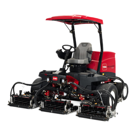
Toro Reelmaster 5510 Series Operator's Manual
8 or 11-blade dpa cutting unit with 7in reel
Hide thumbs
Also See for Reelmaster 5510 Series:
- Operator's manual (20 pages) ,
- Service manual (662 pages)
Table of Contents
Advertisement
Quick Links
Register at www.Toro.com.
Original Instructions (EN)
8- or 11-Blade DPA Cutting Unit
with 7in Reel
Reelmaster
®
5510/5610 Series Traction Unit
Model No. 03693—Serial No. 315000001 and Up
Model No. 03696—Serial No. 315000001 and Up
Model No. 03697—Serial No. 315000001 and Up
Form No. 3391-981 Rev B
*3391-981* B
Advertisement
Table of Contents

Related Manuals for Toro Reelmaster 5510 Series


Summary of Contents for Toro Reelmaster 5510 Series
- Page 1 8- or 11-Blade DPA Cutting Unit with 7in Reel Reelmaster ® 5510/5610 Series Traction Unit Model No. 03693—Serial No. 315000001 and Up Model No. 03696—Serial No. 315000001 and Up Model No. 03697—Serial No. 315000001 and Up *3391-981* B Register at www.Toro.com. Original Instructions (EN)
- Page 2 2), which signals a hazard that may cause additional information, contact an Authorized Service serious injury or death if you do not follow the Dealer or Toro Customer Service and have the model recommended precautions. and serial numbers of your product ready.
-
Page 3: Table Of Contents
Remove the key from the ignition switch to prevent the engine from accidently starting when servicing, adjusting, or storing the machine. • Perform only those maintenance instructions described in this manual. For major repairs or assistance, contact an authorized Toro distributor. -
Page 4: Safety And Instructional Decals
Safety and Instructional Decals Safety decals and instructions are easily visible to the operator and are located near any area of potential danger. Replace any decal that is damaged or missing. The roller Rebuild Kit, Part No. 114–5430 decal93-6688 93-6688 1. -
Page 5: Setup
Setup Loose Parts Use the chart below to verify that all parts have been shipped. Procedure Description Qty. Cutting unit Inspect the cutting unit. Use the kickstand when tipping the – No parts required cutting unit. – No parts required Adjust the rear shield. -
Page 6: Adjusting The Rear Shield
g003318 g003316 Figure 3 Figure 4 1. Cutting unit kickstand 1. Rear shield 2. Cap screw Adjusting the Rear Shield Mounting the Counter Weights No Parts Required No Parts Required Procedure Procedure Under most conditions, the cutting unit produces best dispersion when you close the rear shield (front All cutting units are shipped with the counter weight discharge). -
Page 7: Product Overview
69 kg (151 lb) Cutting Unit Accessories and Kits To ensure optimum performance and continued safety certification of the machine, use only genuine Toro replacement parts and accessories. Replacement parts and accessories made by other manufacturers could be dangerous, and such use could void the product warranty. -
Page 8: Operation
You will need the following tools to complete this with the roller rebuild kit procedure: • Shim 0.05 mm (0.002 inch)—Toro Part No. 125-5611 • Cutting performance paper—Toro Part No. 125-5610 Position the cutting unit on a flat, level work surface. - Page 9 Each click turned moves the bedknife 0.022 mm (0.0009 inch). Do not overtighten the adjusting screws. Test the cutting performance by inserting a long strip of cutting performance paper (Toro Part No. 125-5610) between reel and bedknife, g020158 Figure 9...
- Page 10 Adjusting the Rear Roller Adjust the rear roller brackets (Figure 11) to the desired height-of-cut range by positioning the required amount of spacers below the side plate mounting flange (Figure 11) per the height-of-cut chart; refer to Height-of-Cut Chart (page 12).
-
Page 11: Turf Compensation Settings
Turf Compensation Note: When operating the machine on rough terrain, decrease the spring length by 12.7 mm Settings (1/2 inch). Note: Adjust the turf compensation setting if The turf compensation spring transfers the weight the HOC setting or the aggressiveness of cut from the front to the rear roller. - Page 12 Aggressiveness of Cut Cutting unit aggressiveness of cut has a significant impact on the performance of the cutting unit. Aggressiveness of Cut refers to the angle of the bedknife relative to the ground (Figure 17). The best cutting unit setup depends on your turf conditions and desired results.
- Page 13 Height-of-Cut Adjustment Chart (cont'd.) HOC Setting Aggressiveness of Cut No. of Rear Spacers No. of Chain Links With Groomer kits installed Less 2.86 cm (1-1/4 inches) Normal More Less 3.18 cm (1-1/4 Normal inches)* + More Less 3.49 cm (1-3/8 inches)*+ Normal More Less...
- Page 14 Adjusting the Height of Cut Hook the screw head on the cutting edge of the bedknife and rest the rear end of the bar on the Note: For heights of cut greater than 2.54 cm (1 rear roller (Figure 20). inch), install the High Height-of-Cut Kit.
- Page 15 Figure 21 cutting unit to achieve the sharp edges needed 1. Bedknife lip height* for precision cutting (Refer to the Toro Manual for Sharpening Reel and Rotary Mowers, Form No. 09168SL). Checking and Adjusting the...
-
Page 16: Servicing The Bedknife
Note: Do not make the lead-in chamfer too large as it may cause turf tufting. g006504 Figure 22 1. Lead-in chamfer on right end of bedknife Servicing the Bedknife Bedknife Chart The bedknife service limits and grind angles are listed in the following chart. Important: Operating the cutting unit with the bedknife below the service limit may result in poor after-cut appearance and reduce the structural integrity of the bedknife for impacts. - Page 17 Recommended Top and Front Bedknife Grind Angles Refer to Figure 23 and the dimensions and angles listed in the Bedknife Chart (page 16). g025579 Figure 23 1. Bedknife Service Limit* 3. Front grind angle 2. Top grind angle Measuring the Bedknife Service Limit Note: All bedknife service limit measurements reference the bottom of the bedknife, refer to the Figure 24...
-
Page 18: Maintenance
Maintenance Lubricating the Cutting Unit Each cutting unit has 6 grease fittings (Figure 25) that must be lubricated regularly with No. 2 lithium grease. g020697 Figure 27 If end play exists, proceeded as follows: Loosen external set screw securing bearing adjusting nut to bearing housing located on the left side of the cutting unit (Figure... -
Page 19: Servicing The Bedbar
Servicing the Bedbar Removing the Bedbar Turn bedbar adjuster screws counterclockwise to back the bedknife away from the reel (Figure 29). g003335 Figure 31 1. Bedbar bolt 3. Steel washer 2. Nut 4. Nylon washer g006498 Figure 29 1. Bedbar adjusting screw 3. -
Page 20: Servicing The Hd Dual Point Adjusters (Dpa)
Servicing the HD Dual Point Install a wave washer onto the adjuster shaft and slide the adjuster shaft into the flange bushings Adjusters (DPA) in the cutting unit frame (Figure 33). Secure the adjuster shaft with a flat washer and Remove all parts (refer to Installation Instructions locknut (Figure... -
Page 21: Servicing The Roller
The Roller Rebuild Tool Kit includes all the tools and the installation instructions required to rebuild a roller with the roller rebuild kit. Refer to your Parts Catalog or contact your Authorized Toro Distributor for assistance. g007790 Figure 34 1. - Page 22 The method of transmission shall be electronic transmittal. This machinery shall not be put into service until incorporated into approved Toro models as indicated on the associated Declaration of Conformity and in accordance with all instructions, whereby it can be declared in conformity with all relevant Directives.
- Page 23 The Way Toro Uses Information Toro may use your personal information to process warranty claims, to contact you in the event of a product recall and for any other purpose which we tell you about. Toro may share your information with Toro's affiliates, dealers or other business partners in connection with any of these activities. We will not sell your personal information to any other company.
- Page 24 Countries Other than the United States or Canada Customers who have purchased Toro products exported from the United States or Canada should contact their Toro Distributor (Dealer) to obtain guarantee policies for your country, province, or state. If for any reason you are dissatisfied with your Distributor's service or have difficulty obtaining guarantee information, contact the Toro importer.
Need help?
Do you have a question about the Reelmaster 5510 Series and is the answer not in the manual?
Questions and answers