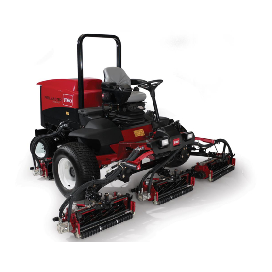
Toro Reelmaster 5410-D Operator's Manual
Traction unit
Hide thumbs
Also See for Reelmaster 5410-D:
- Operator's manual (72 pages) ,
- Service manual (662 pages) ,
- Operator's manual (128 pages)

Subscribe to Our Youtube Channel
Related Manuals for Toro Reelmaster 5410-D


Summary of Contents for Toro Reelmaster 5410-D
- Page 1 Form No. 3455-813 Rev A Reelmaster ® 5410-D and 5510-D Traction Unit Model No. 03952—Serial No. 400000000 and Up Model No. 03954—Serial No. 400000000 and Up *3455-813* Register at www.Toro.com. Original Instructions (EN)
- Page 2 It is a violation of California Public Resource Code additional information, contact an Authorized Service Section 4442 or 4443 to use or operate the engine on Dealer or Toro Customer Service and have the model and serial numbers of your product ready. Figure 1...
-
Page 3: Table Of Contents
Replacing a 12 V Fuse-Block Fuse ....75 Understanding the Warm-Up Mode....37 Replacing the TEC Fuse........75 Understanding Toro Smart Power™ ....37 Replacing the ECU Fuse ........76 Starting the Engine ........... 38 Drive System Maintenance ........77 Shutting Off the Engine........ -
Page 4: Safety
Safety Hydraulic System Safety........81 Hydraulic Fluid Specifications......81 Checking the Hydraulic-Fluid Level....82 This machine has been designed in accordance Checking the Hydraulic Lines and with EN ISO 5395 (when you complete the setup Hoses............82 procedures) and ANSI B71.4-2017. Hydraulic Fluid Capacity ........ -
Page 5: Safety And Instructional Decals
Safety and Instructional Decals Safety decals and instructions are easily visible to the operator and are located near any area of potential danger. Replace any decal that is damaged or missing. decal106-6754 decalbatterysymbols 106-6754 Battery Symbols 1. Warning—do not touch the hot surface. Some or all of these symbols are on your battery 2. - Page 6 decal120-4158 120-4158 1. Read the Operator’s 3. Engine—preheat Manual. 2. Engine—start 4. Engine—stop decal136-2159 136-2159 1. Move seat down 3. Rotate seat 2. Slide seat forward decal133-8062 133-8062 decal137-8127 137-8127 1. Attention—do not spray with high-pressure water. decal145-2519 145-2519 decal136-3702 1.
- Page 7 decal145-2483 145-2483 1. Parking brake 5. PTO—Disengage 2. Cruise control 6. PTO—Engage 3. Lower the cutting units. 7. Read the Operator’s Manual. 4. Raise the cutting units.
- Page 8 decal133-2930 133-2930 1. Warning—do not operate this machine unless you are trained. 4. Tipping hazard—drive slowly when turning; do not turn sharply while traveling fast; only drive on slopes with the cutting units lowered; always wear a seatbelt. 2. Warning—wear hearing protection. 5.
- Page 9 decal145-2573 145-2573 1. Check every 8 hours. 8. Battery 15. Fuel/Water separator 2. Brake functions 9. Radiator screen 16. Fluids 3. Hydraulic fluid 10. Engine oil 17. Capacity 4. Tire pressure 11. Engine oil level 18. Fluid interval (hours) 5. Engine air filter 12.
-
Page 10: Setup
Setup Loose Parts Use the chart below to verify that all parts have been shipped. Procedure Description Qty. – No parts required Prepare the machine. – No parts required Adjust the control-arm position. Right front hose guide Install the cutting units. Left front hose guide Cutting-unit kickstand Install the cutting-unit kickstand. -
Page 11: Preparing The Machine
Preparing the Machine No Parts Required Procedure Park the machine on a level surface, lower the cutting units, and engage the parking brake. Shut off the engine, remove the key, and wait for all moving parts to stop. Check the tire air pressure before use; refer to Checking the Tire Air Pressure (page 77). - Page 12 Positioning the Turf Compensating Spring and Installing the Hose Guide Cutting Units 4 g003975 Figure 4 1. Snapper pin 2. Cap g375671 Figure 6 1. Cutting unit 1 5. Cutting unit 5 Preparing the Cutting Units 2. Cutting unit 2 6.
- Page 13 g375690 Figure 8 g375694 Figure 10 1. Carriage bolt (3/8 x 1-1/4 3. Flange locknut (3/8 inch) 1. Flange locknut (3/8 inch) 3. Capscrew inches) 2. Right tab (Carrier frame) 2. Turf-compensator bracket Align the studs of the left hose guide with Remove the flange locknut (3/8 inch) that the holes in the cutting-unit frame and the secures the capscrew of the turf compensation...
- Page 14 Installing the Hose Guide Cutting Units 5 g375672 g375690 Figure 12 Figure 14 1. Cutting unit 1 5. Cutting unit 5 1. Carriage bolt (3/8 x 1-1/4 3. Flange locknut (3/8 inch) 6. Reel motor 2. Cutting unit 2 inches) 7.
- Page 15 Positioning the Turf Compensating Spring Cutting Unit 2 g379514 g375690 Figure 16 Figure 18 1. Cutting unit 1 5. Cutting unit 5 1. Carriage bolt (3/8 x 1-1/4 3. Flange locknut (3/8 inch) 6. Reel motor 2. Cutting unit 2 inches) 7.
- Page 16 g375694 Figure 20 1. Flange locknut (3/8 inch) 3. Capscrew 2. Right tab (Carrier frame) g004144 Align the holes in the turf-compensator bracket Figure 22 with the holes in the cutting-unit frame (Figure 21). 1. Chain bracket 3. Cutting-unit kickstand 2.
- Page 17 Lock the cutting-unit pivot for cutting grass on a hill side; refer to Locking the Cutting-Unit Pivot for Cutting Grass on a Hill Side (page 18). Installing the Rear Cutting Units to the Lift Arms Cutting Units adjusted for a 1.2 cm (3/4 inch) or Higher Height of Cut g375236 Figure 25...
- Page 18 g375239 g003948 Figure 27 Figure 29 1. Lynch pin 3. Lift arm 1. Lift-arm chain 3. Snapper pin 2. Lift-arm shaft 4. Washer 2. Chain bracket Insert the pivot yoke into the lift arm, and secure shaft to the arm with the lynch pin and washer. Installing the Reel Motors Repeat steps through...
-
Page 19: Using The Cutting-Unit Kickstand
Using the Cutting-Unit Kickstand Parts needed for this procedure: Cutting-unit kickstand Procedure Whenever you need to tip the cutting unit to expose the bedknife/reel, prop up the rear of the cutting unit with the kickstand to make sure that the nuts on the g004144 back end of the bedbar-adjusting screws are not Figure 32... -
Page 20: Applying The Ce Decals
Close the hood, and use the enclosed hood-latch key to check that the hook of the lock engages the frame catch when locked. Applying the CE Decals Parts needed for this procedure: CE decal Production year decal Warning decal g027072 Figure 33 1. -
Page 21: Product Overview
Product Overview g375339 Figure 36 1. Year of production decal 2. Serial plate Remove the backing from the year of production decal. Apply the decal to the floor bracket. g216864 Figure 38 1. Engine hood 5. Seat adjustments Applying the CE Warning Decal 2. - Page 22 Key Switch The key switch (Figure 39) has 3 positions: O , and S REHEAT TART Power-takeoff (PTO) Switch When the PTO switch is engaged, the machine is in mode, which allows you to drive up to 13 km/h (8 mph) when the maximum speed is not limited. g383839 When the PTO switch is not engaged (Figure...
-
Page 23: Seat Controls
units. When you lower the cutting units before the PTO switch is engaged, they do not start spinning. To fully raise the cutting units, pull the lever backward. When the cutting units are raised and the PTO switch is disengaged, the machine is in T mode. - Page 24 g021209 Figure 45 1. Backlap levers...
-
Page 25: Specifications
To ensure optimum performance and continued safety Before Operation Safety certification of the machine, use only genuine Toro replacement parts and accessories. Replacement parts and accessories made by other manufacturers General Safety could be dangerous, and such use could void the •... -
Page 26: Performing Daily Maintenance
• • Before mowing, always inspect the machine to Never mix kerosene or used engine oil with the ensure that the cutting units are in good working diesel fuel. condition. • Never keep fuel in containers with zinc plating on •... -
Page 27: Checking The Interlock Switches
Fuel filter plugging may be expected for a time after converting to biodiesel blends. Preparing the Machine • Contact your authorized Toro distributor for more Drive the machine slowly to an open area. information on biodiesel. Lower the cutting units, shut off the engine, and engage the parking brake. -
Page 28: Using The Infocenter Lcd Display
Note: There should be no machine response when you press the traction pedal while the parking brake is engaged. An advisory message should appear on the InfoCenter. Checking the Automatic Parking Brake Engage Sit in the operator’s seat. Start the engine. Disengage the parking brake. -
Page 29: Using The Menus
Start the engine. High exhaust temperature Shut off the engine. NOx control diagnosis malfunction; Engine drive the machine back to the shop and contact your authorized Toro Key switch distributor (software version U and later). DPF ash-accumulation The cutting units are lowering. - Page 30 Indicates the inputs, qualifiers machine faults. Refer to the and outputs for starting the Service Manual or contact your engine. authorized Toro distributor for more information on the Faults Backlap Indicates the inputs, qualifiers menu and the information and outputs for operating the contained there.
-
Page 31: Protected Menus
If you changed the PIN code and forgot the code, Note: If the InfoCenter accepts the PIN code contact your authorized Toro distributor for assistance. and the protected menu is unlocked, the word “PIN” displays in the upper right corner of the... - Page 32 Settings to O , set the PIN code, and turn the HOC into the InfoCenter, the setting can be manually key in the ignition switch to the O position and changed to accommodate for different mowing then to the O position.
-
Page 33: Checking The Hydrostatic Braking Distance
For smooth deceleration, use your foot to slowly control the traction pedal back to neutral. Do • Contact your authorized Toro distributor if the not take your foot off the pedal and allow it to snap machine's observed speeds deviate more than 2.4 back to the neutral position unless you intend to stop km/h (1.5 mph) from the displayed speeds. - Page 34 Rollover Protection System hair and do not wear loose clothing or loose jewelry. (ROPS) Safety • Do not operate the machine while ill, tired, or • Do not remove any of the ROPS components from under the influence of alcohol or drugs. the machine.
-
Page 35: Understanding The Operating Characteristics Of The Machine
Practice Operating the Machine caves in. Establish a safety area between the machine and any hazard. • To get familiar with the features of the machine, – Identify hazards at the base of the slope. practice operating the machine. If there are hazards, mow the slope with a •... -
Page 36: Using The Virtual Pedal Stop (Vps) Feature
the traction pedal is automatically reprogrammed to use the full pedal stroke between neutral and the new max speed. This means the operator gains more precise control of the traction speed at lower maximum speed settings. Tips for Using Virtual Pedal Stop (VPS) •... -
Page 37: Understanding The Acceleration Mode
• On rough terrain, use the InfoCenter to control the speed. Understanding Toro Smart • Use the cruise control for turnarounds as follows: Power™ While mowing, set a safe, comfortable speed... -
Page 38: Starting The Engine
controlling the machine speed and optimizing cutting Tap the lift/lower control lever rearward to lift the performance. cutting units to the turnaround position. Note: By default, the Smart Power feature is O Note: Tapping the lift/lower control lever without holding it raises the cutting units to the turnaround position and stops the rotation of the Starting the Engine reels until the cutting units are lowered. - Page 39 • Passive regeneration occurs continuously while speed to help reduce the accumulation of soot in the engine is running—run the engine at full the soot filter. engine speed when possible to promote DPF regeneration. DPF Soot Accumulation • If the back pressure in the DPF is too high or a •...
- Page 40 DPF Ash Accumulation • When enough ash accumulates, the engine computer sends information to the InfoCenter • The lighter ash is discharged through the exhaust in the form of an engine fault to indicate the system; the heavier ash collects in the soot filter. accumulation of ash in the DPF.
- Page 41 Types of Diesel Particulate Filter Regeneration Types of diesel particulate filter regeneration that are performed while the machine is operating: Type of Regeneration Conditions that cause DPF regeneration DPF description of operation Passive Occurs during normal operation of the machine at •...
- Page 42 Types of diesel particulate filter regeneration that require you to park the machine: (cont'd.) Type of Regeneration Conditions that cause DPF regeneration DPF description of operation Recovery Occurs because the operator ignored requests for • When the reset-standby/parked or recovery a parked regeneration and continued operating the machine, adding more soot to the DPF regeneration icon...
- Page 43 press the right button to select the Technician entry DPF Operation Table (cont'd.) (Figure 61). State Description Reset Regen The engine computer is running a reset regeneration. The engine computer is requesting that Parked Stby you run a parked regeneration. Parked Regen You initiated a parked regeneration request and the engine computer is...
- Page 44 Assist DPF Regeneration • The icon displays in the InfoCenter while the reset regeneration is processing. • The engine computer adjusts engine settings to • Whenever possible, do not shut off the engine or raise the exhaust temperature. reduce engine speed while the reset regeneration •...
- Page 45 g227304 g224394 Figure 66 Figure 68 Press the right button to change the inhibit Note: If the engine exhaust temperature is too low, regeneration setting from On to Off (Figure the InfoCenter displays A #186 (Figure 69) to DVISORY or from Off to On (Figure 67).
- Page 46 Parked or Recovery Regeneration regeneration required—power takeoff disabled #189 (Figure 73). DVISORY • When the engine computer requests either a parked regeneration or a recovery regeneration, the regeneration request icon (Figure 70) displays in the InfoCenter. g224398 Figure 73 Important: Perform a parked regeneration to restore the PTO function;...
- Page 47 Important: Perform a recovery regeneration Move the machine outside to an area away from to restore the PTO function; refer to Preparing combustible materials. to Perform a Parked or Recovery Regeneration Park the machine on a level surface. (page 47) Performing a Parked or Recovery Regeneration (page 47).
- Page 48 At the DPF checklist screen, verify that the parking brake is engaged and that the engine speed is set to low idle (Figure 81). g224402 g224407 g224629 Figure 79 At the V screen, verify that you g227679 ERIFY FUEL LEVEL Figure 81 have 1/4 tank of fuel if you are performing the parked regeneration or 1/2 tank of fuel if you are...
- Page 49 The InfoCenter displays the I NITIATING Check Message and Corrective Action Table message (Figure 83). EGEN (cont'd.) g224411 Corrective Action: Start and run the engine. g227681 Figure 83 Corrective Action: Run the engine to warm the coolant The InfoCenter displays the time to complete temperature to 60°C (140°F).
- Page 50 Canceling a Parked or Recovery Regeneration displays A #183 (Figure 86). Press the DVISORY left button to exit to the home screen. Use the Parked Regen Cancel or Recovery Regen Cancel setting to cancel a running parked or recovery regeneration process. Access the DPF Regeneration menu (Figure 88).
-
Page 51: Adjusting The Turf-Compensation Spring
Adjusting the for different turf conditions, and to maintain a uniform height of cut in rough conditions or in areas of thatch Turf-Compensation Spring buildup. You can adjust counterbalance force of each torsion The turf-compensation spring transfers weight from spring to 1 of 4 settings. Each increment increases or the front to the rear roller (Figure 90). -
Page 52: Adjusting The Lift-Arm Turnaround Position
Adjusting the Lift-Arm Important: Do not overtighten the jam nuts; otherwise, you may damage the sensor. Turnaround Position Park the machine on a level surface, lower the cutting units, shut off the engine, engage the parking brake, and remove the key. The lift-arm switch is located underneath the hydraulic tank and inboard of the cutting unit #5 lift arm... -
Page 53: Setting The Reel Speed
Setting the Reel Speed Important: It is important that proper reel speeds are used for your mowing application. Reel speeds that are too slow may result in a wave pattern in the turf, also known as clip marks, marcelling, or bobbing. If this is observed, try increasing the reel speeds or reducing the mowing speed. Reel speeds that are too fast may result in turf damage and/or premature wear of the reels, bedknives, and other mechanical components. -
Page 54: Understanding The Diagnostic Light
g420088 Figure 95 7 inch (178 mm) Reel Speed Chart Understanding the Operating Tips Diagnostic Light Understanding the Warning The machine is equipped with a diagnostic light, which System indicates if the machine detects a malfunction. The diagnostic light is located on the InfoCenter, above If a warning light comes on during operation, stop the the display screen (Figure... -
Page 55: After Operation
a tree or other object in the distance and drive optimizing productivity by preventing the straight toward it. components from overheating. • Maintain reel and bedknife sharpness. – If the engine, generator, or reel motors overheat, park the machine in a shaded area •... -
Page 56: Hauling The Machine
Pushing or Towing the Machine In an emergency, you can move the machine forward by actuating the bypass valve in the variable-displacement hydraulic pump and pushing or towing the machine. Important: Do not push or tow the machine faster than 3 to 4.8 km/h (2 to 3 mph). If you push or tow at a faster speed, internal transmission damage may occur. - Page 57 g420086 Figure 100 1. Pump mechanism on the 2. Black knob brake manifold Insert the long end of a ratchet or similar object, hold the black knob in on the manifold, and pump the manifold 3 times. As soon as there is substantial resistance when pumping the brake is released.
-
Page 58: Maintenance
• To ensure safe, optimal performance of the slip-resistant footwear. Keep hands, feet, clothing, machine, use only genuine Toro replacement jewelry, and long hair away from moving parts. parts. Replacement parts made by other •... - Page 59 Maintenance Service Maintenance Procedure Interval • Inspect the cooling-system hoses. Every 100 hours • Check the alternator-belt tension. • Change the engine oil and filter. Every 250 hours • Torque the wheel lug nuts to 94 to 122 N∙m (70 to 90 ft-lb). •...
-
Page 60: Daily Maintenance Checklist
Daily Maintenance Checklist Duplicate this page for routine use. For the week of: Maintenance Check Item Mon. Tues. Wed. Thurs. Fri. Sat. Sun. Check the safety-interlock operation. Check the brake operation. Check the engine oil and fuel level. Drain the water/fuel separator. Check the air-filter-restriction indicator. -
Page 61: Pre-Maintenance Procedures
Pre-Maintenance Closing the Hood Procedures Carefully rotate the hood closed (Figure 102). Preparing for Maintenance Park the machine on a level surface, disengage the PTO, lower the cutting units, and engage the parking brake. Shut off the engine, remove the key, and wait for all moving parts to stop. -
Page 62: Closing The Screen
Closing the Screen Jacking Point Locations Close and latch the screen (Figure 104). Note: Support the machine with jack stands whenever you work under the machine. Use the following as machine-lift points: g378174 Figure 104 1. Ball pin 2. Screen latch Insert the ball pin through the screen latch. -
Page 63: Lubrication
Lubrication Greasing the Bearings and Bushings Service Interval: Every 50 hours (and immediately after every washing). Lubricate all grease fittings for the bearings and bushings with No. 2 lithium grease. The grease fitting locations and quantities are as follows: g003960 Figure 109 •... -
Page 64: Engine Maintenance
Engine Maintenance Engine Safety • Shut off the engine before checking the oil or adding oil to the crankcase. • Do not change the governor speed or overspeed the engine. Checking the Air Filter g003966 Figure 112 Service Interval: Before each use or daily Prepare the machine for maintenance;... -
Page 65: Servicing The Air Cleaner
If a red band displays in the service indicator, change the air filter; refer to Servicing the Air Cleaner (page 65). Squeeze the dust-ejector valve (Figure 114). g034923 g373568 Figure 114 Close and latch the hood; refer to Closing the Hood (page 61). -
Page 66: Resetting The Air Filter Service Indicator
Preferred oil: SAE 15W-40 (above -18°C (0°F)) • Alternate oil: SAE 10W-30 or 5W-30 (all temperatures) Toro Premium Engine Oil is available from your authorized Toro distributor in either 15W-40 or 10W-30 viscosity grades. Checking the Level of the Engine... - Page 67 Crankcase Oil Capacity Open the hood; refer to Opening the Hood (page 61). 5.2 L (5.5 US qt) with the filter Add oil to the crankcase; refer to Oil Specification (page 66), Crankcase Oil Capacity (page 67), Changing the Engine Oil and Filter Checking the Level of the Engine Oil (page 66).
-
Page 68: Fuel System Maintenance
Fuel System provider to correct the problem and perform all fuel system maintenance. Maintenance • Do not store diesel fuel in tanks or canisters made with zinc-plated components. Fuel Maintenance Servicing the Fuel-Water This Operator’s Manual contains more detailed Separator fuel and fuel system maintenance information than the Yanmar ®... -
Page 69: Servicing The Fuel Filter
g378468 Figure 121 1. Fuel-filter head 2. Fuel filter Remove the filter and clean the filter-head mounting surface (Figure 121). Note: Use a clean cloth to clean the filter head. Lubricate the filter gasket with clean lubricating engine oil; refer to the engine owner's manual for additional information. -
Page 70: Inspecting The Fuel Lines And Connections
Inspecting the Fuel Lines Contact your authorized Toro distributor to reset the engine ECU after you install a clean DPF. and Connections Cleaning the Fuel-Pickup Service Interval: Every 400 hours/Yearly (whichever comes first) Tube Screen Inspect the fuel lines for deterioration, damage, or loose connections. - Page 71 g373884 Figure 124 1. 2-pin connector (machine 2. 2-socket connector (fuel wire harness) sender) g373883 Figure 126 Move the clamps that secure the hoses to the fittings of the fuel sender inboard, and remove 1. Cap (fuel sender) the hoses from the fittings (Figure 125).
- Page 72 Cleaning the Installing the Fuel-Pickup Tube Clean the screen at the end of the fuel pick-up tube (Figure 127). g373882 Figure 129 1. Hoses 3. Fitting (fuel sender) 2. Clamp Plug the connector of the fuel-sender harness into the connector of the machine wire harness (Figure 130).
-
Page 73: Priming The Fuel System
Electrical System Maintenance Electrical System Safety • Disconnect the battery before repairing the machine. Disconnect the negative terminal first and the positive last. Connect the positive terminal first and the negative last. • Charge the battery in an open, well-ventilated area, away from sparks and flames. -
Page 74: Connecting The 12 V Battery
Apply a coat of Grafo 112X (skin-over) grease, Toro Part No. 505-47 to the battery posts and battery-cable clamps. Slide the rubber boot over the positive battery-cable clamp. Assemble the cover over the battery, inserting the tabs of the cover into the slots in the battery tray. -
Page 75: Replacing A 12 V Fuse-Block Fuse
Replacing a 12 V Fuse-Block Fuse The fuse block is under the seat. Prepare the machine for maintenance; refer to Preparing for Maintenance (page 61). Unlatch the seat base, tilt the seat base open, and support it with the prop rods (Figure 134). -
Page 76: Replacing The Ecu Fuse
g422078 g422077 Figure 137 Figure 138 1. TEC fuse 1. ECU fuse Replace the open fuse with a fuse of the same Replace the open fuse with a fuse of the same type and amperage rating. type and amperage rating. Assemble the cap to the in-line fuse holder. -
Page 77: Drive System Maintenance
Drive System Note: The rear wheel toe-in adjustment is correct if the difference between the front wheel Maintenance measurement and the rear wheel measurement is 6 mm (1/4 inch) or less. (Figure 139). Checking the Tire Air Pressure Service Interval: Before each use or daily Important: Maintain the recommended pressure in all tires to ensure a good quality of cut and... -
Page 78: Cooling System Maintenance
Cooling System At axle height, measure the center-to-center distance at the front and rear of the steering Maintenance tires. Note: The rear wheel toe-in adjustment is correct if the difference between the front wheel Cooling System Safety measurement and the rear wheel measurement is 6 mm (1/4 inch) or less. -
Page 79: Checking The Coolant Level
• Preferred option: If distilled water is not available, use a pre-mix coolant instead of a concentrate. • Minimum requirement: If distilled water and pre-mix coolant are not available, mix concentrated coolant with clean drinkable water. Checking the Coolant Level CAUTION If the engine has been running, the pressurized, hot coolant can escape and... - Page 80 Park the machine on a level surface, lower the Close the screen and secure the latch. cutting units, shut off the engine, engage the parking brake, and remove the key. Thoroughly clean all debris out of the engine area. Unlatch the clamp and pivot open the rear screen (Figure 142).
-
Page 81: Belt Maintenance
Check the deflection of the belt again to ensure that the tension is correct. Alternative hydraulic fluids: If Toro PX Extended Life Hydraulic Fluid is not available, you may use another conventional, petroleum-based hydraulic fluid having specifications that fall within the listed range for all the following material properties and that it meets industry standards. -
Page 82: Checking The Hydraulic-Fluid Level
Remove the cap/dipstick from the filler neck and This fluid is compatible with the elastomers used wipe it with a clean rag. in Toro hydraulic systems and is suitable for a Insert the dipstick into the filler neck; then wide-range of temperature conditions. This fluid is remove it and check the level of fluid. -
Page 83: Replacing The Hydraulic Filters
Hydraulic-Fluid Level (page 82) filled the reservoir with an alternative fluid, change the hydraulic fluid. Replacing the Hydraulic If the fluid becomes contaminated, contact your Toro Filters Distributor because the system must be flushed. Contaminated fluid looks milky or black when compared to clean fluid. - Page 84 g422076 Figure 149 1. Filter head 2. Charge filter g376340 Figure 148 1. Return filter 2. Filter head Remove the filter. Wipe clean the filter mounting area of the filter Remove the filter. head. Wipe clean the filter mounting area of the filter Apply a thin coat of the specified hydraulic fluid head.
-
Page 85: Cutting Unit Maintenance
DANGER Note: Additional instructions and procedures on Changing the engine speed while backlapping backlapping are available in the Toro Reel Mower may cause the reels to stall. Basics (with sharpening guidelines), Form 09168SL. • Never change the engine speed while backlapping. - Page 86 forward to start the backlapping operation on the designated reels. Apply lapping compound with a long-handled brush. DANGER Contacting the cutting units when they are moving could cause personal injury. g377117 To avoid personal injury, be certain that Figure 151 you are clear of the cutting units before 1.
-
Page 87: Chassis Maintenance
Extended Maintenance Chassis Maintenance Inspecting the Seat Belt Chassis and Engine Service Interval: Before each use or daily Service Interval: Every 2 years—Replace the hydraulic hoses. Inspect the seat belt for wear, cuts, and other damage. Replace the seat belt(s) if any Every 2 years—Replace the coolant hoses. -
Page 88: Cleaning
Clean the battery, terminals, and posts with a wire brush and baking-soda solution. Coat the cable terminals and battery posts with Grafo 112X skin-over grease (Toro Part No. 505-47) or petroleum jelly to prevent corrosion. Slowly charge the battery every 60 days for 24 hours to prevent lead sulfation of the battery. -
Page 89: Preparing The Engine
Preparing the Engine Drain the engine oil from the oil pan and install the drain plug. Remove and discard the oil filter. Install a new oil filter. Fill the engine with specified motor oil. Start the engine and run it at idle speed for approximately 2 minutes. - Page 90 The Toro Company (“Toro”) respects your privacy. When you purchase our products, we may collect certain personal information about you, either directly from you or through your local Toro company or dealer. Toro uses this information to fulfil contractual obligations - such as to register your warranty, process your warranty claim or to contact you in the event of a product recall - and for legitimate business purposes - such as to gauge customer satisfaction, improve our products or provide you with product information which may be of interest.
- Page 91 While the exposure from Toro products may be negligible or well within the “no significant risk” range, out of an abundance of caution, Toro has elected to provide the Prop 65 warnings. Moreover, if Toro does not provide these...
- Page 92 Countries Other than the United States or Canada Customers who have purchased Toro products exported from the United States or Canada should contact their Toro Distributor (Dealer) to obtain guarantee policies for your country, province, or state. If for any reason you are dissatisfied with your Distributor's service or have difficulty obtaining guarantee information, contact your Authorized Toro Service Center.
Need help?
Do you have a question about the Reelmaster 5410-D and is the answer not in the manual?
Questions and answers