Table of Contents
Advertisement
Available languages
Available languages
Quick Links
For projecting
and non-projecting
up-and-over doors,
and sectional doors
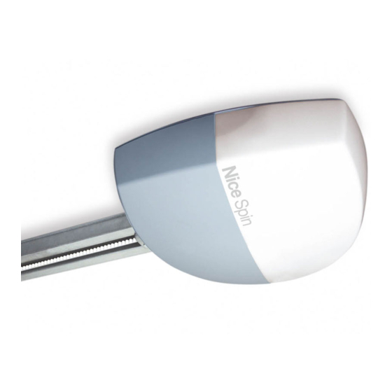
Spin
Instructions and warnings for the fitter
Istruzioni ed avvertenze per l'installatore
Instructions et recommandations pour l'installateur
Anweisungen und Hinweise für den Installateur
Instrucciones y advertencias para el instalador
Instrukcje i uwagi dla instalatora
Aanwijzingen en aanbevelingen voor de installateur
Advertisement
Chapters
Table of Contents

Related Manuals for Nice Spin Series


Summary of Contents for Nice Spin Series
- Page 1 For projecting and non-projecting up-and-over doors, and sectional doors Spin Instructions and warnings for the fitter Istruzioni ed avvertenze per l’installatore Instructions et recommandations pour l’installateur Anweisungen und Hinweise für den Installateur Instrucciones y advertencias para el instalador Instrukcje i uwagi dla instalatora Aanwijzingen en aanbevelingen voor de installateur...
-
Page 2: Table Of Contents
Spin Table of contents: page Warnings Maintenance and Disposal Maintenance Product description Disposal Operating limits Typical system Additional information List of cables Programming buttons Programming Installation 7.2.1 Level one functions (ON-OFF functions). Preliminary checks 7.2.2 Level one programming (ON-OFF functions). Fitting SPIN 7.2.3 Level two functions (adjustable parameters) -
Page 3: Warnings
If necessary, According to the most recent European legislation, the please contact the NICE customer service department; the use of production of automatic doors or gates is governed by the SPIN in these conditions can be dangerous. -
Page 4: Operating Limits
2.1) Operating limits Chapter 8 “Technical Characteristics” provides the data needed to determine whether the products of the SPIN line are suitable for the intend- ed application. The structural characteristics of the SPIN products make it suitable for use on sectional and overhead doors within the limits shown in Tables 3, 4 and 5. -
Page 5: List Of Cables
2.2) Typical system Figure 2 shows a typical system for automating a sectional door. SPIN Main edge Key-operated selector switch Photocells Flashing light with incorporated PP function cord Photocells on post (fig. 3) aerial Radio-transmitter Figures 3 and 4 show typical installations of a protruding and non-protruding overhead door For installations on overhead doors, the accessory SPA5 is required. -
Page 6: Installation
3) Installation The installation of SPIN must be carried out by qualified 2970mm 380mm personnel in compliance with current legislation, standards and regulations, and the directions provided in this manual. 3.1) Preliminary checks 0÷400mm Before proceeding with the installation of SPIN you must: •... -
Page 7: Typical System 5
3.2.1) Assembly of guide supplied with SPIN20KCE, SPIN30 and SPIN40 The guide supplied with SPIN20KCE, SPIN30 and SPIN40 must be assembled as follows: 1. Lay the three guide parts to enable them to be joined. Pay attention to the position of the belt; this must have the teeth facing inwards, and be straight without any twists. -
Page 8: Fixing The Gearmotor To The Guide
5. Return the belt tensioner device and carriage to the initial position. Assemble the guide head section (A), as shown in figure 17. This requires a certain force; if necessary use a rubber mallet. 6. Insert the spring, washer and M8 nut (D), in the screw of the belt tensioner device, as shown in figure 18. 7. - Page 9 2. After drilling the holes in the relative points, leaving the gearmotor on the ground, lift the guide from the front section and secure by means of two screws, plugs or rivets, according to the installation surface. 3. Secure the brackets (I) by means of the M6x15 screws (G) and nuts M6 (H) selecting the hole most suited to ensure distance B, as shown in figure 25.
-
Page 10: Installation Of The Various Devices
3.3) Installation of the Various Devices If other devices are needed, install them following the directions provided in the corresponding instructions. Check this in paragraph “3.5 Description of electrical connections” and the devices which can be connected to the SPIN in Figure 2.. 3.4) Electrical connections Only carry out electrical connections once the electric- 2. -
Page 11: Description Of The Electrical Connections
FLASH: this output is programmable (see paragraph 7.2.4) for connection of one of the following devices: Flashing light If programmed as “flashing light” on the “FLASH” output a NICE “LUCY B” flashing light can be connected with a car type 12V 21W lamp. -
Page 12: Recognition Of The Devices
4.2) Recognition of the devices After connecting up the power supply, the control unit must be made to recognise the devices connected up to the BLUEBUS and STOP inputs. Before this phase, LEDs L1 and L2 will flash to indicate that recognition of the devices must be carried out. -
Page 13: Preset Functions
4.5) Preset functions The SPIN control unit has a number of programmable functions. These special programming procedure. Please refer to paragraph “7.2 Pro- functions are set to a configuration which should satisfy most automa- gramming” for further information about this. tions. -
Page 14: Memorization Mode I
4.6.2) Memorization mode I Table 11: to memorize a transmitter in mode I Example Press the key on the receiver and hold it down (approx. 3s) Release the key when the LED on the receiver lights up Within 10s, press any key on the radio transmitter to be memorized and hold it down for at least 2s If the memorization procedure is successful, the LED on the receiver will flash 3 times. -
Page 15: Deleting The Radio Transmitters
4.6.5) Deleting the Radio Transmitters Table 14: to delete all the radio transmitters Example Press the key on the receiver and hold it down Wait until the LED lights up, then wait until it goes off, then wait until it has flashed 3 times Release the key precisely upon the third flash. -
Page 16: Commissioning
5.2) Commissioning Commissioning can take place only after all testing phases have been 4. Post a label on the door providing at least the following data: terminated successfully. It is not permissible to execute partial com- type of automation, name and address of manufacturer (person missioning or to enable use of the system in makeshift conditions. -
Page 17: Additional Information
7) Additional Information Programming, personalisation and how to look for and deal with faults on the SPIN will be dealt with in this chapter. 7.1) Programming keys The SPIN control unit feature three keys that can be used to com- mand the control unit both during tests and programming: Open The “OPEN”... -
Page 18: Level One Programming (On-Off Functions)
7.2.2) Level one programming (ON-OFF functions) Level 1 functions are all factory set to “OFF”. However, they can be changed at any time as shown in Table 16. Follow the procedure care- fully, as there is a maximum time of 10 seconds between pressing one key and another. If a longer period of time lapses, the procedure will finish automatically and memorize the modifications made up to that stage. -
Page 19: Level One Programming Example (On-Off Functions)
7.2.5) Level one programming example (ON-OFF functions) The sequence to follow in order to change the factory settings of the functions for activating “Automatic Closing” (L1) and “Motor force” (L3) have been included as examples Table 19: Level one programming example Example Press the key [Set] and hold it down (approx. -
Page 20: Stop Input
7.3.2) STOP Input STOP is the input that causes the immediate interruption of the • Two devices with 8.2KΩ constant resistance output can be con- manoeuvre (with a short reverse run). Devices with output featuring nected in parallel; if needed, multiple devices must be connected normally open “NO”... -
Page 21: Recognition Of Other Devices
7.3.4) Recognition of other devices Normally the recognition of the devices connected to the BlueBUS and the STOP input takes place during the installation stage. However, if new devices are added or old ones removed, the recognition process can be gone through again by proceeding as follows: Table 22: Recognition of Other Devices Example Press keys [s] and [Set] and hold them down [Set] x 3s... -
Page 22: Troubleshooting
7.6) Troubleshooting The following table contains instructions to help you solve malfunc- tions or errors that may occur during the installation stage or in case of failure. Table 23: Troubleshooting SYMPTOMS PROBABLE CAUSE AND POSSIBLE SOLUTION The radio transmitter does not control the door Check to see if the transmitter batteries are exhausted, if necessary replace them. -
Page 23: Signals On The Control Unit
7.7.2) Signals on the control unit On the SPIN control unit there is a set of LED’s each of which can give special indications both during normal operation and in case of malfunctions. Table 25: LED’s on the control unit’s terminalsle BLUEBUS Led Cause ACTION... -
Page 24: Accessories
7.8) Accessories The following optional accessories are available for SPIN. For information on the complete range of accessories, refer to the Nice s.p.a. prod- uct catalogue. For SN6031 and SN6041 • PS124 24 V Buffer battery – 1.2Ah with integrated charger battery For SN6031 and SN6041 •... -
Page 25: Technical Characteristics
8) Technical characteristics Nice S.p.a., in order to improve its products, reserves the right to modify their technical characteristics at any time without prior notice. In any case, the manufacturer guarantees their functionality and fitness for the intended purposes. All the technical characteristics refer to a room temperature of 20°C (±5°C) - Page 26 Guide technical characteristics Model Guide in SPIN20KCE Guide in SPIN40 SNA5 SNA6 and SPIN30 Type single profile in 2-piece profile in 3-piece profile in galvanised steel galvanised steel galvanised steel Guide length 3.15m 3.15m 3.15m 4.15m Guide height 35mm 35mm 35mm 35mm Useful stroke...
-
Page 27: Instructions And Warnings For Users Of Spin Gearmotor
This operation • Children: automation systems are designed to has been carefully designed by Nice to make it guarantee high levels of safety and security. They extremely easy, without any need for tools or physi- are equipped with detection devices that prevent cal exertion. - Page 28 Are you satisfied? If you wish to install another automation system in your home, call your old installation technician and use Nice products. You will get the services of a specialist and the most advanced products available on the mar- ket, superior performances and maximum system compatibility.
- Page 30 Spin Indice: pag. Avvertenze Manutenzione e smaltimento Manutenzione Descrizione prodotto Smaltimento Limiti d’impiego Impianto tipico Approfondimenti Elenco cavi Tasti di programmazione Programmazioni Installazione 7.2.1 Funzioni primo livello (funzioni ON-OFF) Verifiche preliminari 7.2.2 Programmazione primo livello Fissaggio SPIN (funzioni ON-OFF) 3.2.1 Assemblaggio guida in dotazione a 7.2.3 Funzioni secondo livello...
-
Page 31: Avvertenze 31
• Durante l’installazione e l’uso evitare che parti solide o liquidi possano messa in servizio”. penetrare all’interno della centrale e di altri dispositivi aperti; eventual- mente rivolgersi al servizio di assistenza NICE; l’uso di SPIN in queste Secondo la più recente legislazione europea, la realizza- situazioni può causare situazioni di pericolo. -
Page 32: Limiti D'impiego
2.1) Limiti d’impiego I dati relativi alle prestazioni dei prodotti della linea SPIN sono riportati nel capitolo “8 Caratteristiche tecniche” e sono gli unici valori che con- sentono la corretta valutazione dell’idoneità all’uso. Le caratteristiche strutturali dei prodotti SPIN li rendono adatti all’uso su portoni di tipo sezionale o basculante, secondo i limiti riportati nelle tabelle N°3, 4 e 5. -
Page 33: Impianto Tipico
2.2) Impianto tipico Nella figura 2 è riportato l’installazione tipica per un portone di tipo sezionale. SPIN Bordo primario Selettore a chiave Fotocellule Lampeggiante con antenna Cordino funzione PP Fotocellule su colonnina (fig. 3) incorporata Trasmettitore radio Nelle figure 3, 4 sono riportate le installazioni tipiche per un portone basculante debordante e non debordante. Per installazioni su portoni basculanti è... -
Page 34: Installazione
3) Installazione L’installazione di SPIN deve essere effettuata da persona- 2970mm 380mm le qualificato, nel rispetto di leggi, norme e regolamenti e di quanto riportato nelle presenti istruzioni. 3.1) Verifiche preliminari 0÷400mm Prima di procedere con l’installazione di SPIN è necessario eseguire questi controlli: •... -
Page 35: Spin20Kce, Spin30 E Spin40
3.2.1) Assemblaggio guida in dotazione a SPIN20KCE, SPIN30 e SPIN40 La guida in dotazione a SPIN20KCE, SPIN30 e SPIN40 deve essere assemblata in questo modo: 1. Predisporre le tre parti che compongono la guida, in modo da poterle unire tra di loro. Fate attenzione alla posizione della cinghia: deve essere con i denti rivolti verso l’interno, dritta e senza attorcigliamenti. -
Page 36: Fissaggio Del Motoriduttore
5. Riportare nella posizione iniziale il rinvio tendi cinghia ed il carrello. Assemblare la testa della guida (A), come in figura 17. Questa opera- zione richiede una certa forza, eventualmente utilizzare un martello in gomma. 6. Inserire nella vite del rinvio tendi cinghia la molla, la rondella ed il dado M8 (D), come in figura 18. 7. - Page 37 2. Dopo avere forato nei punti previsti, lasciando il motoriduttore a terra, sollevare la guida dalla parte anteriore e fissarla con due viti, tasselli o rivetti a seconda della superficie. 3. Fissare le staffe (I) tramite le viti M6x15 (G) ed i dadi M6 (H) scegliendo il foro che consenta di rispettare il più possibile la quota B, come in figura 25.
-
Page 38: Installazione Dei Vari Dispositivi
3.3) Installazione dei vari dispositivi Effettuare l’installazione degli altri dispositivi previsti seguendo le rispettive istruzioni. Verificare nel paragrafo “3.5 Descrizione dei collegamenti elettrici” ed in figura 2 i dispositivi che possono essere collegati a SPIN. 3.4) Collegamenti elettrici Tutti i collegamenti elettrici devono essere eseguiti in 2. -
Page 39: Descrizione Dei Collegamenti Elettrici
FLASH: questa uscita è programmabile (vedere paragrafo 7.2.4) per collegare uno fra i seguenti dispositivi: Lampeggiante Se programmata come “lampeggiante” sull’uscita “FLASH” è possibile collegare un lampeggiante NICE “LUCY B” con una lampadina a 12V 21W tipo auto. Durante la manovra lampeggia con periodo 0.5s acceso e 0.5s spento. -
Page 40: Apprendimento Dei Dispositivi
4.2) Apprendimento dei dispositivi Dopo l’allacciamento dell’alimentazione occorre far riconoscere alla centrale i dispositivi collegati sugli ingressi BlueBUS e STOP. Prima di questa fase i led L1 ed L2 lampeggiano per indicare che occorre eseguire l’apprendimento dei dispositivi. La fase di apprendimento dei dispositivi deve essere ese- guita anche se non c’è... -
Page 41: Funzioni Preimpostate
4.5) Funzioni preimpostate La centrale di controllo di SPIN dispone di alcune funzioni programma- le funzioni possono essere cambiate in qualsiasi momento attraverso bili, di fabbrica queste funzioni vengono regolate in una configurazione una opportuna procedura di programmazione, a questo scopo vedere che dovrebbe soddisfare la maggior parte delle automazioni;... -
Page 42: Memorizzazione Modo I
4.6.2) Memorizzazione modo I Tabella N°11: per memorizzare un trasmettitore in modo I Esempio Premere e tener premuto il tastino sul ricevitore (per circa 3s) Rilasciare il tastino quando si accende il led sul ricevitore Entro10s premere per almeno 2s un tasto qualsiasi del trasmettitore da memorizzare Se la memorizzazione è... -
Page 43: Cancellazione Dei Trasmettitori Radio
Nice S.p.a., Via Pezza Alta 13, 31046 Rustignè di Oderzo (TV) Italia NICE S.p.a. dichiara che i ricevitori radio modelli SMXI, SMXIS ed i relativi trasmettitori FLO2R-S e SM2 sono conformi ai requisiti essenziali richiesti dalla Direttiva R&TTE 1999/5/CE, per l’uso cui gli apparecchi sono destinati. -
Page 44: Messa In Servizio
5.2) Messa in servizio La messa in servizio può avvenire solo dopo aver eseguito con esi- 4. Apporre sul portone una targhetta contenente almeno i seguenti to positivo tutte le fasi di collaudo. Non è consentita la messa in ser- dati: tipo di automazione, nome e indirizzo del costruttore vizio parziale o in situazioni “provvisorie”. -
Page 45: Approfondimenti
7) Approfondimenti In questo capitolo verranno trattate le possibilità di programmazione, personalizzazione, diagnostica e ricerca guasti su SPIN. 7.1) Tasti di programmazione Sulla centrale di controllo di SPIN sono presenti 3 tasti che possono essere usati sia per il comando della centrale durante le prove sia per le programmazioni: Open Il tasto “OPEN”... -
Page 46: Programmazione Primo Livello
7.2.2) Programmazione primo livello (funzioni ON-OFF) Di fabbrica le funzioni del primo livello sono poste tutte “OFF” ma si possono cambiare in qualsiasi momento come indicato in tabella N°16. Fare attenzione nell’eseguire la procedura perché c’è un tempo massimo di 10s tra la pressione di un tasto e l’altro, allo scadere del quale la procedura finisce automaticamente memorizzando le modifiche fatte fino a quel momento. -
Page 47: Esempio Di Programmazione Primo Livello
7.2.5) Esempio di programmazione primo livello (funzioni ON-OFF) Come esempio viene riportata la sequenza di operazioni per cambiare l’impostazione di fabbrica delle funzioni per attivare le funzioni di “Chiu- sura Automatica” (L1) e “Forza motore” (L3). Tabella N°19: esempio di programmazione primo livello Esempio Premere e tener premuto il tasto [Set] per circa 3s Rilasciare il tasto [Set] quando il led L1 inizia a lampeggiare... -
Page 48: Ingresso Stop
7.3.2) Ingresso STOP STOP è l’ingresso che provoca l’arresto immediato della manovra • Due dispositivi con uscita a resistenza costante 8,2KΩ si posso- seguito da una breve inversione. A questo ingresso possono essere no collegare in parallelo; se vi sono più di 2 dispositivi allora tutti collegati dispositivi con uscita a contatto normalmente aperto “NA”, devono essere collegati “in cascata”... -
Page 49: Apprendimento Altri Dispositivi
7.3.4) Apprendimento altri dispositivi Normalmente l’operazione di apprendimento dei dispositivi collegati a BlueBUS ed all’ingresso STOP viene eseguita durante la fase di instal- lazione; tuttavia se vengono aggiunti o rimossi dispositivi è possibile rifare l’apprendimento nel seguente modo: Tabella N°22: per l’apprendimento di altri dispositivi Esempio Premere e tenere premuti i tasti [s] e [Set] Rilasciare i tasti quando i led L1 e L2 iniziano a lampeggiare molto velocemente (dopo circa 3s) -
Page 50: Risoluzione Dei Problemi
7.6) Risoluzione dei problemi Nella tabella seguente è possibile trovare utili indicazioni per affronta- re casi di malfunzionamento in cui è possibile incorrere durante l’in- stallazione o a causa di un guasto. Tabella N°23: ricerca guasti Sintomi Probabile causa e possibile rimedio Il trasmettitore radio non comanda il portone ed Verificare se le pile del trasmettitore sono scariche, eventualmente sostituirle. -
Page 51: Segnalazioni Sulla Centrale
7.7.2) Segnalazioni sulla centrale Nella centrale di SPIN ci sono una serie di led ognuno dei quali può dare delle segnalazioni particolari, sia nel funzionamento normale che in caso di anomalia. Tabella N°25: led sui morsetti della centrale Led BLUEBUS Causa AZIONE Verificare se c’è... -
Page 52: Accessori
7.8) Accessori Per SPIN sono presenti i seguenti accessori opzionali. Consultare il catalogo prodotti di Nice S.p.A. per l’elenco completo ed aggiornato degli accessori. Per SN6031 e SN6041 • PS124 Batteria tampone 24V - 1,2Ah con caricabatteria integrato. Per SN6031 e SN6041 •... -
Page 53: Caratteristiche Tecniche
8) Caratteristiche tecniche Con lo scopo di migliorare i propri prodotti, Nice S.p.a si riserva il diritto modifiche le caratteristiche tecniche in qualsiasi momento e senza preavviso pur mantenendo funzionalità e destinazione d’uso. Tutte le caratteristiche tecniche riportate si riferiscono alla temperatura ambientale di 20°C (±5°C). - Page 54 Caratteristiche tecniche guide Modello tipo Guida contenuta in Guida contenuta in SNA5 SNA6 SPIN20KCE e SPIN30 SPIN40 Tipologia profilo unico in profilo da 2 pezzi profilo da 3 pezzi in acciaio zincato acciaio zincato in acciaio zincato Lunghezza guida 3.15m 3.15m 3.15m 4.15m...
-
Page 55: Istruzioni Ed Avvertenze Destinate All'utilizzatore Del Motoriduttore Spin
Nice non è però il produttore della sibile ed in completa sicurezza. Concordate con il vostra automazione, che è invece il risultato di un’ope-... - Page 56 Siete soddisfatti? Nel caso voleste aggiungere nella vostra casa un nuovo impianto di automazione, rivolgendovi allo stesso installatore e a Nice vi garantirete, oltre che la consulenza di uno specialista e i prodotti più evoluti del mer- cato, il migliore funzionamento e la massima compatibilità delle automazioni.
- Page 58 Spin Table des matières: page Avertissements Maintenance et mise au rebut Maintenance Description du produit et type d’utilisation Mise au rebut Limites d’utilisation Installation typique Approfondissements Liste des câbles Touches de programmation Programmation Installation 7.2.1 Fonctions premier niveau (fonctions ON-OFF) Contrôles préliminaires 7.2.2 Programmation du premier niveau...
-
Page 59: Avertissements
éventuellement au service Machines) et en particulier par les normes EN 12445, EN d’assistance NICE; l’utilisation de SPIN dans de telles circonstances 12453 et EN 12635 qui permettent de déclarer la présomp- peut créer des situations de danger. -
Page 60: Limites D'utilisation
2.1) Limites d’utilisation Les données relatives aux performances de SPIN figurent dans le chapitre “8 Caractéristiques techniques” et sont les seules valeurs qui per- mettent d’évaluer correctement si l’opérateur est adapté à l’application. Les caractéristiques structurales des produits SPIN permettent de les utiliser sur des portes sectionnelles ou basculantes, dans les limites indiquées dans les tableaux n°... -
Page 61: Installation Typique
2.2) Installation typique La figure 2 présente l’installation typique pour une porte sectionnelle. SPIN Bord primaire Sélecteur à clé Photocellules Clignotant avec antenne Cordon fonction PP Photocellules sur colonne (fig. 3) incorporée Émetteur radio Les figures 3 et 4 présentent les installations typiques pour une porte basculante débordante et non débordante. Pour les installations sur les portes basculantes, l’accessoire SPA5 est nécessaire. -
Page 62: Installation
3) Installation L’installation de SPIN doit être effectuée par du personnel 2970mm 380mm qualifié, dans le respect des lois, des normes et des règle- ments ainsi que de toutes les instructions de ce manuel. 3.1) Contrôles préliminaires 0÷400mm Avant de continuer l’installation de SPIN il faut effectuer les contrô- les suivants: •... -
Page 63: Spin30 Et Spin40
3.2.1) Assemblage du rail fourni avec SPIN20KCE, SPIN30 et SPIN40 Le rail fourni avec SPIN20KCE, SPIN30 et SPIN40 doit être assemblé comme suit: 1. Positionner les trois parties qui composent le rail de manière à pouvoir les assembler. Faire attention à la position de la courroie: elle doit avoir les dents vers l'intérieur, être droite et ne pas être entortillée. -
Page 64: Fixation De L'opérateur
5. Remettre dans sa position initiale le renvoi de tension de la courroie et le chariot. Assembler la tête du rail (A), comme indiqué sur la figu- re 17. Cette opération requiert une certaine force: utiliser éventuellement un marteau en caoutchouc. 6. - Page 65 2. Après avoir percé sur les points prévus, en laissant l’opérateur au sol, soulever le rail par l’avant et le fixer avec deux vis, chevilles ou rivets selon la surface. 3. Fixer les pattes (I) avec les vis M6x15 (G) et les écrous M6 (H) en choisissant le trou qui permet de respecter le plus possible la mesure B, comme indiqué...
-
Page 66: Installation Des Divers Dispositifs
3.3) Installation des divers dispositifs Installer les autres dispositifs prévus en suivant les instructions respectives. Vérifier dans le paragraphe “3.5 Description des connexions élec- triques” et dans la figure 2 les dispositifs qui peuvent être connectés à SPIN. 3.4) Connexions électriques 2. -
Page 67: Description Des Connexions Électriques
FLASH: cette sortie est programmable (voir paragraphe 7.2.4) pour raccorder un des dispositifs suivants: Clignotant Si elle est programmée comme « clignotant » sur la sortie « FLASH », il est possible de raccorder un clignotant NICE « LUCY B » à une ampoule 12 V 21 W type auto. -
Page 68: Reconnaissance Des Dispositifs
4.2) Reconnaissance des dispositifs Après le branchement au secteur il faut faire reconnaître par la logique de commande les dispositifs connectés aux entrées BLUE- BUS et STOP. Avant cette phase, les led L1 et L2 clignotent pour indiquer qu’il faut effectuer la reconnaissance des dispositifs. La phase de reconnaissance des dispositifs doit être exé- cutée même s’il n’y pas de dispositif connecté. -
Page 69: Fonctions Préprogrammées
4.5) Fonctions préprogrammées La logique de commande de ROBUS350 dispose de certaines fonctions soit, les fonctions peuvent être modifiées à tout moment à l’aide d’une programmables; en usine ces fonctions sont réglées suivant une confi- procédure de programmation particulière, voir pour cela le paragraphe guration qui devrait satisfaire la plupart des automatisations;... -
Page 70: Mémorisation En Mode I
4.6.2) Mémorisation en Mode I Tableau n° 11: pour mémoriser un émetteur en mode I Exemple Presser et maintenir enfoncée la petite touche sur le récepteur (pendant environ 3 s) Relâcher la petite touche quand la led s’allume sur le récepteur Dans les 10 s qui suivent, presser pendant au moins 2 s la touche quelconque de l’émetteur à... -
Page 71: Effacement Des Émetteurs Radio
Nice S.p.a., Via Pezza Alta 13, 31046 Rustignè di Oderzo (TV) Italia NICE S.p.a. déclare que les récepteurs radio modèles SMXI, SMXIS et les émetteurs FLO2R-S et SM2 correspondants sont conformes aux conditions essentielles requises par la Directive R&TTE 1999/5/CE, pour l’usage auquel ces appareils sont destinés. -
Page 72: Mise En Service
5.2) Mise en service La mise en service ne peut être faite que si toutes les phases d’es- 4. Appliquer sur la porte une plaquette contenant au moins les don- sai ont été exécutées avec résultat positif. La mise en service par- nées suivantes: type d’automatisme, nom et adresse du tielle ou dans des situations “provisoires”... -
Page 73: Approfondissements
7) Approfondissements Ce chapitre explique les possibilités de programmation et de personnalisation, ainsi que le diagnostic et la recherche des pannes sur SPIN 7.1) Touches de programmation Sur la logique de commande de SPIN se trouvent 3 touches qui peuvent être utilisées aussi bien pour la commande de la logique durant les essais que pour les programmations: Open La touche “OPEN”... -
Page 74: Programmation Du Premier Niveau
7.2.2) Programmation du premier niveau (fonctions ON-OFF) En usine, les fonctions du premier niveau sont toutes mises sur “OFF” mais on peut les modifier à tout moment comme l’indique le tableau N°16. Faire attention dans l’exécution de la procédure car il y a un temps maximum de 10 s entre la pression d’une touche et l’autre, autre- ment la procédure se termine automatiquement en mémorisant les modifications faites jusqu’à... -
Page 75: (Fonctions On-Off)
7.2.5) Exemple de programmation premier niveau (fonctions ON-OFF) Comme exemple nous indiquons les diverses opérations à effectuer pour modifier le réglage des fonctions fait en usine pour activer les fonc- tions de “Fermeture Automatique” (L1) et “Ferme toujours” (L3).). Tableau n° 19: exemple de programmation premier niveau Exemple Presser et maintenir enfoncée la touche [Set] pendant environ 3 s Relâcher la touche [Set] quand la led L1 commence à... -
Page 76: Entrée Stop
7.3.2) Entrée STOP STOP est l’entrée qui provoque l’arrêt immédiat de la manœuvre sui- • Deux dispositifs avec sortie à résistance constante 8,2kΩ peuvent vi d’une brève inversion. On peut connecter à cette entrée des dis- être connectés en parallèle; s’il y a plus de 2 dispositifs, tous doi- positifs avec sortie à... -
Page 77: Reconnaissance D'autres Dispositifs
7.3.4) Reconnaissance d’autres dispositifs Normalement la procédure de reconnaissance des dispositifs connectés à BlueBUS et à l’entrée STOP est effectuée durant la phase d’installa- tion; toutefois si des dispositifs sont ajoutés ou enlevés, il est possible de refaire la reconnaissance en procédant de la manière suivante: Tableau N°22: pour la reconnaissance d’autres dispositifs Exemple Presser et maintenir enfoncées les touches [s] et [Set]... -
Page 78: Résolution Des Problèmes
7.6) Résolution des problèmes Dans le tableau suivant, on peut trouver des indications utiles pour affronter les éventuels problèmes de fonctionnement pouvant se vérifier durant l’installation ou en cas de panne.. Tableau N°23: recherche des pannes Symptômes Cause probable et solution possible L’émetteur radio ne commande pas le portail et Vérifier si les piles de l’émetteur sont usagées et les remplacer éventuellement. -
Page 79: Signalisations Sur La Logique De Commande
7.7.2) Signalisations sur la logique de commande Dans la logique de SPIN il y a une série de led qui peuvent donner chacune des signalisations particulières aussi dans le fonctionne- ment normal qu’en cas d’anomalie. Tableau N°25: led sur les bornes de la logique Led BLUEBUS Cause ACTION... -
Page 80: Accessoires
7.8) Accessoires SPIN peut être équipé des accessoires en option suivants. Consulter le catalogue des produits Nice S.p.a. pour la liste complète et à jour des accessoires. Pour SN6031 et SN6041 • PPS124 Batterie tampon 24 V - 1,2 Ah avec chargeur de batterie incorporé... -
Page 81: Caractéristiques Techniques
8) Caractéristiques techniques Dans le but d’améliorer ses produits, Nice S.p.a. se réserve le droit de modifier les caractéristiques techniques à tout moment et sans pré- avis, en garantissant dans tous les cas le bon fonctionnement et le type d’utilisation prévus. - Page 82 Caractéristiques techniques des rails Modèle type Rail contenu dans Rail contenu dans SNA5 SNA6 SPIN20KCE et SPIN30 SPIN40 Typologie profil unique en profil de 2 segments en profil de 3 segments en acier zingué acier zingué acier zingué Longueur 3.15m 3.15m 3.15m 4.15m...
-
Page 83: Instructions Et Recommandations Destinées À L'utilisateur De L'opérateur Spin
étude particulière de la part de Nice pour vous toujours prévisible et sûre. Il est prudent toutefois d’évi- assurer toujours une utilisation extrêmement simple et ter de laisser jouer les enfants à... - Page 84 Êtes-vous satisfait? Si vous désirez équiper votre maison d’un nouvel automatisme, adressez-vous au même installa- teur et à Nice. Vous serez sûr de bénéficier ainsi, en plus du conseil d’un spécialiste et des produits les plus évolués du marché, également du meilleur fonctionnement et de la compatibilité parfaite des différents automatismes installés.
- Page 86 Spin Inhaltsverzeichnis Hinweise Wartung und Entsorgung Wartung Produktbeschreibung Entsorgung Einsatzgrenzen Typische Anlage Weitere Auskünfte Kabelliste Programmierungstasten Programmierungen Installation 7.2.1 Funktionen erster Stufe (ON-OFF Funktionen) 101 Vorprüfungen 7.2.2 Programmierung erster Stufe Befestigung von SPIN (ON-OFF Funktionen) 3.2.1 Zusammenbau der mit SPIN20KCE, SPIN30 7.2.3 Funktionen zweiter Stufe und SPIN40 gelieferten Führung...
-
Page 87: Hinweise
Steuerung und sonstige geöffnete Vorrichtungen eindrin- tischen Tors zu den Verordnungen der Richtlinie 98/37/CE gen können; wenden Sie sich ggf. an den NICE Kundendienst; der (Maschinenrichtlinie) und insbesondere zu den Vorschriften: Gebrauch von SPIN in solchen Situationen kann Gefahren verursachen. -
Page 88: Einsatzgrenzen
2.1) Einsatzgrenzen Die Leistungsdaten der Produkte der Linie SPIN befinden sich in Kapitel “8 Technische Merkmale”; sie sind die einzigen Werte, die eine kor- rekte Bewertung der Eignung der Produkte ermöglichen. Aufgrund ihrer strukturellen Merkmale sind die Produkte der Linie SPIN für den Einsatz an Sektional- oder Schwingtoren gemäß den in Tabel- le Nr. -
Page 89: Typische Anlage
2.2) Typische Anlage In Abbildung 2 ist eine typische Installation für ein Sektionaltor gezeigt. 1 SPIN 4 Hauptschaltleiste 7 Seilfür die Schrittbetriebfunktion 2 Photozellen 5 Blinkleuchte mit eingebauter Antenne 8 Funksender 3 Photozellen auf Standsäule (Abbildung 3) 6 Schlüsseltaster Die Abbildungen 3 und 4 zeigen typische Installationsbeispiele für ein vorspringendes und ein nicht vorspringendes Schwingtor. Für die Installation an Schwingtoren ist das Zubehör SPA5 erforderlich. -
Page 90: Installation
3) Installation Die Installation von SPIN muss von qualifiziertem Personal 2970mm 380mm unter genauester Beachtung der Gesetze, Vorschriften und Verordnungen und der Angaben in den vorliegenden Anwei- sungen ausgeführt werden. 0÷400mm 3.1) Vorprüfungen Vor der Installation von SPIN müssen folgende Kontrollen ausgeführt werden: •... - Page 91 3.2.1) Zusammenbau der mit SPIN20KCE, SPIN30 und SPIN40 gelieferten Führung Die mit SPIN20KCE, SPIN30 und SPIN40 gelieferte Führung muss wie folgt zusammengebaut werden: 1. Die drei Teile, aus denen die Führung besteht, so anordnen, dass sie miteinander vereint werden können. Die Stellung des Riemens beachten: die Zahnung muss nach innen gerichtet sein, sie muss gerade sein;...
-
Page 92: Befestigung Des Toröffners An Der Führung
5. Riemenspanner und Wagen wieder in ihre Anfangsstellung bringen. Das Kopfteil der Führung (A) zusammenbauen - siehe Abbildung 17. Hierzu ist eine gewisse Kraft erforderlich; ggf. einen Gummihammer benutzen. 6. Die Feder, die Unterlegscheibe und die Mutter M8 (D) in die Schraube des Kettenspanners stecken - siehe Abbildung 18. 7. - Page 93 2. Nachdem die Bohrungen an den vorgesehenen Stellen ausgeführt sind, den Toröffner auf dem Boden lassen, die Führung vorne heben und je nach Material der Oberfläche mit zwei Schrauben, Dübeln oder Nieten befestigen. 3. Die Bügel (I) mit den Schrauben M6x15 (G) und den Muttern M6 (H) befestigen, hierbei die Bohrung auswählen, mit der das Maß B am genauesten eingehalten werden kann –...
-
Page 94: Installation Der Verschiedenen Vorrichtungen
3.3) Installation der verschiedenen Vorrichtungen Die Installation der anderen vorgesehenen Vorrichtungen nach den jeweiligen Anweisungen ausführen. In Punkt “3.5 Beschreibung der elek- trischen Anschlüsse” und in Abbildung 2 die Vorrichtungen überprüfen, die an SPIN angeschlossen werden können. 3.4) Elektrische Anschlüsse Alle elektrischen Anschlüsse müssen ohne Spannung 2. -
Page 95: Beschreibung Der Elektrischen Anschlüsse
FLASH: dieser Ausgang kann programmiert werden (siehe Par. 7.2.4), um eine der folgenden Vorrichtungen anzuschließen Blinkleuchte Falls als “Blinkleuchte” programmiert, kann am Ausgang “FLASH”eine NICE Blinkleuchte “LUCY B” mit 12V 21W Lampe automatischen Typs angeschlossen werden. Während der Bewegung blinkt sie in Abständen von 0,5 Sekunden (0,5 Sek. -
Page 96: Erlernung Der Vorrichtungen
4.2) Erlernung der Vorrichtungen Nach dem Anschluss der Versorgung muss die Steuerung die Vor- richtungen erlernen, die an den Eingängen BLUEBUS und STOP angeschlossen sind. Vor dieser Phase blinken die LEDs L1 und L2 und geben somit an, dass die Erlernung der Vorrichtungen ausge- führt werden muss. -
Page 97: Vorgespeicherte Funktionen
4.5) Bereits programmierte Funktionen Die Steuerung von SPIN verfügt über einige programmierbare Funktio- können aber über ein entsprechendes Programmierungsverfahren nen. Werkseitig sind diese Funktionen so konfiguriert, dass sie den jederzeit geändert werden – siehe hierzu Punkt “7.2 Programmierun- Bedarf der meisten Automatisierungen zufrieden stellen müssten; sie gen”. -
Page 98: Speicherung Im Modus I
4.6.2) Speicherung, Modus I Tabelle Nr. 11: zum Speichern eines Senders im Modus I Beispiel Auf die kleine Taste am Empfänger drücken und gedrückt halten (ca. 3s lang) Die Taste loslassen, wenn die LED am Empfänger aufleuchtet Innerhalb von 10s mindestens 2s auf eine beliebige Taste des zu speichernden Funksenders drücken Die LED am Empfänger wird 3 Mal blinken, falls die Speicherung erfolgreich war. -
Page 99: Löschen Der Funksender
Nice S.p.a., Via Pezza Alta 13, 31046 Rustignè di Oderzo (TV) Italia NICE S.p.a. erklärt, dass die Funkempfänger Modelle SMXI, SMXIS und die jeweiligen Sender FLO2R-S und SM2 mit den wichtigsten Anfor- derungen der Richtlinie R&TTE 1999/5/CE konform sind, was den Einsatzzweck dieser Geräte betrifft. -
Page 100: Inbetriebsetzung
5.2) Inbetriebsetzung Die Inbetriebsetzung darf erst erfolgen, nachdem alle Abnahmen 4. Am Tor ein Schild mit mindestens folgenden Daten anbringen: erfolgreich beendet sind. Eine teilweise oder vorübergehende Inbe- Automatisierungstyp, Name und Adresse des Herstellers (Verant- triebsetzung ist unzulässig. wortlicher der “Inbetriebsetzung”), Seriennummer, Baujahr und 1. -
Page 101: Weitere Auskünfte
7) Weitere Auskünfte In diesem Kapitel werden die Möglichkeiten für die Programmierung, eine persönliche Gestaltung, die Diagnose und die Fehlersuche an SPIN behandelt. 7.1) Programmierungstasten An der Steuerung von SPIN sind 3 Tasten vorhanden, die sowohl zur Schaltung der Steuerung bei den Tests als auch zu Programmierun- gen benutzt werden können: Open Mit Taste “OPEN”... -
Page 102: (Einstellbare Parameter)
7.2.2) Erstes Niveau – Programmierungen (ON-OFF-Funktionen) Werkseitig sind alle Funktionen des ersten Niveaus auf “OFF”, was man aber jederzeit ändern kann, wie in Tabelle Nr. 16 angegeben. Bei der Durchführung des Verfahrens vorsichtig sein, da die Zeitgrenze 10s zwischen dem Druck auf eine Taste und die andere beträgt. Nach Ablauf dieser Zeit wird das Verfahren automatisch beendet, mit Speicherung der bisher ausgeführten Änderungen. -
Page 103: Hinzufügen / Entfernen Von Vorrichtungen
7.2.5) Erstes Niveau - Programmierungsbeispiel (ON-OFF-Funktionen) Als Beispiel wird die Sequenz der Vorgänge angegeben, die auszuführen sind, um die werkseitige Einstellung zur Aktivierung der Funktionen “Automatische Schließung” (L1) und “Motorkraft” (L3) zu ändern. Tabelle Nr. 19: Erstes Niveau - Programmierungsbeispiel Beispiel Auf Taste [Set] drücken und ca. -
Page 104: Eingang Stop
7.3.2) Eingang STOP STOP ist der Eingang, der das unverzügliche Anhalten der Bewe- • 2 Vorrichtungen mit Ausgang mit konstantem 8,2kΩ Widerstand gung verursacht, gefolgt von einer kurzen Umkehrung. An diesen können parallelgeschaltet werden,; im Falle von mehr als 2 Vor- Eingang können Vorrichtungen mit Ausgang mit gewöhnlich geöff- richtungen müssen alle mit nur einem 8,2kΩ... -
Page 105: Erlernung Sonstiger Vorrichtungen
7.3.4) Erlernung sonstiger Vorrichtungen Gewöhnlich wird der Erlernungsvorgang der an BlueBUS und an Eingang STOP angeschlossenen Vorrichtungen während der Installation ausgeführt, wenn jedoch Vorrichtungen hinzugefügt bzw. entfernt werden, kann die Erlernung wie folgt wiederholt werden: Tabelle Nr. 22: Erlernung sonstiger Vorrichtungen Beispiel Auf die Tasten [s] und [Set] drücken und gedrückt halten Die Tasten loslassen, wenn die LEDs L1 und L2 sehr schnell zu blinken beginnen (nach ca. -
Page 106: Probleme Und Deren Lösungen
7.6) Probleme und deren Lösungen In der folgenden Tabelle sind nützliche Hinweise zu finden, um even- tuellen Betriebsstörungen entgegen zu treten, die bei der Installation oder im Falle von Defekten auftreten können. Tabelle Nr. 23: Fehlersuche SYMPTOME MÖGLICHE URSACHE UND MÖGLICHE ABHILFE Der Funksender schaltet das Tor nicht und die Prüfen, ob die Batterien des Senders leer sind, ggf. -
Page 107: Anzeigen Durch Die Steuerung
7.7.2) Anzeigen durch die Steuerung An der Steuerung von SPIN befinden sich verschiedene LEDs, von denen jede sowohl im Normalbetrieb als auch bei Störungen beson- dere Anzeigen geben kann. Tabelle Nr. 25: LEDs an den Klemmen der Steuerung LED BLUEBUS Ursache HANDLUNG Prüfen, ob die Stromversorgung vorhanden ist;... -
Page 108: Zubehör
7.8) Zubehör Für SPIN ist folgendes Sonderzubehör vorgesehen Für die vollständige und aktuelle Liste der Zubehörteile siehe den Produktkatalog der Nice S.p.a. . Für SN6031 und SN6041 • PS124 24V – 1,2 Ah Pufferbatterie mit eingebautem Batterieladegerät. Per SN6031 und SN6041 •... -
Page 109: Technische Merkmale
8) Technische Merkmale Für eine Verbesserung der Produkte behält sich NICE S.p.a. das Recht vor, die technischen Merkmale jederzeit und ohne vorherige Benach- richtigung zu ändern, wobei aber vorgesehene Funktionalitäten und Einsätze erhalten bleiben. Alle technischen Merkmale beziehen sich auf eine Temperatur von 20°C (±5°C) - Page 110 Technische Merkmale der Führungen Modell Typ Führung, enthalten in Führung, enthalten in SNA5 SNA6 SPIN20KCE e SPIN30 SPIN40 Typik 2-teiliges 3-teiliges Zinkstahlprofil einteiliges Zinkstahlprofil Zinkstahlprofil Führungslänge 3.15m 3.15m 3.15m 4.15m Führungshöhe 35mm 35mm 35mm 35mm Nutzlauf 2.5m 2.5m 2.5m 3.5m Riemenlänge Riemenhöhe 10mm...
-
Page 111: Anweisungen Und Hinweise Für Den Benutzer Des Toröffners Spin
Die vorliegenden Anweisungen können und müssen die “Anweisungen und Hinweise für den Gebrauch der Automatisierung” ergänzen, die der Installateur dem Besitzer der Automatisierung übergeben muss. Wir gratulieren: Ihnen zu Ihrer Wahl eines Nice Pro- der Reichweite von Kindern lassen: es handelt duktes für Ihre Automatisierung! Nice S.p.A. - Page 112 Sind Sie zufrieden? Wenn Sie eine neue Automatisierung für Ihr Haus wollen und sich an denselben Installateur und an Nice wenden, werden Sie sich die Beratung eines Fachmanns und die fortgeschrittensten Produkte auf dem Markt, aber auch den besten Betrieb und die größte Verträglichkeit zwischen den Automatisierungen zusichern.
- Page 114 Spin Índice: pág. Mantenimiento y desguace Advertencias Mantenimiento Desguace Descripción del producto Límites de utilización Otras informaciones Instalación típica Botones de programación Listado de los cables Programaciones 7.2.1 Funciones de primer nivel (funciones ON-OFF) 129 Instalación 7.2.2 Programación de primer nivel Controles preliminares (funciones ON-OFF) Fijación SPIN...
-
Page 115: Advertencias
ámbito de las tos; de ser oportuno, diríjase al servicio de asistencia NICE; el uso del disposiciones de la Directiva 98/37/CE (Directiva de Máqui- SPIN en situaciones análogas puede originar situaciones peligrosas. -
Page 116: Límites De Utilización
2.1) Límites de utilización Los datos referidos a las prestaciones de los productos de la línea SPIN están indicados en el capítulo “8 Características técnicas” y son los únicos valores que permiten la evaluación correcta de la idoneidad para su uso. Por sus características estructurales, los productos SPIN son adecuados para ser utilizados en puertas seccionales o basculantes, según los límites indicados en las tablas N°3, 4 y 5. -
Page 117: Instalación Típica
2.2) Instalación típica En la figura 2, se muestra la instalación típica para una puerta seccional. SPIN Banda principal Antena Fotocélulas Luz intermitente con antena Selector de llave Fotocélulas en columna (fig. 3)) incorporada Tirador función PP En las figuras 3, 4 se muestran las instalaciones típicas para una puerta basculante desbordante y no desbordante. Para instalaciones en puertas basculantes es necesario el accesorio SPA5. -
Page 118: Instalación
3) Instalación La instalación del SPIN debe ser efectuada por personal 2970mm 380mm cualificado, respetando las leyes, normas y reglamentos y las indicaciones de las presentes instrucciones. 3.1) Controles preliminares 0÷400mm Antes de comenzar con la instalación del SPIN es necesario efectuar los siguientes controles: •... -
Page 119: Spin20Kce, Spin30 E Spin40
3.2.1) Ensamblaje de la guía entregada con SPIN20KCE, SPIN30 y SPIN40 La guía entregada con SPIN20KCE, SPIN30 y SPIN40 debe ensamblarse de la siguiente manera: 1. Prepare las tres partes que componen la guía, a fin de poderlas unir entre sí. Controle la posición de la correa: debe estar con los dien- tes vueltos hacia el interior, derecha y sin partes retorcidas 2. -
Page 120: Fijación Del Motorreductor Al Techo
5. Coloque en la posición original el tensor de correa y el carro. Ensamble el extremo de la guía (A), tal como muestra la Figura 17. Para ensamblar dicha parte hay que hacer un poco de fuerza, de ser necesario utilice un martillo de goma. 6. - Page 121 2. Tras haber perforado en los puntos previstos, dejando el motorreductor sobre el piso, levante la guía por la parte delantera y fíjela con dos tornillos, tacos o remaches en función de la superficie. 3. Fije los estribos (I) con los tornillos M6x15 (G) y las tuercas M6 (H), escogiendo el agujero que permita respetar lo más posible la cota B, véase la figura 25.
-
Page 122: Conexiones Eléctricas
3.3) Instalación de los diferentes dispositivos Instale los demás dispositivos siguiendo las instrucciones correspondientes. Controle en el párrafo “3.5 Descripción de las conexiones eléc- tricas” y en la figura 2, los dispositivos que pueden conectarse a SPIN. 3.4) Conexiones eléctricas Todas las conexiones eléctricas deben efectuarse sin 2. -
Page 123: Descripción De Las Conexiones Eléctricas
FLASH: esta salida puede programarse (véase párrafo 7.2.4) para conectar uno de los siguientes dispositivos: Luz intermitente Si está programada como “luz intermitente” en la salida “FLASH” es posible conectar una luz intermitente NICE “LUCY B” con una bombilla de 12V 21W tipo automóvil. -
Page 124: Aprendizaje De Los Dispositivos
4.2) Aprendizaje de los dispositivos Después de concluir la conexión de la alimentación, hay que hacer que la central reconozca los dispositivos conectados en las entradas BlueBUS y STOP. Antes de esta etapa, los leds L1 y L2 destellan indicando que se ha de efectuar el aprendizaje de los dispositivos. la fase de aprendizaje de los dispositivos debe ejecutarse aunque no haya ningún dispositivo conectado. -
Page 125: Funciones Predefinidas
4.5) Funciones predefinidas La central de control del SPIN dispone de algunas funciones programa- funciones pueden modificarse en cualquier momento mediante un pro- bles; tales funciones se regulan en fábrica con una configuración que cedimiento de programación oportuno; a tal fin véase el párrafo “7.2 debería satisfacer la mayoría de las automatizaciones;... -
Page 126: Memorización Modo I
4.6.2) Memorización en Modo I Tabla n° 11: para memorizar un transmisor en modo I. Presione y mantenga presionado el botón en el receptor (durante unos 3s) Suelte el botón cuando se encienda el led en el receptor Antes de 10s presione durante 2s cualquier botón del transmisor que se ha de memorizar Si la memorización se ha ejecutado correctamente, el led en el receptor emitirá... -
Page 127: Declaración De Conformidad Radiorreceptor Y Radiotransmisor
Nice S.p.a., Via Pezza Alta 13, 31046 Rustignè di Oderzo (TV) Italia NICE S.p.a. declara que los receptores modelo SMXI, SMXIS y los transmisores FLO2R-S y SM2 responden a los requisitos esenciales de la Directiva R&TTE 31046, para el uso previsto del aparato. Fabricado en Clase 1, Sub-clase 20... -
Page 128: Puesta En Servicio
5.2) Puesta en servicio La puesta en servicio puede llevarse a cabo sólo después de haber 4. Aplique sobre la puerta una placa con los siguientes datos: tipo efectuado correctamente todas las etapas de ensayo del automatismo. de automatización, nombre y dirección del fabricante (responsa- No se admite la puesta en servicio parcial o en condiciones "precarias". -
Page 129: Otras Informaciones
7) Otras informaciones En este capítulo se tratarán las posibilidades de programación, personalización, diagnóstico y búsqueda de las averías en el SPIN. 7.1) Botones de programación En la central de control del SPIN hay 3 botones que pueden utilizar- se para el accionamiento de la central durante los ensayos o para las programaciones:: Open El botón “OPEN”... -
Page 130: (Funciones On-Off)
7.2.2) Programación de primer nivel (funciones ON-OFF) Todas las funciones del primer nivel están configuradas de fábrica en “OFF”, pero pueden cambiarse en cualquier momento, tal como indi- cado en la tabla N°16. Tenga cuidado al efectuar este procedimiento porque hay un tiempo máximo de 10s entre que se presiona un botón y el otro, en caso contrario, el procedimiento termina automáticamente, memorizando las modificaciones hechas hasta ese momento. -
Page 131: (Funciones On-Off)
7.2.5) Ejemplo de programación de primer nivel (funciones ON-OFF) Como ejemplo se menciona la secuencia de operaciones para modificar la configuración de fábrica de las funciones para activar las funcio- nes de “Cierre Automático” (L1) y “Fuerza motor” (L3). Tabla N°19: ejemplo de programación del primer nivel Ejemplo Presione y mantenga presionado el botón [Set] durante unos 3s Suelte el botón [Set] ] cuando el led L1 empiece a destellar... -
Page 132: Entrada Stop
7.3.2) Entrada STOP STOP es la entrada que provoca la parada inmediata de la manio- • Dos dispositivos con salida de resistencia constante 8,2kΩ pue- bra seguida de una breve inversión. En esta entrada se pueden den conectarse en paralelo; si hubiera más de 2 dispositivos, conectar los dispositivos con salida con contacto normalmente entonces todos deben conectarse “en cascada”... -
Page 133: Aprendizaje De Otros Dispositivos
7.3.4) Aprendizaje de otros dispositivos Normalmente, la operación de aprendizaje de los dispositivos conectados al BlueBUS y a la entrada STOP se ejecuta durante la instalación; sin embargo, si se instalan o desinstalan dispositivos, es posible realizar nuevamente el aprendizaje de la siguiente manera: Tabla N°... -
Page 134: Solución De Los Problemas
7.6) Solución de los problemas En la siguiente tabla se pueden encontrar indicaciones útiles para solucionar problemas de funcionamiento, que podrían producirse durante la instalación, o por una avería del sistema. Tabla N°23: búsqueda de las averías SÍNTOMAS PROBABLE CAUSA Y POSIBLE SOLUCIÓN El transmisor no acciona la puerta y el led en el Controle que las pilas estén cargadas;... -
Page 135: Señalizaciones En La Central
7.7.2) Señalizaciones en la central En la central del SPIN hay una serie de LEDs y cada uno de ellos puede dar señales especiales durante el funcionamiento normal o en caso de desperfecto. Tabla N°25: leds en los bornes de la central Led BLUEBUS Causa ACCIÓN... -
Page 136: Accesorios
7.8) Accesorios Para el SPIN hay disponibles los siguientes accesorios opcionales. Consulte el catálogo de los productos de Nice S.p.a. para la lista com- pleta y actualizada de los accesorios. Para SN6031 y SN6041 • PS124 Batería compensadora 24V - 1,2Ah con cargador de batería incorporado Para SN6031 y SN6041 •... -
Page 137: Características Técnicas
8) Características técnicas Nice S.p.a., a fin de mejorar sus productos, se reserva el derecho de modificar las características técnicas en cualquier momento y sin pre- vio aviso, garantizando la funcionalidad y el uso previstos. Todas las características técnicas indicadas se refieren a una temperatura ambiente de 20°C (±5°C) Características técnicas: SPIN... - Page 138 Características técnicas de las guías Modelo tipo Guía entregada con Guía entregada con SNA5 SNA6 SPIN20KCE e SPIN30 SPIN40 Tipo perfil único en perfil en 2 piezas en perfil en 3 piezas de acero cincado acero cincado acero cincado Longitud de la guía 3.15m 3.15m 3.15m...
-
Page 139: Instrucciones Y Advertencias Para El Usuario Del Motorreductor Spin
• Mantenimiento: para garantizar una larga vida de la vasta gama Nice, su instalador puede escoger el útil y para un funcionamiento seguro, la instalación, producto que satisfaga de la mejor manera sus exi- al igual que cualquier otra maquinaria, requiere un gencias. - Page 140 Está Ud. satisfecho? Si Ud. deseara montar en su casa un nuevo automatismo, contacte al mismo instalador y a Nice, así podrá contar con la garantía del asesoramiento de un experto y con los productos más modernos del mer- cado, el mejor funcionamiento y la máxima compatibilidad de las automatizaciones.
- Page 142 Spin Spis: pag. Konserwacja i utylizacja Ostrzeżenia Czynności konserwacyjne Utylizacja Opis produktu Ograniczenia zastosowania Rozszerzenie wiadomości Typowa instalacja Przyciski do programowania Wykaz przewodów Programowanie 7.2.1 Funkcje pierwszego poziomu (funkcje ON-OFF) 157 Instalowanie 7.2.2 Programowanie pierwszego poziomu Kontrola wstępna (funkcje ON-OFF) Mocowanie siłownika SPIN 7.2.3 Funkcje drugiego poziomu...
-
Page 143: Ostrzeżenia
SPIN, dla pełnego bezpieczeństwa, w niniejszej instrukcji; operacje tego typu mogą jedynie spowodować instalowanie musi odpowiadać przepisom, normom i uregulowaniom niewłaściwe działanie; NICE nie bierze odpowiedzialności za szkody prawnym. W tym rozdziale są przywołane wszystkie ostrzeżenia ogólne a spowodowane przez tak zmodyfikowany produkt. -
Page 144: Ograniczenia Zastosowania
2.1) Ograniczenia zastosowania Dane dotyczące wydajności produktów serii SPIN, są podane w rozdziale “8 Dane techniczne” i są jedynymi wartościami, które pozwolą na dokonanie właściwego wyboru urządzenia do danego użytku. Charakterystyki konstrukcyjne produktów SPIN umożliwiajązastosowanie do bram sekcyjnych lub wahadłowych, zgodnie z ograniczeniami podanymi w tabelach Nr 3, 4 i 5. -
Page 145: Typowa Instalacja
2.2) Typowa instalacja Na rysunku 2 pokazano typową instalacją dla bramy sekcyjnej. 1 SPIN 4 Listwa krawędziowa główna 6 Przełącznik na klucz 2 Fotokomórki 5 Migająca lampa ostrzegawcza z 7 Linka funkcji PP 3 Fotokomórki na kolumnie (rysunku 3) zabudowaną anteną 8 Nadajnik radiowy Na rysunkach 3 i 4 pokazane są... -
Page 146: Instalowanie
3) Instalowanie Instalacja siłownika SPIN musi być wykonana przez 2970mm 380mm wykwalifikowany personel, zgodnie z przepisami, normami i uregulowaniami prawnymi, oraz według niniejszej instrukcji. 3.1) Kontrola wstępna 0÷400mm Przed przystąpieniem do instalacji siłownika SPIN, należy sprawdzić następujące rzeczy: • Sprawdzić, czy wszystkie elementy i materiały, jakie będą zastosowane, są... -
Page 147: Spin20Kce, Spin30 I Spin40
3.2.1) Montaż prowadnicy będącej na wyposażeniu do SPIN20KCE, SPIN30 i SPIN40 Prowadnica na wyposażeniu do SPIN20KCE, SPIN30 i SPIN40 musi być połączona w następujący sposób: 1. Przygotować trzy elementy tworzące prowadnicę, tak, aby je można połączyć. Należy zwrócić uwagę na pozycję paska: musi mieć zęby skierowane do wnętrza, ma być... -
Page 148: Mocowanie Siłownika Do Prowadnicy
5. Przesunąć w pierwotną pozycję przekładnię naciągu paska i wózek. Dołączyć głowicę prowadnicy (A) tak, jak na rys. 17. Ta operacja wymaga użycia pewnej siły, ewentualnie można użyć gumowy młotek. 6. Włożyć do śruby przekładni naciągu paska sprężynę, podkładkę i nakrętkę M8 (D), jak na rys. 18. 7. - Page 149 2. Po wywierceniu otworów w zaznaczonych miejscach, położyć siłownik na ziemi, podnieść prowadnicę w przedniej części i przymocować ją do nadproża (sufitu) za pomocą dwóch śrub, kołków lub nitów. 3. Zamocować wsporniki (I) za pomocą śrub M6x15 (G) i nakrętek M6 (H), wybierając otwór, który pozwali na maksymalne zachowanie wartości B, tak, jak na rys.
-
Page 150: Instalowanie Innych Urządzeń
3.3) Instalowanie innych urządzeń Wykonać instalację innych, przewidzianych urządzeń przestrzegając odpowiednich instrukcji. Sprawdzić w rozdziale „3.5 Opis połączeń elektrycznych” i na rys. 2, jakie urządzenia mogą być podłączone do siłownika SPIN. 3.4) Połączenia elektryczne Wszystkie połączenia elektryczne muszą być wykonane 2. -
Page 151: Opis Połączeń Elektrycznych
FLASH: to wyjście można programować (patrz rozdział 7.2.4), aby podłączyć jedno z następujących urządzeń: Lampa ostrzegawcza. Jeśli jest zaprogramowana jako “lampa ostrzegawcza” na wyjściu “FLASH” to można połączyć lampę NICE “LUCY B” z żarówką 12V/21W taką, jaką stosuje się w samochodach. Podczas manewru miga ona co 1 sek. -
Page 152: Rozpoznanie Dołączonych Urządzeń
4.2) Rozpoznanie dołączonych urządzeń Po podłączeniu zasilania należy doprowadzić do tego, aby centrala rozpoznała urządzenia podłączone do wejść BlueBUS i STOP. Przed tą fazą diody kontrolne L1 i L2 migają, wskazując, że należy wykonać fazę rozpoznania urządzeń Faza rozpoznawania urządzeń musi być wykonana również... -
Page 153: Funkcje Fabrycznie Ustawione
4.5) Funkcje fabrycznie ustawione Centrala kontrolna SPIN posiada szereg funkcji, które można Funkcje te mogą być w każdej chwili zmienione według odpowiedniej regulować. Fabrycznie funkcje te ustawione są w takiej konfiguracji, procedury programowania, w tym celu patrz rozdział „7.2 jaka powinna zadowolić większość użytkowników. Programowanie”. -
Page 154: Wczytywanie W Trybie I
4.6.2) Wczytywanie w Trybie I Tabela Nr 11: aby wczytać nadajnik w trybie I Przykład Wcisnąć i trzymać wciśnięty przycisk na odbiorniku (przez około 3 sekundy) Zwolnić przycisk kiedy zapali się dioda sygnalizacyjna na odbiorniku W ciągu 10 sekund wcisnąć na co najmniej 2 sekundy jakikolwiek przycisk nadajnika, który chcemy wczytać Jeśli zapamiętanie zostało zakończone sukcesem, to dioda sygnalizacyjna na odbiorniku 3 razy mignie Jeśli mamy inne nadajniki do wczytania, należy powtórzyć... -
Page 155: Usuwanie Z Pamięci Kodów Nadajników Radiowych
Nice S.p.a., Via Pezza Alta 13, 31046 Rustignè di Oderzo (TV) Italia. Firma NICE S.p.a. oświadcza, że odbiorniki radiowe model SMXI i SMXIS wraz z odpowiednimi nadajnikami FLO2R-S i SM2 odpowiadają pod- stawowym warunkom Dyrektywy R&TTE 1999/5/CE, do użytku do jakiego są przeznaczone. -
Page 156: Rozruch
5.2) Rozruch Przekazanie do pracy może nastąpić dopiero po wykonaniu z wynikiem 4. Na bramie należy zamocować tabliczkę zawierającą przynajmniej pozytywnym wszystkich faz odbioru. Niedozwolone jest przekazanie następujące dane: rodzaj automatu, nazwę i adres producenta częściowe lub „tymczasowe”. (osoby odpowiedzialnej za dopuszczenie do użytkowania), numer 1. -
Page 157: Rozszerzenie Wiadomości
7) Rozszerzenie wiadomości W tym rozdziale są opisane możliwości programowania, personalizacji, diagnostyki i odszukiwania usterek w SPIN. 7.1) Przyciski do programowania Na centrali SPIN znajdują się 3 przyciski, które mogą być użyte tak do sterowania centrali podczas prób jak i do programowania: Open Przycisk “OPEN”... -
Page 158: (Funkcje On-Off)
7.2.2) Programowanie pierwszego poziomu (funkcje ON-OFF) Fabrycznie funkcje pierwszego poziomu są wszystkie ustawione na „OFF”, ale mogą być zmienione w każdym momencie tak jak przedstawiono w tabeli Nr 16. Należy pamiętać tu, że maksymalny czas od wciśnięcia jednego przycisku do wciśnięcia następnego wynosi 10s, w przeciwnym razie procedura zostaje zakończona automatycznie, zapamiętując zmiany wykonane do tego momentu. -
Page 159: (Funkcje On-Off)
7.2.5) Przykład programowania poziomu pierwszego (funkcje ON-OFF) Jako przykład przedstawiona jest sekwencja czynności, służąca do modyfikacji ustawień fabrycznych i włączenia funkcji „Zamykanie Automatyczne” (L1) i „Siła silnika” (L3). Tabela Nr 19: przykład programowania pierwszego poziomu Przykład Wcisnąć i trzymać wciśnięty przycisk [Set] przez około 3 sekundy Zwolnić... -
Page 160: Wejście Stop
7.3.2) Wejście STOP STOP jest wejściem, które powoduje natychmiastowe zatrzymanie • Dwa urządzenia z wyjściem ze stałym oporem 8,2kΩ, mogą być manewru i krótką zmianę kierunku. Do tego wejścia mogą być podłączone równolegle; jeśli jest ich więcej niż 2, to mogą być podłączone urządzenia z wyjściem ze stykiem normalnie otwartym podłączone w „kaskadzie”... -
Page 161: Rozpoznawanie Innych Urządzeń
7.3.4) Rozpoznawanie innych urządzeń Zwykle operacja rozpoznania urządzeń podłączonych do BlueBUS i do wejścia STOP jest wykonywana podczas instalacji systemu; jednak po każdym dodaniu lub zdemontowaniu urządzenia należy powtórzyć rozpoznawanie w następujący sposób: Tabela Nr 22: wczytywanie rozpoznawanie innych urządzeń Przykład Wcisnąć... -
Page 162: Rozwiązywanie Problemów
7.6) Rozwiązywanie problemów W tabeli można znaleźć przydatne wskazówki do rozwiązania problemów w czasie instalowania lub w wypadku uszkodzenia podczas eksploatacji. Tabela Nr 23: rozpoznawanie usterek SYMPTOMY MOŻLIWA PRZYCZYNA I JEJ USUNI CIE Nadajnik radiowy nie steruje bramą i dioda na nim Sprawdzić, czy baterie nadajnika nie wyczerpały się, ewentualnie je wymienić. -
Page 163: Sygnalizacja Diodami W Centrali
7.7.2) Sygnalizacja diodami w centrali W centrali SPIN znajduje się zestaw diod, z których każda może dostarczyć specyficznych sygnałów, tak podczas normalnej pracy jak i w przypadku wystąpienia usterki. Tabela Nr 25: diody przy zaciskach centrali dioda BLUEBUS Przyczyna AKCJA Sprawdzić... -
Page 164: Wyposażenie
7.8) Wyposażenie Dla SPIN są dostępne następujące akcesoria opcjonalne. Patrz katalog Nice S.p.A., gdzie znajduje się wykaz wszystkich i uaktualnionych akcesoriów. Dla SN6031 i SN6041 • PS124 Akumulator awaryjny 24V - 1,2Ah ze zintegrowana ładowarką. Dla SN6031 i SN6041 • SMXI o SMXIS Odbiornik radiowy o częstotliwości 433,92MHz Z kodowaniem cyfrowym Rolling code. -
Page 165: Dane Techniczne
8) Dane techniczne W celu ulepszenia swoich produktów, Nice S.p.A. zastrzega sobie prawo zmiany charakterystyk technicznych w jakimkolwiek momencie i bez uprzedzenia, utrzymując jednak funkcjonalność i przeznaczenie wyrobu. Wszystkie charakterystyki techniczne tutaj podane odnoszą się do temperatury otoczenia 20°C (±5°C). - Page 166 Charakterystyki techniczne prowadnic Model typ Prowadnica z Prowadnica z SPIN40 SNA5 SNA6 SPIN20KCE i SPIN30 SPIN40 profil 3 elementów ze stali cynkowanej pojedynczy profil ze profil z 2 części ze stali stali cynkowanej cynkowanej Długość 3.15m 3.15m 3.15m 4.15m Wysokość 35mm 35mm 35mm...
-
Page 167: Instrukcje I Ostrzeżenia Skierowane Do Użytkownika Siłownika Spin
Firmy Nice wasz instalator z pewnością wybierze produkt, który najbardziej odpowiada waszym wymaganiom. Wasza • Konserwacja: Automatyka, jak każda maszyna, automatyka nie jest zwykłym produktem firmy Nice, ale jest wymaga okresowych czynności konserwacyjnych, co dziełem sztuki zrealizowanym w wyniku wieloletnich analiz, gwarantuje jej bezpieczne i długoletnie funkcjonowanie. - Page 168 Jesteście zadowoleni? W przypadku kiedy chcielibyście w przyszłości dokupić kolejne urządzenie automatyki, zwróćcie się do tego samego instalatora i do Nice, a zapewnicie sobie, poza doradztwem specjalisty i produktami najbardziej zaawansowanymi na rynku, najlepsze działanie i maksymalną kompatybilność z istniejącą instalacją.
- Page 170 Spin Inhoud: pag. Aanbevelingen Onderhoud en afvalverwerking Onderhoud Beschrijving van het product Afvalverwerking Gebruikslimieten Voorbeeld van een installatie Nadere details Lijst van kabels Programmeertoetsen Programmeringen Installatie 7.2.1 Functies eerste niveau (functies ON-OFF) Controles vooraf 7.2.2 Programmering eerste niveau Bevestiging SPIN (functies ON-OFF) 3.2.1 Assemblage van de met de SPIN20KCE,...
-
Page 171: Aanbevelingen
Volgens de meest recente Europese wetgeving valt het eel contact op het het technisch servicecentrum van NICE; het gebruik aanleggen van een automatische deur of poort onder wat van SPIN in deze situaties kan een gevaarlijke situatie doen ontstaan. -
Page 172: Gebruikslimieten
2.1) Gebruikslimieten De gegevens met betrekking tot de prestaties van de producten van de lijn SPIN worden in het hoofdstuk “8 Technische gegevens” weer- gegeven en zijn de enige waarden waarmee het mogelijk is correct te beoordelen of een product voor bepaald gebruik geschikt is. De structurele kenmerken van de producten SPIN maken deze geschikt voor toepassing op sectionaal-of kanteldeuren, volgens de limieten zoals die in de tabellen 3, 4 en 5 zijn weergegeven. -
Page 173: Voorbeeld Van Een Installatie
2.2) Typische installatie Op de afbeelding 2 vindt u een typische installatie van een sectionaaldeur. SPIN Primaire contactlijst Sleutelschakelaar Fotocellen Knipperlicht met Kabeltje functie PP Fotocellen op zuiltje (afb. 3) ingebouwde antenne Radiozender Op de afbeeldingen 3 en 4 ziet u de typische installatie voor een buiten de gevel draaiende en binnen de gevel blijvende kanteldeur. Voor installatie op kanteldeuren is het accessoire SPA5 noodzakelijk. -
Page 174: Installatie
3) Installatie De installatie van SPIN dient door gekwalificeerd personeel 2970mm 380mm uitgevoerd te worden waarbij de wetten, voorschriften en regels en wat in deze aanwijzingen staat, in acht worden genomen. 3.1) Controles vooraf 0÷400mm Voordat u met de installatie van SPIN begint, dient u onderstaande controles uit te voeren: •... -
Page 175: Assemblage Van De Met De Spin20Kce, Spin30 En Spin40 Meegeleverde Geleiderail
3.2.1) Assemblage van de met SPIN20KCE, SPIN30 en SPIN40 meegeleverde geleiderail De bij SPIN20KCE, SPIN30 en SPIN40 meegeleverde geleiderail dient op onderstaande manier in elkaar gezet te worden: 1. Leg de drie delen van de geleiderail zo, dat de delen met elkaar verbonden kunnen worden. Let op de stand van de riem: de tanden moeten naar binnen gericht zijn en de riem moet recht zijn en niet gedraaid. -
Page 176: Bevestiging Van De Reductiemotor Aan De Geleiderail
5. Breng de riemaanspanner en de wagen weer terug op de plaats van daarvoor. Assembleer de kop van de geleiderail (A), zoals op afbeel- ding 17 te zien is. Hiervoor hebt u een bepaalde kracht nodig, gebruik eventueel een rubber hamer. 6. - Page 177 2. Nadat u op de afgetekende plaatsen gaten geboord hebt, laat u de kop van de reductiemotor op de grond rusten, tilt de geleiderail aan de voorzijde op en zet die al naar gelang het bevestigingsvlak met twee schroeven, pluggen of nagels vast. 3.
-
Page 178: Installatie Van De Verschillende Inrichtingen
3.3) Installatie van de verschillende inrichtingen Installeer de andere inrichtingen overeenkomstig de daarop betrekking hebbende aanwijzingen. Controleer in paragraaf “3.5 Beschrijving van de elektrische aansluitingen” en op afbeelding 2 de inrichtingen die op de SPIN kunnen worden aangesloten. 3.4) Elektrische aansluitingen Bij het uitvoeren van elektrische aansluitingen mag de 2. -
Page 179: Beschrijving Van De Elektrische Aansluitingen
FLASH: deze uitgang is programmeerbaar (zie paragraaf 7.2.4) voor het aansluiten van één van onderstaande inrichtingen: Knipperlicht Indien geprogrammeerd als “knipperlicht“ op de uitgang “FLASH” is het mogelijk een knipperlicht van NICE “LUCY B” met een 12V-autolampje van 21W aan te sluiten. -
Page 180: Herkennen Van De Inrichtingen
4.2) Herkennen van de inrichtingen Nadat de stroomtoevoer is aangesloten dient u ervoor te zorgen dat de besturingseenheid de op de ingangen BlueBUS en STOP aange- sloten inrichtingen herkent. Voordat deze fase begint, knipperen de ledlampjes L1 en L2 om aan te geven dat de procedure voor het her- kennen van de inrichtingen dient te worden uitgevoerd. -
Page 181: Vooraf Ingestelde Functies
4.5) Vooraf ingestelde functies De besturingseenheid di SPIN beschikt over enkele programmeerbare geval kunnen de functies op elk gewenst moment via de juiste pro- functies; in de fabriek worden deze functies in een configuratie afgesteld grammeringsprocedure gewijzigd worden; raadpleeg hiervoor paragraaf die voor het merendeel van de automatiseringen optimaal is;... -
Page 182: Geheugenopslag Modus I
4.6.2) Geheugenopslag modus I Tabel 11: voor het opslaan van een zender in modus I Voorbeeld Druk op het knopje op de ontvanger en houd dit ingedrukt (gedurende circa 3s) Laat het knopje weer los wanneer het ledlampje op de ontvanger gaat branden Druk binnen 10s tenminste 2s lang op een willekeurige toets van de te bewaren zender Als de geheugenopslag tot een goed einde is gekomen zal het ledlampje op de ontvanger 3 maal gaan knipperen. -
Page 183: Wissen Van De Radiozenders
Nice S.p.a., Via Pezza Alta 13, 31046 Rustignè di Oderzo (TV) Italia NICE S.p.a. verklaart dat de radio-ontvangers modellen SMXI, SMXIS en de bijbehorende zenders FLO2R-S en SM2 voldoen aan de essen- tiële vereisten van de Richtlijn R&TTE 1999/5/CE voor het gebruik waarvoor de apparaten bestemd zijn. Product van Klasse 1, Subklasse 20... -
Page 184: Inbedrijfstelling
5.2) Inbedrijfstelling Inbedrijfstelling kan alleen plaatsvinden nadat alle fasen van de ople- 4. Breng een plaatje op de deur aan met daarop tenminste de vol- veringstest met succes zijn afgesloten. Gedeeltelijke inbedrijfstelling gende gegevens: type automatisering, naam en adres van de of in “tijdelijke”... -
Page 185: Nadere Details
7) Verdere details In dit hoofdstuk worden de mogelijkheden ten aanzien van programmering, aanpassing aan de persoonlijke behoeften van de gebruiker, dia- gnostiek en opsporing van storingen met betrekking tot SPIN behandeld. 7.1) Programmeertoetsen Op de besturingseenheid van SPIN bevinden zich 3 toetsen die gebruikt kunnen worden zowel om de besturingseenheid tijdens de tests aan te sturen als voor het programmeren: Open... -
Page 186: Programmering Eerste Niveau
7.2.2) Programmering eerste niveau (functies ON-OFF) In de fabriek worden alle functies van het eerste niveau op “OFF” gezet, maar dat kan op elk gewenst moment veranderd worden zoals in tabel 16 is aangegeven. Let bij het uitvoeren van deze procedure goed op, want er is een tijdlimiet van 10s tussen het moment waarop u op de ene toets en vervolgens op de andere drukt; wanneer deze limiet overschreven wordt, zal de procedure automatisch beeindigd worden waarbij de wijzigingen die tot dat moment aangebracht zijn, in het geheugen worden opgeslagen. -
Page 187: Voorbeeld Van Programmering Eerste Niveau
7.2.5) Voorbeeld van programmering eerste niveau (functies ON-OFF) Als voorbeeld wordt de reeks handelingen gegeven die noodzakelijk is voor het wijzigen van de fabrieksinstelling van de functies voor het activeren van de functies “Automatische Sluiting” (L1) en “Motorvermogen” (L3). Tabel 19: voorbeeld van programmering eerste niveau Voorbeeld Druk op de toets [Set] en houd die ongeveer 3s ingedrukt Laat de toets [Set] los wanneer het ledlampje L1 ibegint te knipperen... -
Page 188: Ingang Stop
7.3.2) Ingang STOP STOP is de ingang die onmiddellijke stilstand van de manoeuvre ver- • Er kunnen meerdere NC inrichtingen serieel op elkaar aangesloten oorzaakt (met een kortstondige omkering). Op deze ingang kunnen worden zonder beperking van het aantal daarvan de inrichtingen met uitgang met normaal open contacten “NO”... -
Page 189: Herkennen Van Andere Inrichtingen
7.3.4) Herkennen van andere inrichtingen Normaal gesproken vindt het herkennen van de op BlueBUS en de ingang STOP aangesloten inrichtingen tijdens de installatiefase plaats; het is ech- ter mogelijk wanneer er inrichtingen bijgeplaatst of weggenomen worden de herkenningsfase opnieuw uit te voeren en wel op de volgende manier: Tabel 22: voor het herkennen van andere inrichtingen Voorbeeld Druk op de toetsen [s] en [Set] en houd die ingedrukt... -
Page 190: Oplossen Van Problemen
7.6) Oplossen van problemen In onderstaande tabel kunt u nuttige aanwijzingen vinden om even- tuele storingen te verhelpen die u tijdens de installatie of bij een even- tueel defect tegen kunt komen. Tabel 23: Opsporen van storingen SYMPTOMEN MOGELIJKE OORZAAK EN EVENTUELE REMEDIE IDe radiozender stuurt de deur aan en het led- Controleer of de batterijen van de zender leeg zijn;... -
Page 191: Signaleringen Op De Besturingseenheid
7.7.2) Signaleringen op de besturingseenheid Op de besturingseenheid van SPIN bevinden zich een reeks led- lampjes die elk bepaalde signaleringen kunnen geven, zowel wan- neer alles normaal functioneert als bij storingen. Tabel 25: ledlampjes op de klemmetjes van de besturingseenheid Ledlampje BLUEBUS Oorzaak AZIONE... -
Page 192: Accessoires
7.8) Accessoires Voor SPIN zijn onderstaande facultatieve accessoires beschikbaar. Raadpleeg de catalogus producten van Nice S.p.A. voor de complete en bijgewerkte lijst met accessoires. Voor SN6031 en SN6041 • PS124 Bufferbatterij 24V - 1,2Ah met geïntegreerde batterij-oplader. Voor SN6031 en SN6041 •... -
Page 193: Technische Gegevens
8) Technische gegevens Teneinde haar producten steeds meer te vervolmaken behoudt NICE S.p.a. zich het recht voor op elk gewenst moment en zonder voorbe- richt wijzigingen in haar producten aan te brengen, waarbij functionaliteit en gebruiksbestemming echter gehandhaafd blijven. Alle technische gegevens hebben betrekking op een omgevingstemperatuur van 20°C (±5°C). - Page 194 Technische gegevens geleiderails Model type Geleiderail aanwezig in Geleiderail aanwezig in SNA5 SNA6 SPIN20KCE e SPIN30 SPIN40 Typologie één enkel profiel profiel van 2 stukken profiel van 3 stukken uit verzinkt staal uit verzinkt staal uit verzinkt staal Lengte geleiderail 3.15m 3.15m 3.15m...
-
Page 195: Aanwijzingen En Aanbevelingen Bestemd Voor De Gebruiker Van De Reductiemotor Spin
Deze aanwijzingen kunnen een aanvulling zijn op de “Aanwijzingen en aanbevelingen voor het gebruik van de automatisering” die de installateur aan de eigenaar van de automatisering zal overhandingen en die hiermee aangevuld dienen te worden. Proficiat met de keuze van een product Nice voor uw •... - Page 196 Bent u tevreden? Indien u in uw huis nog een nieuwe automatiseringsinstallatie zou willen, kunt u zich, wanneer u zich tot dezelfde installateur en Nice wendt, van de adviezen van een specialist en de meest geavanceerde producten op de markt verze- keren.
- Page 197 Il sottoscritto Lauro Buoro in qualità di Amministratore Delegato, dichiara sotto la propria responsabilità che il prodotto The undersigned Lauro Buoro, managing director, declares under his sole responsibility that the following product: Nome produttore: NICE s.p.a. Manufacturer’s name Indirizzo Via Pezza Alta 13, 31046 Z.I. Rustignè, Oderzo (TV) Italia...
- Page 200 Headquarter Nice worldwide Nice España Madrid Nice Romania Tel. +34.9.16.16.33.00 Cluj Napoca Nice SpA Nice France Fax +34.9.16.16.30.10 Tel/Fax +40.264.45.31.27 Oderzo TV Italia Buchelay info@es.niceforyou.com info@ro.niceforyou.com Tel. +39.0422.85.38.38 Tel. +33.(0)1.30.33.95.95 Fax +39.0422.85.35.85 Fax +33.(0)1.30.33.95.96 Nice España Barcelona Nice Deutschland info@niceforyou.com info@fr.niceforyou.com...
Need help?
Do you have a question about the Spin Series and is the answer not in the manual?
Questions and answers
Hello On my Nice spin SNA 2 all lights are constantly flashing. I also can't get the engine to move. A reset is also not possible. Any ideas? Kind regards Marco van Hees
All lights flashing on a Nice Spin SNA 2 and the engine not moving could be caused by a low battery in the transmitter, a malfunction in the safety devices, or a system fault requiring diagnostics. Try replacing the transmitter battery with one of the same type. If the problem persists, check and repair the safety devices and perform a full system check.
This answer is automatically generated