
Related Manuals for Nice SD


Summary of Contents for Nice SD
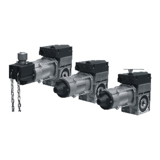
- Page 1 SDL - SDEL - SWL - SWEL Gearmotors for sectional doors Instructions and information for installation and use English – 1...
-
Page 2: Table Of Contents
TABLE OF CONTENTS GENERAL INFORMATION.......................3 SAFETY STANDARDS........................3 INSTALLATION RULES........................3 GENERAL DANGERS AND SAFETY STANDARDS..............4 ASSEMBLY INSTRUCTIONS / FIXING THE MECHANISM............4 MANUAL EMERGENCY RELEASE....................4 LIMIT SWITCH SETTING........................5 STAR-DELTA VOLTAGE CONNECTION..................5 ANNUAL CHECK..........................6 TECHNICAL SPECIFICATIONS......................6 FIGURES..........................7 FIGURES..........................8 FIGURES..........................9 GEARMOTOR CONNECTION CABLE...................10-12 DIMENSIONED GEARMOTOR DRAWINGS................13-18 TRANSPORT / STORAGE / DISPOSAL..................19 TECHNICAL ASSISTANCE / SPARE PARTS / ACCESSORIES............19 DECLARATION OF CONFORMITY (Declaration of manufacturer)........19... -
Page 3: General Information
In the case of doubt, immediately interrupt • The automatic main doors with built-in pedestrian service the installation operations and contact the Nice Technical door are to be equipped with a control system that Assistance Department to receive explanations and prevents the motor from starting when the pedestrian clarifications. -
Page 4: General Dangers And Safety Standards
- On doors not balanced with weights, the brake is to be released GENERAL DANGER WARNINGS AND PREVENTIVE only for checking purposes with the door in the low position for SAFETY safety reasons. - An undesirable brake release must be prevented with an adequate According to the VDE 0113 booklet, the emergency stop check (measurement) on site. -
Page 5: Limit Switch Setting
2. Electronic limit switches (transducer absolute value), type A and type B (fig. 10 and 11) LIMIT SWITCH SETTING The door must be balanced in all positions when assembling and The EES electronic limit switch is a positioning switch with absolute value for rolling shutters, doors and main doors. -
Page 6: Annual Check
TECHNICAL SPECIFICATIONS NOTE: all the technical characteristics indicated refer to a temperature falling between -5°C and +40°C. • Nice reserves the right to change all the modifications to the product it deems necessary at any time, but keeping the functions and intended use unaltered. -
Page 7: Figures
Assembly of gearmotor shaft using Application of support for suspended or fixing screw or ring vertical assembly Motor Motor Decke Roof Grün Green English – 7... -
Page 8: Figures
Emergency release chain Gearmotor with interlocking 8 white Additional limit switch 2 CLOSE Optional 7 green Additional limit switch 2 OPEN 6 white Additional limit switch 1 CLOSE 5 green Additional limit switch 1 OPEN 4 red Safety limit switch CLOSE 3 white Limit switch CLOSE 2 red Safety limit switch OPEN 1 green Limit switch OPEN... -
Page 9: Figures
Electronic limit switch A type Wires 1, 2 and 3 Control connection cable 9. Use only if the chain slips! Turn the handle clockwise until the operational efficiency of the chain is restored! Six-pole plug Control connection cable Electronic limit switch Station Gearmotor Motor... -
Page 10: Gearmotor Connection Cable
CONNECTION CABLE FOR GEARMOTORS EQUIPPED WITH MECHANICAL LIMIT SWITCH WITH SCREENING 10 – English... - Page 11 CONNECTION CABLE FOR GEARMOTORS EQUIPPED WITH MECHANICAL LIMIT SWITCH WITH SCREENING English – 11...
- Page 12 CONNECTION CABLE FOR GEARMOTORS EQUIPPED WITH MECHANICAL LIMIT SWITCH WITH SCREENING 12 – English...
-
Page 13: Dimensioned Gearmotor Drawings
DIMENSIONED DRAWINGS OF GEARMOTORS FOR SECTIONAL DOORS 230V gearmotors SWL 0.20-20 KU SWEL 0.20-20 SWL 0.20-20 KE Ø 10mm English – 13... - Page 14 Wiring diagram for 230V single phase motor DIMENSIONED DRAWINGS OF GEARMOTORS FOR SECTIONAL DOORS UST1 Anschluss X11 Anschluss an UST1 Platine U V W 20uF Zusatzkabel gelb blau gelb/grün schwarz blau braun 16uF L1 L2 L3 14 – English...
- Page 15 DIMENSIONED DRAWINGS OF GEARMOTORS FOR SECTIONAL DOORS Gearmotor with interlocking release SDEL 0.37-24 SDEL 0.37-20 SDEL 0.55-20 Only with the 0.55-20 gearmotors Hollow shaft diameter: 25.4 or 31.75 mm. When assembling gearmotors with 31.75 mm diameter shaft from the left, the tab is to be blocked only with a fixing ring because using a screw could break the shaft.
- Page 16 DIMENSIONED DRAWINGS OF GEARMOTORS FOR SECTIONAL DOORS Gearmotors with handle SDL 0.37-24 KU SDL 0.37-20 KU SDL 0.55-20 KU Ø 10mm Only with the 0.55-20 gearmotors Hollow shaft diameter: 25.4 or 31.75 mm. When assembling gearmotors with 31.75 mm diameter shaft from the left, the tab is to be blocked only with a fixing ring because using a screw could break the shaft.
- Page 17 DIMENSIONED DRAWINGS OF GEARMOTORS FOR SECTIONAL DOORS Gearmotors with light chain SDL 0.37-20 KE SDL 0.37-24 KE SDL 0.55-20 KE Only with the 0.55-20 gearmotors Hollow shaft diameter: 25.4 or 31.75 mm. When assembling gearmotors with 31.75 mm diameter shaft from the left, the tab is to be blocked only with a fixing ring because using a screw could break the shaft.
- Page 18 DIMENSIONED DRAWINGS OF GEARMOTORS FOR SECTIONAL DOORS Gearmotors with manual emergency release handle SDL 0.37-24 KE2 SDL 0.37-20 KE2 SDL 0.55-20 KE2 Only with the 0.55-20 gearmotors Hollow shaft diameter: 25.4 or 31.75 mm. When assembling gearmotors with 31.75 mm diameter shaft from the left, the tab is to be blocked only with a fixing ring because using a screw could break the shaft.
-
Page 19: Transport / Storage / Disposal
For disposal, it is necessary to separate design level, or reflect on safety. − metals NICE declines all liability and disclaims any warranty whatsoever − plastic elements for damages, if any, caused by non-original spare parts and/or −... - Page 20 Note - The content of this declaration corresponds to the declaration at the last available version of the document filed in the offices of Nice S.p.A. prior to the printing of this manual. This text has been adapted to meet editorial requirements. A copy of the original declaration may be requested from Nice S.p.a.
Need help?
Do you have a question about the SD and is the answer not in the manual?
Questions and answers