
Subscribe to Our Youtube Channel
Related Manuals for Beckhoff EtherCAT EL6752


Summary of Contents for Beckhoff EtherCAT EL6752
- Page 1 Documentation EL6752 Master/Slave Terminal for DeviceNet Version: Date: 2018-12-11...
-
Page 3: Table Of Contents
6 Parameterization and commissioning .................... 32 CoE Interface........................... 32 General notes for setting the watchdog ................... 36 EtherCAT State Machine ......................... 38 TwinCAT System Manager...................... 41 Beckhoff DeviceNet Bus Coupler .................... 51 General DeviceNet device ....................... 56 6.6.1 Integrating a DeviceNet device with EDS file .............. 56 6.6.2 Integrating a DeviceNet device without EDS file ............. - Page 4 DeviceNet slave device / EL6752-0010 - MacState ............ 86 7.3.2 DeviceNet slave device / EL6752-0010 - DiagFlag ............ 88 7.3.3 Beckhoff DeviceNet slave device - CouplerState ............ 89 EL6752/-0010 - ADS Error Codes .................... 90 DeviceNet / CAN Trouble Shooting .................... 94 8 Appendix .............................. 97 UL notice ............................ 97...
-
Page 5: Foreword
The TwinCAT Technology is covered, including but not limited to the following patent applications and patents: EP0851348, US6167425 with corresponding applications or registrations in various other countries. ® EtherCAT is registered trademark and patented technology, licensed by Beckhoff Automation GmbH, Germany. Copyright © Beckhoff Automation GmbH & Co. KG, Germany. -
Page 6: Safety Instructions
All the components are supplied in particular hardware and software configurations appropriate for the application. Modifications to hardware or software configurations other than those described in the documentation are not permitted, and nullify the liability of Beckhoff Automation GmbH & Co. KG. Personnel qualification This description is only intended for trained specialists in control, automation and drive engineering who are familiar with the applicable national standards. -
Page 7: Documentation Issue Status
• Corrections and addenda, first publication • Corrections and addenda • Preliminary version for internal use Version identification of EtherCAT devices Designation A Beckhoff EtherCAT device has a 14-digit designation, made up of • family key • type • version • revision... - Page 8 Production lot/batch number/serial number/date code/D number The serial number for Beckhoff IO devices is usually the 8-digit number printed on the device or on a sticker. The serial number indicates the configuration in delivery state and therefore refers to a whole production batch, without distinguishing the individual modules of a batch.
-
Page 9: Fig. 1 El5021 El Terminal, Standard Ip20 Io Device With Serial/ Batch Number And Revision Id (Since 2014/01)
Foreword Examples of markings Fig. 1: EL5021 EL terminal, standard IP20 IO device with serial/ batch number and revision ID (since 2014/01) Fig. 2: EK1100 EtherCAT coupler, standard IP20 IO device with serial/ batch number Fig. 3: CU2016 switch with serial/ batch number EL6752 Version: 2.1... -
Page 10: Fig. 4 El3202-0020 With Serial/ Batch Number 26131006 And Unique Id-Number 204418
Foreword Fig. 4: EL3202-0020 with serial/ batch number 26131006 and unique ID-number 204418 Fig. 5: EP1258-00001 IP67 EtherCAT Box with batch number/ date code 22090101 and unique serial number 158102 Fig. 6: EP1908-0002 IP67 EtherCAT Safety Box with batch number/ date code 071201FF and unique serial number 00346070 Fig. 7: EL2904 IP20 safety terminal with batch number/ date code 50110302 and unique serial number 00331701... -
Page 11: Fig. 8 Elm3604-0002 Terminal With Unique Id Number (Qr Code) 100001051 And Serial/ Batch Num- Ber 44160201
Foreword Fig. 8: ELM3604-0002 terminal with unique ID number (QR code) 100001051 and serial/ batch number 44160201 EL6752 Version: 2.1... -
Page 12: Product Overview
Master and slave terminals for DeviceNet The master and slave terminals for DeviceNet correspond to the FC5201 PCI card from Beckhoff. Thanks to the connection via EtherCAT, no PCI slots are required in the PC. Within an EtherCAT terminal network, the terminal enables the integration of any DeviceNet devices. -
Page 13: Technical Data
Product overview Technical data Technical data EL6752-0000 EL6752-0010 Bus system DeviceNet Variante Master Slave Number of fieldbus channels Data transfer rate 125, 250 or 500 kbaud Bus interface Open style 5-pin connector according to DeviceNet specification, galvanically isolated; card comes with connector. Bus devices maximum 63 slaves Communication... -
Page 14: Basic Devicenet Principles
Basic DeviceNet principles Basic DeviceNet principles Introduction to the system DeviceNet is an open system based on CAN. CAN was developed some years ago by R. Bosch for data transmission in motor vehicles. Millions of CAN chips are now in use. A disadvantage for application in automation is that CAN does not contain definitions for the application layer. -
Page 15: Mounting And Cabling
• Each assembly must be terminated at the right hand end with an EL9011 or EL9012 bus end cap, to en- sure the protection class and ESD protection. Fig. 12: Spring contacts of the Beckhoff I/O components Recommended mounting rails Terminal Modules und EtherCAT Modules of KMxxxx and EMxxxx series, same as the terminals of the EL66xx and EL67xx series can be snapped onto the following recommended mounting rails: •... - Page 16 Mounting and cabling Fixing of mounting rails The locking mechanism of the terminals and couplers extends to the profile of the mounting rail. At the installation, the locking mechanism of the components must not come into conflict with the fixing bolts of the mounting rail.
-
Page 17: Mounting And Demounting - Terminals With Front Unlocking
Mounting and cabling • In the case 32 and 64 channel terminal modules (KMxxx4 and KMxxx8 or EMxxx4 and EMxxx8) you now lever the second unlatching hook on the right-hand side of the terminal module upwards in the same way. •... - Page 18 Mounting and cabling Fixing of mounting rails The locking mechanism of the terminals and couplers extends to the profile of the mounting rail. At the installation, the locking mechanism of the components must not come into conflict with the fixing bolts of the mounting rail.
-
Page 19: Devicenet Wiring
Mounting and cabling • Pull (4) the terminal module away from the mounting surface. Avoid canting of the module; you should stabilize the module with the other hand, if required. DeviceNet wiring 4.5.1 CAN / DeviceNet topology CAN/DeviceNet is a 2-wire bus system, to which all participating devices are connected in parallel (i.e. using short drop lines) (Fig. -
Page 20: Bus Length
Mounting and cabling Fig. 14: Low interference through difference levels 4.5.2 Bus length The maximum length of a CAN bus is primarily limited by the signal propagation delay. The multi-master bus access procedure (arbitration) requires signals to reach all the nodes at effectively the same time (before the sampling within a bit period). -
Page 21: Star Hub (Multiport Tap)
Shorter drop line lengths must be maintained when passive distributors ("multiport taps"), such as the Beckhoff ZS5052-4500 Distributor Box. The following table indicates the maximum drop line lengths and the maximum length of the trunk line (without the drop lines): Guide values The following values are recommended by BECKHOFF. -
Page 22: Can Cable
Mounting and cabling 4.5.5 CAN cable Screened twisted-pair cables (2x2) with a characteristic impedance of between 108 and 132 Ohm is recommended for the CAN wiring. If the CAN transceiver’s reference potential (CAN ground) is not to be connected, the second pair of conductors can be omitted. (This is only recommended for networks of small physical size with a common power supply for all the participating devices). -
Page 23: Cable Colours And Pin Assignment
Mounting and cabling 4.5.7 Cable colours and pin assignment Fig. 17: Pin assignment (top view EL6752) Suggested method of using the Beckhoff CAN cable on Bus Terminal and Fieldbus Box: EL6752 assignment ZB5200 cable color V+ (24 V) CAN High white... -
Page 24: Fig. 18 Recommended Distances For Standard Installation Position
Mounting and cabling Fig. 18: Recommended distances for standard installation position Compliance with the distances shown in Fig. “Recommended distances for standard installation position” is recommended. Other installation positions All other installation positions are characterized by different spatial arrangement of the mounting rail - see Fig “Other installation positions”. -
Page 25: Fig. 19 Other Installation Positions
Mounting and cabling Fig. 19: Other installation positions EL6752 Version: 2.1... -
Page 26: Positioning Of Passive Terminals
Mounting and cabling Positioning of passive Terminals Hint for positioning of passive terminals in the bus terminal block EtherCAT Terminals (ELxxxx / ESxxxx), which do not take an active part in data transfer within the bus terminal block are so called passive terminals. The passive terminals have no current consump- tion out of the E-Bus. -
Page 27: Atex - Special Conditions (Standard Temperature Range)
80°C at the wire branching points, then cables must be selected whose tempera- ture data correspond to the actual measured temperature values! • Observe the permissible ambient temperature range of 0 to 55°C for the use of Beckhoff fieldbus compo- nents standard temperature range in potentially explosive areas! •... -
Page 28: Devicenet Communication
The BECKHOFF DeviceNet devices have a powerful implementation of the protocol. Through active participation in the ODVA's technical committees, BECKHOFF are contributing to the further development of this bus system, and has in this way itself gathered profound DeviceNet expertise. - Page 29 Diagnostics The extensive diagnostic functions of the BECKHOFF DeviceNet devices allow rapid fault localisation. The diagnostic messages are transmitted over the bus and collated by the master. The status of the network connection, the device status, the status of the inputs and outputs and of the power supply are displayed by LEDs.
-
Page 30: Explicit Messages
DeviceNet communication Explicit messages Program example „ExplMessageEditor“: https://infosys.beckhoff.com/content/1033/el6752/Resources/ zip/5979571979.zip With the following ADS commands you can use EL6752 to send explicit messages. GET_ATTRIBUTE_SINGLE via ADSRead Data Transfer SET_ATTRIBUTE_SINGLE via ADSWrite Data Transfer COMMON SERVICE via ADSReadWrite Data Transfer For the ADS NetID and the port, the values from the system manager are to be used. -
Page 31: Fig. 24 Using Ads Netid And Port From System Manager
DeviceNet communication IDXOFFS:= IOff_ADSWrite, LEN:= ADSWriteLen, SRCADDR:= ADR(SetAttributeWriteData[0]), WRITE:= ADSWriteCommand, TMOUT:= T#5s, BUSY=> ADSWriteBusy, ERR=> ADSWriteErr, ERRID=> ADSWriteErrID); Fig. 24: Using ADS NetID and Port from System Manager EL6752 Version: 2.1... -
Page 32: Parameterization And Commissioning
Parameterization and commissioning Parameterization and commissioning CoE Interface General description The CoE interface (CANopen over EtherCAT) is used for parameter management of EtherCAT devices. EtherCAT slaves or the EtherCAT master manage fixed (read only) or variable parameters which they require for operation, diagnostics or commissioning. CoE parameters are arranged in a table hierarchy. -
Page 33: Fig. 25 "Coe Online " Tab
Data management If slave CoE parameters are modified online, Beckhoff devices store any changes in a fail-safe manner in the EEPROM, i.e. the modified CoE parameters are still available after a restart. The situation may be different with other manufacturers. -
Page 34: Fig. 26 Startup List In The Twincat System Manager
Changes in the local CoE list of the terminal are lost if the terminal is replaced. If a terminal is re- placed with a new Beckhoff terminal, it will have the default settings. It is therefore advisable to link all changes in the CoE list of an EtherCAT slave with the Startup list of the slave, which is pro- cessed whenever the EtherCAT fieldbus is started. -
Page 35: Fig. 27 Offline List
Parameterization and commissioning Fig. 27: Offline list • If the slave is online ◦ The actual current slave list is read. This may take several seconds, depending on the size and cycle time. ◦ The actual identity is displayed ◦ The firmware and hardware version of the equipment according to the electronic information is displayed ◦... -
Page 36: General Notes For Setting The Watchdog
This is generally written as 0x80n0. Detailed information on the CoE interface can be found in the EtherCAT system documentation on the Beckhoff website. General notes for setting the watchdog ELxxxx terminals are equipped with a safety feature (watchdog) that switches off the outputs after a specifiable time e.g. -
Page 37: Fig. 29 Ethercat Tab -> Advanced Settings -> Behavior -> Watchdog
Parameterization and commissioning Fig. 29: EtherCAT tab -> Advanced Settings -> Behavior -> Watchdog Notes: • the multiplier is valid for both watchdogs. • each watchdog has its own timer setting, the outcome of this in summary with the multiplier is a resulting time. -
Page 38: Ethercat State Machine
Parameterization and commissioning Example "Set SM watchdog" This checkbox enables manual setting of the watchdog times. If the outputs are set and the EtherCAT communication is interrupted, the SM watchdog is triggered after the set time and the outputs are erased. This setting can be used for adapting a terminal to a slower EtherCAT master or long cycle times. -
Page 39: Fig. 30 States Of The Ethercat State Machine
Parameterization and commissioning Fig. 30: States of the EtherCAT State Machine Init After switch-on the EtherCAT slave in the Init state. No mailbox or process data communication is possible. The EtherCAT master initializes sync manager channels 0 and 1 for mailbox communication. Pre-Operational (Pre-Op) During the transition between Init and Pre-Op the EtherCAT slave checks whether the mailbox was initialized correctly. - Page 40 Parameterization and commissioning Boot In the Boot state the slave firmware can be updated. The Boot state can only be reached via the Init state. In the Boot state mailbox communication via the file access over EtherCAT (FoE) protocol is possible, but no other mailbox communication and no process data communication.
-
Page 41: Twincat System Manager
Parameterization and commissioning TwinCAT System Manager The TwinCAT System Manager tool is used for the configuration of the EL6752 DeviceNet master/slave terminal. The System Manager provides a representation of the number of programs of the TwinCat PLC systems, the configuration of the axis control and of the connected I/O channels as a structure, and organizes the mapping of the data traffic. -
Page 42: Fig. 32 Appending The Device "Devicenet Master El6752, Ethercat
Parameterization and commissioning Fig. 32: Appending the device "DeviceNet master EL6752, EtherCAT" "EL6752" tab Click on the "Device EL6752" in the TwinCAT tree and then on the EL6752 tab: Fig. 33: "EL6752" tab EtherCAT Terminal ID in the terminal network. MAC-ID Each DeviceNet device - master included - requires a unique station number referred to as MAC ID (Medium Access Identifier) - value range: 0...63. -
Page 43: Fig. 34 "Ads" Tab
Parameterization and commissioning Cycle time Displays the cycle time of the corresponding highest priority task. The display is updated when the mapping is generated. IO-Cycle Time Setting of the cycle time for the I/O connections. This value is the standard value for newly inserted boxes. Watchdog time Time until triggering of the watchdog Search... -
Page 44: Fig. 35 "Box States" Tab
Parameterization and commissioning ”Box States" tab Fig. 35: "Box states" tab Displays an overview of all current box statuses. EL6752-0010 - DeviceNet slave terminal In the system configuration tree structure right-click on I/O Devices and “Append device” to open the selection list of supported fieldbus cards. Select EL6752-0010 CANopenSlave. -
Page 45: Fig. 37 Appending The Box "Devicenet Slave El6752, Ethercat
Parameterization and commissioning Fig. 37: Appending the box "DeviceNet slave EL6752, EtherCAT" Selecting the I/O device for the EL6752-0010 in the tree structure opens a dialog with various configuration options: “EL6752-0010” tab Fig. 38: “EL6752-0010” tab EtherCAT Terminal ID in the terminal network. MAC-ID Each DeviceNet device requires a unique station number referred to as MAC ID (Medium Access Identifier) - value range: 0...63. -
Page 46: Fig. 39 "Ads" Tab
Parameterization and commissioning Baud rate The baud rate is set here. Cycle time Displays the cycle time of the corresponding highest priority task. The display is updated when the mapping is generated. The network variables are updated with the cycle of this task. Watchdog time Time until the watchdog is triggered Search... -
Page 47: Fig. 40 "General" Tab, Box El6752-0010
Parameterization and commissioning Box EL6752-0010 tab: Fig. 40: "General" tab, Box EL6752-0010 DeviceNet IO modes The EL6752-0010 supports the DeviceNet modes cyclic polling, change of state / cyclic and bit strobe. The IO modes can be selected according to the DeviceNet specification. The DeviceNet IO mode cyclic polling is the default selection for the EL6752-0010: IO mode Input data length / bytes... -
Page 48: Fig. 41 Pre-Initialized Input And Output Data Lengths In Polling Mode
Parameterization and commissioning Fig. 41: Pre-initialized input and output data lengths in polling mode According to needs and the application, further input or output data can be appended by right-clicking (Fig. Adding further variables). Any data type can be selected: Fig. 42: Adding further variables The data length is converted to a byte stream according to the DeviceNet specification and displayed in the tab for the corresponding connection: Version: 2.1... - Page 49 Parameterization and commissioning Fig. 43: "Connection" tab showing connection type "Polling" and input and output parameters Maximum output data length The maximum data length per data direction is 255 bytes. The indicated input and output data lengths must be configured for the corresponding DeviceNet master. Bit strobe The IO mode bit strobe involves an 8-byte command from the master to the slaves.
- Page 50 Parameterization and commissioning Fig. 44: Display of output parameters in the TwinCAT tree for connection type "Bit strobe" Maximum output data length The maximum output data length is 8 bytes. The input data length is fixed. Since the communication settings are specified through the master no further settings are possible. Version: 2.1 EL6752...
-
Page 51: Beckhoff Devicenet Bus Coupler
Parameterization and commissioning Beckhoff DeviceNet Bus Coupler The Bus Coupler BK52xx and the IPxxx-B520 Fieldbus Box are used in the DeviceNet bus. The specific properties which distinguish them from other Bus Couplers and/or fieldbus box modules are then described below. - Page 52 Parameterization and commissioning Cycle time Sets the cycle time of the IO connection polling and bit strobe. The value is used as “Expected Packet Rate” attribute of the “Connection Object” according to the DeviceNet specification. Electronic Key Serves to check the devices within the network at the system StartUp. The electronic key is read from the devices at every system StartUp and compared with the saved configuration.
- Page 53 Parameterization and commissioning “Startup Attributes” tab Fig. 46: “Startup Attributes” tab The startup attributes are sent to the slave before the cyclic data exchange. The messages are sent before the actual IO data traffic. Use the “New” or “Edit” button for configuration: Fig. 47: Edit an attribute entry The attributes are initialized via Class/Instance/Attributes.
- Page 54 Parameterization and commissioning “ADS” tab Fig. 48: “ADS” tab The node (Bus Coupler) is assigned an ADS port to enable writing and reading of DeviceNet objects at runtime (e.g. from the PLC). It can be changed if required. A detailed description of explicit messages can be found in section “DeviceNet Communication”...
- Page 55 Parameterization and commissioning “Parameter” tab Fig. 49: “Parameter” tab The parameters read from the EDS file are shown under the “Parameters” tab. Parameters can be read, written and entered in the list of the startup parameters. “Diag” tab Fig. 50: "Diag" tab The “Diag”...
-
Page 56: General Devicenet Device
Parameterization and commissioning General DeviceNet device DeviceNet devices are integrated as general DeviceNet devices. Fig. 51: Adding a DeviceNet device (I/O Devices-> Device n (EL6752)->right-click-> Append Box...) 6.6.1 Integrating a DeviceNet device with EDS file If an EDS file is available for the DeviceNet to be integrated, it must be copied into the ..TwinCAT/IO/ DeviceNet directory. -
Page 57: Integrating A Devicenet Device Without Eds File
Parameterization and commissioning Fig. 53: Adding a box without EDS file Depending on the information contained in the EDS file a DeviceNet node will appear with or without Parameters tab. The IO mode and the corresponding data lengths are specified in the EDS file. 6.6.2 Integrating a DeviceNet device without EDS file A DeviceNet device without EDS file can be integrated via the "Miscellaneous"... - Page 58 Parameterization and commissioning Selection of the IO mode and the general configuration must then be carried out manually. DeviceNet IO modes For DeviceNet devices the EL6752 supports the DeviceNet modes cyclic polling, change of state / cyclic and bit strobe. The IO modes can be selected according to the DeviceNet specification. The DeviceNet IO mode cyclic polling is the default selection for the EL6752: IO mode Input data length / bytes...
- Page 59 Parameterization and commissioning Fig. 56: Add Variables The data length is converted to a byte stream according to the DeviceNet specification and displayed in the tab for the corresponding connection: Fig. 57: "Connection" tab showing connection type "Polling" and input and output parameters Maximum data length The maximum data length per data direction is 255 bytes.
-
Page 60: Parameterization Of A Devicenet Device
Parameterization and commissioning Bit strobe The IO mode bit strobe involves an 8-byte command from the master to the slaves. For each possible address/MAC ID (DeviceNet address space: 64) 1 bit of user data is allocated. The maximum length of the response message from the slave is 8 bytes. - Page 61 Parameterization and commissioning • “Diag” tab [} 64] "DeviceNet Node" tab Fig. 59: "DeviceNet Node" tab MAC-ID Sets the MAC ID, i.e. the device address of the DeviceNet device (between 0 and 63). This value must comply with the value set at the Bus Coupler and/or at the compact box. Cycle time Sets the cycle time of the IO connection polling and bit strobe.
- Page 62 Parameterization and commissioning Change of State / Cyclic Produced/Consumed Setting of the data content of the data transmitted via the change of state/cyclical IO connections. You can choose from digital data, analog data or both. The selection depends upon the BK52xx terminal arrangement.
- Page 63 Parameterization and commissioning Fig. 61: Edit an attribute entry The attributes are initialized via Class/Instance/Attributes. Note the “Value” specification in hexadecimal form. “ADS” tab Fig. 62: “ADS” tab The node (Bus Coupler) is assigned an ADS port to enable writing and reading of DeviceNet objects at runtime (e.g.
- Page 64 Parameterization and commissioning “Parameter” tab Fig. 63: “Parameter” tab The parameters read from the EDS file are shown under the “Parameters” tab. Parameters can be read, written and entered in the list of the startup parameters. “Diag” tab Fig. 64: "Diag" tab The “Diag”...
-
Page 65: Ethercat Description
Parameterization and commissioning EtherCAT description 6.7.1 Introduction The DeviceNet functionality and configuration options can be changed and parameterized depending on the different EtherCAT states. EtherCAT states The EtherCAT states (INIT, PREOP, SAFEOP, OP) have the following meaning according to the fieldbus- specific functions: EtherCAT state Meaning... - Page 66 Parameterization and commissioning The EtherCAT PDO mapping (EtherCAT objects 0x16yy, 0x1Ayy) and the PDO assignment (EtherCAT objects 0x1C12 [} 73], 0x1C13 [} 74]) can be read once the DeviceNet master parameters and the DeviceNet slave parameters have been written. The associated process image is then generated. Once the DeviceNet master parameters have been written via the EtherCAT object 0xF800 [} 76], the DeviceNet master registers itself in the network and carries out the Duplicate MAC ID check.
- Page 67 Parameterization and commissioning Once the DeviceNet slave parameters have been written via the EtherCAT object 0xF800 [} 81], the DeviceNet slave registers itself in the network and carries out the Duplicate MAC ID check. Starting the fieldbus During the EtherCAT state transition from PREOP to SAFEOP the DeviceNet slave starts the data communication, i.e.
- Page 68 Parameterization and commissioning Command taking the example of the TwinCAT AMS ADS Viewer Fig. 67: ADS command with the data 3C - MACId (60dec) and 01 - baud rate (500k) Reset Once the MAC ID and the baud rate have been set using the ADS command, the terminal stores the information persistently.
- Page 69 Parameterization and commissioning Fig. 68: Example of start-up CMD (0x8000:01; 0xF800:01 and 0xF800:02) that are ignored by the slave terminal after successfully setting the MACId and baud rate using ADS ADS command (reset) IDXGRP=0x1F480 Index Offset 0x00 LEN=6 DATA[0]=0 DATA[1]=0 DATA[2]=0 DATA[3]=0 DATA[4]=0 DATA[5]=0 ...
-
Page 70: Object Description And Parameterization
EtherCAT XML Device Description The display matches that of the CoE objects from the EtherCAT XML Device Description. We rec- ommend downloading the latest XML file from the download area of the Beckhoff website and in- stalling it according to installation instructions. - Page 71 Parameterization and commissioning 6.7.2.1.1 Objects for the parameterization Index 8000-803E configuration data Index (hex) Name Meaning Data type Flags Default 8000+n*16: Configuration data (for each module one object is defined (0 ≤ n < maximum UINT8 0x33 (51 number of modules)) (8000+n*16) MAC ID DeviceNet device address (see DeviceNet specification) UINT16...
- Page 72 Parameterization and commissioning Index (hex) Name Meaning Data type Flags Default (8000+n*16 Electronic Key Electronic key bit mask: UINT16 0x0100 ):2A (256 Bit 0: Check Vendor Id Bit 1: Check DeviceType Bit 2: Check Product Code Bit 3: Check Revision Bit 4: reserved(0) Bit 5: reserved(0) Bit 6: reserved(0)
- Page 73 Parameterization and commissioning Index 1018 Identity Index (hex) Name Meaning Data type Flags Default 1018:0 Identity Information for identifying the slave UINT8 0x04 (4 1018:01 Vendor ID Vendor ID of the EtherCAT slave UINT32 0x00000002 1018:02 Product code Product code of the EtherCAT slave UINT32 0x1A603052 (442511442...
- Page 74 Parameterization and commissioning Index 1C13 TxPDO assign Index (hex) Name Meaning Data type Flags Default 1C13:0 TxPDO assign PDO Assign Inputs UINT8 0x01 (1 1C13:01 allocated TxPDO (contains the index of the associated TxPDO mapping object) 1C13:FF allocated TxPDO (contains the index of the associ- ated TxPDO mapping object) Profile-specific objects (0x6000-0xFFFF) The profile-specific objects have the same meaning for all EtherCAT slaves that support the profile 5001.
- Page 75 Parameterization and commissioning Index F000 Modular device profile Index (hex) Name Meaning Data type Flags Default F000:0 Modular device profile General information for the modular device profile UINT8 0x02 (2 F000:01 Module index dis- Index distance of the objects of the individual channels UINT16 0x0010 (16 tance...
- Page 76 EtherCAT XML Device Description The display matches that of the CoE objects from the EtherCAT XML Device Description. We rec- ommend downloading the latest XML file from the download area of the Beckhoff website and in- stalling it according to installation instructions.
- Page 77 Parameterization and commissioning 6.7.2.2.1 Objects for the parameterization Index 8000 configuration data Index (hex) Name Meaning Data type Flags Default 8000:0 Configuration Data Max. Subindex UINT8 0x33 (51 8000:01 MAC ID DeviceNet device address (see DeviceNet specification) UINT16 0x0000 (0 8000:03 ProductName Product name...
- Page 78 Parameterization and commissioning 6.7.2.2.2 Objects for internal settings Standard objects (0x1000-0x1FFF) The standard objects have the same meaning for all EtherCAT slaves. Index 1000 Device type Index (hex) Name Meaning Data type Flags Default 1000:0 Device type Device type of the EtherCAT slave: The Lo-Word con- UINT32 0x145A1389 tains the CoE profile used (5001).
- Page 79 Parameterization and commissioning Index 1A01 DNM TxPDO-Map Device Index (hex) Name Meaning Data type Flags Default 1A01:0 DNM TxPDO-Map PDO Mapping TxPDO 2 UINT8 0x09 (9 Device 1A01:01 SubIndex 001 1. PDO Mapping entry (object 0xF100 (DeviceNet sta- UINT32 0xF100:01, 8 tus), entry 0x01 (Communication status)) 1A01:02 SubIndex 002...
- Page 80 Parameterization and commissioning Index 6001 COS Produced Data Index (hex) Name Meaning Data type Flags Default 6001:0 COS Produced Data Output data of the change of state connection UINT8 0x01 (1 6001:01 6001:01 Index 7000 Poll Consumed Data Index (hex) Name Meaning Data type Flags...
- Page 81 Parameterization and commissioning Index F101 Network status Index (hex) Name Meaning Data type Flags Default F101:0 Network status Max. Subindex UINT8 0x11 (17 F101:01 Device status 0: RUN MODE UINT8 0x00 (0 1: IDLE MODE 2: Duplicate MacId Check failed, MAC ID used 3: Status: Selftest 4: Status: Standby 5: Status:Major Recoverable Fault...
-
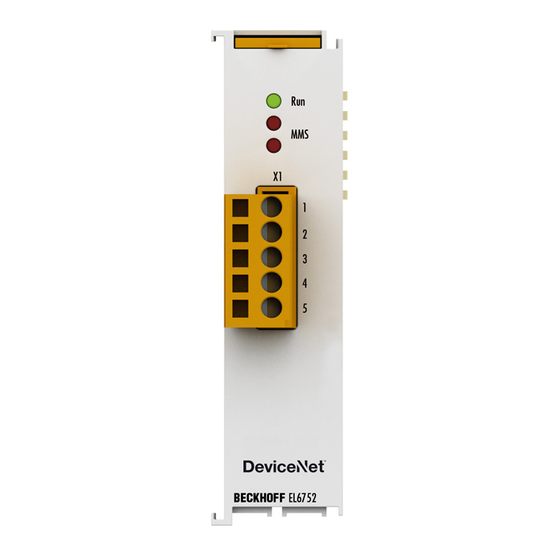
Page 82: Error Handling And Diagnostics
Error handling and diagnostics Error handling and diagnostics EL6752 - LED description Fig. 70: LEDs LED behaviour The LEDs facilitate diagnosing of the main terminal states: EL6752-0000 (DeviceNet master terminal) Colours Meaning green This LED indicates the terminal's operating state: State of the EtherCAT State Machine: INIT = initialization of the terminal;... - Page 83 Error handling and diagnostics EL6752-0010 (DeviceNet slave terminal) Color Meaning green This LED indicates the terminal's operating state: State of the EtherCAT State Machine: INIT = initialization of the terminal; BOOTSTRAP = function for terminal firmware updates flashing State of the EtherCAT State Machine: PREOP = function for mailbox communication and different standard-settings set Single flash State of the EtherCAT State Machine: SAFEOP = verification of the sync manager channels and the distributed clocks.
-
Page 84: El6752/-0010 Diagnostics
Error handling and diagnostics EL6752/-0010 diagnostics The EL6752/-0010 feature various diagnostic variables that describe the state of the terminal and the DeviceNet and can be linked in the PLC: We recommend monitoring the following process data during each cycle: • WcState: if ≠ 0, this EtherCAT device does not take part in the process data traffic •... -
Page 85: El6752/-0010 - State
Error handling and diagnostics 7.2.2 EL6752/-0010 - State The diagnostic state variable indicates the current EtherCAT state of the EL6752/-0010. Fig. 72: State diagnostic variable in the TwinCAT tree State 0x___1 = Slave in 'INIT' state 0x___2 = Slave in 'PREOP' state 0x___3 = Slave in 'BOOT' state 0x___4 = Slave in 'SAFEOP' state 0x___8 = Slave in 'OP' state... -
Page 86: El6752/-0010 - Error / Diagflag
• MacState: if ≠ 0, this DeviceNet device is not participating correctly in the process data traffic • CouplerState: for Beckhoff Bus Couplers, the terminal communication of the Bus Coupler may be disturbed or diagnostic data may be present if ≠ 0 7.3.1... - Page 87 Error handling and diagnostics Fig. 74: MacState in the TwinCAT tree MacState 0 = No error 1 = Station deactivated 2 = Station not exists 18 = Station ready 40 = Heartbeat Message not received 41 = Shutdown Message received 42 = Electronic Key Fault: Vendor Id 43 = Electronic Key Fault: Device Type 44 = Electronic Key Fault: Product Code 45 = Electronic Key Fault: Revision...
-
Page 88: Devicenet Slave Device / El6752-0010 - Diagflag
Error handling and diagnostics 7.3.2 DeviceNet slave device / EL6752-0010 - DiagFlag The DiagFlag indicates pending diagnostic data. Pending diagnostic data can be read via an AdsRead command. Fig. 75: DiagFlag in the TwinCAT tree DiagFlag 0 = no diagnostic data are pending 1 = diagnostic data are pending and can be read via AdsRead services Version: 2.1 EL6752... -
Page 89: Beckhoff Devicenet Slave Device - Couplerstate
7.3.3 Beckhoff DeviceNet slave device - CouplerState The CouplerState provides information on the terminal bus communication of the Beckhoff Bus Coupler. This information is available for Beckhoff BK52x0 Bus Couplers, devices from the IPxxxx-B520 IP Box-family and the IP Link family. -
Page 90: El6752/-0010 - Ads Error Codes
Error handling and diagnostics EL6752/-0010 - ADS Error Codes The ADS error codes have the following meaning: Error Description Error during ADS/AMS data exchange 0x1001 Insufficient memory for AMS command 0x1101 Incorrect data length at StartFieldbus 0x1102 Incorrect DeviceState at StartFieldbus 0x1103 Device cannot change from INIT to RUN 0x1104... - Page 91 Error handling and diagnostics Error Description Error during ADS/AMS data exchange 0x1120 Box parameters cannot be read 0x1121 Cdl parameters cannot be read 0x1122 DeleteBox or DeleteCdl only with AdsWrite 0x1123 ReadBox only possible in STOP state 0x1124 Incorrect IndexOffset at ReadBox 0x1125 Incorrect data length at ReadBox 0x1126...
- Page 92 Error handling and diagnostics Error Description Error during ADS/AMS data exchange 0x1310 DeleteCdl: CDL is not stopped 0x1311 AddCdl: Insufficient memory for asynchronous transmit list 0x1312 AddCdl: Insufficient memory for synchronous receive list 0x1313 AddCdl: Insufficient memory for asynchronous receive list 0x1316 AddCdl: Insufficient memory for synchronous receive list 0x1318...
- Page 93 Error handling and diagnostics Error Description Error during ADS/AMS data exchange 0x1701 AddDeviceNotification: Length of device diagnostic data to small 0x1702 AddDeviceNotification: Length of device diagnostic data to large 0x1703 AddDeviceNotification: Length of box diagnostic data to small 0x1704 AddDeviceNotification: Length of box diagnostic data to large 0x1705 AddDeviceNotification: Box is not defined 0x1706...
-
Page 94: Devicenet / Can Trouble Shooting
Error handling and diagnostics DeviceNet / CAN Trouble Shooting Error Frames One sign of errors in the CAN wiring, the address assignment or the setting of the baud rate is an increased number of error frames: the diagnostic LEDs then show Warning Limit exceeded or Bus-off state entered. DeviceNet / CAN network analysis CAN warning limit exceeded, passive error or bus-off state are indicated first of all at the node that has detected the most errors. - Page 95 At all connecting points, branches and so forth the screen of the CAN cable (and possibly the CAN GND) must also be connected, as well as the signal leads. In the Beckhoff IP20 Bus Couplers, the screen is grounded for high frequencies via an R/C element.
- Page 96 DeviceNet experts - the Beckhoff support team [} 111] can help here. A free channel on a Beckhoff FC5102 CANopen PCI card is appropriate for such a trace - Beckhoff make the necessary trace software available on the internet. Alternatively, it is of course possible to use a normal commercial CAN analysis tool.
-
Page 97: Appendix
Beckhoff EtherCAT modules are intended for use with Beckhoff’s UL Listed EtherCAT Sys- tem only. Examination For cULus examination, the Beckhoff I/O System has only been investigated for risk of fire and electrical shock (in accordance with UL508 and CSA C22.2 No. 142). For devices with Ethernet connectors Not for connection to telecommunication circuits. -
Page 98: Ethercat Al Status Codes
Note • It is recommended to use the newest possible firmware for the respective hardware. • Beckhoff is not under any obligation to provide customers with free firmware updates for delivered products. NOTE Risk of damage to the device! Pay attention to the instructions for firmware updates on the separate page [} 99]. -
Page 99: Firmware Update El/Es/Em/Epxxxx
Appendix Firmware Update EL/ES/EM/EPxxxx This section describes the device update for Beckhoff EtherCAT slaves from the EL/ES, EM, EK and EP series. A firmware update should only be carried out after consultation with Beckhoff support. Storage locations An EtherCAT slave stores operating data in up to 3 locations: •... -
Page 100: Device Description Esi File/Xml
The device revision is closely linked to the firmware and hardware used. Incompatible combinations lead to malfunctions or even final shutdown of the device. Corresponding updates should only be carried out in consultation with Beckhoff support. Display of ESI slave identifier... - Page 101 Appendix Fig. 79: Scan the subordinate field by right-clicking on the EtherCAT device If the found field matches the configured field, the display shows Fig. 80: Configuration is identical otherwise a change dialog appears for entering the actual data in the configuration. Fig. 81: Change dialog In this example in Fig.
- Page 102 Appendix Changing the ESI slave identifier The ESI/EEPROM identifier can be updated as follows under TwinCAT: • Trouble-free EtherCAT communication must be established with the slave. • The state of the slave is irrelevant. • Right-clicking on the slave in the online display opens the EEPROM Update dialog, Fig. EEPROM Update Fig. 82: EEPROM Update The new ESI description is selected in the following dialog, see Fig.
-
Page 103: Firmware Explanation
• offline: The EtherCAT Slave Information ESI/XML may contain the default content of the CoE. This CoE directory can only be displayed if it is included in the ESI (e.g. "Beckhoff EL5xxx.xml"). The Advanced button must be used for switching between the two views. -
Page 104: Updating Controller Firmware *.Efw
Switch to the Online tab to update the controller firmware of a slave, see Fig. Firmware Update. Fig. 85: Firmware Update Proceed as follows, unless instructed otherwise by Beckhoff support. Valid for TwinCAT 2 and 3 as EtherCAT master. • Switch TwinCAT system to ConfigMode/FreeRun with cycle time >= 1 ms (default in ConfigMode is 4 ms). -
Page 105: Fpga Firmware *.Rbf
Appendix • Switch EtherCAT Master to PreOP • Switch slave to INIT (A) • Switch slave to BOOTSTRAP • Check the current status (B, C) • Download the new *efw file (wait until it ends). A pass word will not be neccessary usually. •... - Page 106 Appendix Fig. 86: FPGA firmware version definition If the column Reg:0002 is not displayed, right-click the table header and select Properties in the context menu. Fig. 87: Context menu Properties The Advanced Settings dialog appears where the columns to be displayed can be selected. Under Diagnosis/Online View select the '0002 ETxxxx Build' check box in order to activate the FPGA firmware version display.
- Page 107 Older firmware versions can only be updated by the manufacturer! Updating an EtherCAT device The following sequence order have to be met if no other specifications are given (e.g. by the Beckhoff support): • Switch TwinCAT system to ConfigMode/FreeRun with cycle time >= 1 ms (default in ConfigMode is 4 ms).
- Page 108 Appendix • In the TwinCAT System Manager select the terminal for which the FPGA firmware is to be updated (in the example: Terminal 5: EL5001) and click the Advanced Settings button in the EtherCAT tab: • The Advanced Settings dialog appears. Under ESC Access/E²PROM/FPGA click on Write FPGA button: Version: 2.1 EL6752...
-
Page 109: Simultaneous Updating Of Several Ethercat Devices
Appendix • Select the file (*.rbf) with the new FPGA firmware, and transfer it to the EtherCAT device: • Wait until download ends • Switch slave current less for a short time (don't pull under voltage!). In order to activate the new FPGA firmware a restart (switching the power supply off and on again) of the EtherCAT device is required. -
Page 110: Atex Documentation
Notes about operation of the Beckhoff terminal systems in potentially explosive ar- eas (ATEX) Pay also attention to the continuative documentation Notes about operation of the Beckhoff terminal systems in potentially explosive areas (ATEX) that is available in the download area of the Beckhoff homepage http:\\www.beckhoff.com! Abbreviations Abbreviation Description Controller Area Network. -
Page 111: Support And Service
Beckhoff's branch offices and representatives Please contact your Beckhoff branch office or representative for local support and service on Beckhoff products! The addresses of Beckhoff's branch offices and representatives round the world can be found on her internet pages: http://www.beckhoff.com You will also find further documentation for Beckhoff components there. - Page 112 EL6752 ............................Fig. 10 Example of DeviceNet in use....................... Fig. 11 Example of DeviceNet cabling..................... Fig. 12 Spring contacts of the Beckhoff I/O components................. Fig. 13 DeviceNet topology........................Fig. 14 Low interference through difference levels .................. Fig. 15 Drop line topology........................
- Page 113 Table of figures Fig. 42 Adding further variables....................... Fig. 43 "Connection" tab showing connection type "Polling" and input and output parameters ....Fig. 44 Display of output parameters in the TwinCAT tree for connection type "Bit strobe"....Fig. 45 ”BK52x0” tab..........................Fig.
- Page 114 Table of figures Fig. 87 Context menu Properties ......................106 Fig. 88 Dialog Advanced Settings ......................107 Fig. 89 Multiple selection and firmware update ..................109 Version: 2.1 EL6752...
Need help?
Do you have a question about the EtherCAT EL6752 and is the answer not in the manual?
Questions and answers