
Related Manuals for Beckhoff EL6731


Summary of Contents for Beckhoff EL6731
- Page 1 Documentation EL6731 Master/Slave terminal for PROFIBUS Version: Date: 2020-03-16...
-
Page 3: Table Of Contents
4 Basics communication ........................... 28 EtherCAT basics.......................... 28 General notes for setting the watchdog ................... 28 EtherCAT State Machine ......................... 30 CoE Interface........................... 32 5 Parameterization and commissioning .................... 37 EL6731 - PROFIBUS master terminal ..................... 37 5.1.1 PROFIBUS protocols....................... 37 5.1.2 PROFIBUS DP ........................ 38 5.1.3 PROFIBUS MC........................ - Page 4 Firmware Update EL/ES/EM/ELM/EPxxxx .................. 173 7.3.1 Device description ESI file/XML.................. 174 7.3.2 Firmware explanation .................... 177 7.3.3 Updating controller firmware *.efw................. 178 7.3.4 FPGA firmware *.rbf....................... 179 7.3.5 Simultaneous updating of several EtherCAT devices............ 183 Support and Service ........................ 184 Version: 2.8 EL6731...
-
Page 5: Foreword
EP1590927, EP1789857, EP1456722, EP2137893, DE102015105702 with corresponding applications or registrations in various other countries. ® EtherCAT is registered trademark and patented technology, licensed by Beckhoff Automation GmbH, Germany. Copyright © Beckhoff Automation GmbH & Co. KG, Germany. The reproduction, distribution and utilization of this document as well as the communication of its contents to others without express authorization are prohibited. -
Page 6: Safety Instructions
All the components are supplied in particular hardware and software configurations appropriate for the application. Modifications to hardware or software configurations other than those described in the documentation are not permitted, and nullify the liability of Beckhoff Automation GmbH & Co. KG. Personnel qualification This description is only intended for trained specialists in control, automation and drive engineering who are familiar with the applicable national standards. -
Page 7: Documentation Issue Status
• Technical data corrected • Revision, technical data amended • Preliminary version for internal use Version identification of EtherCAT devices Designation A Beckhoff EtherCAT device has a 14-digit designation, made up of • family key • type • version EL6731... - Page 8 Production lot/batch number/serial number/date code/D number The serial number for Beckhoff IO devices is usually the 8-digit number printed on the device or on a sticker. The serial number indicates the configuration in delivery state and therefore refers to a whole production batch, without distinguishing the individual modules of a batch.
-
Page 9: Fig. 1 El5021 El Terminal, Standard Ip20 Io Device With Serial/ Batch Number And Revision Id (Since 2014/01)
• Terminals with factory calibration certificate and other measuring terminals Examples of markings Fig. 1: EL5021 EL terminal, standard IP20 IO device with serial/ batch number and revision ID (since 2014/01) Fig. 2: EK1100 EtherCAT coupler, standard IP20 IO device with serial/ batch number EL6731 Version: 2.8... -
Page 10: Fig. 3 Cu2016 Switch With Serial/ Batch Number
Fig. 4: EL3202-0020 with serial/ batch number 26131006 and unique ID-number 204418 Fig. 5: EP1258-00001 IP67 EtherCAT Box with batch number/ date code 22090101 and unique serial number 158102 Fig. 6: EP1908-0002 IP67 EtherCAT Safety Box with batch number/ date code 071201FF and unique serial number 00346070 Version: 2.8 EL6731... -
Page 11: Fig. 7 El2904 Ip20 Safety Terminal With Batch Number/ Date Code 50110302 And Unique Serial Num- Ber 00331701
Foreword Fig. 7: EL2904 IP20 safety terminal with batch number/ date code 50110302 and unique serial number 00331701 Fig. 8: ELM3604-0002 terminal with unique ID number (QR code) 100001051 and serial/ batch number 44160201 EL6731 Version: 2.8... -
Page 12: Beckhoff Identification Code (Bic)
1.4.1 Beckhoff Identification Code (BIC) The Beckhoff Identification Code (BIC) is increasingly being applied to Beckhoff products to uniquely identify the product. The BIC is represented as a Data Matrix Code (DMC, code scheme ECC200), the content is based on the ANSI standard MH10.8.2-2016. - Page 13 Example of composite information from item 1 to 4 and 6. The data identifiers are marked in red for better display: An important component of the BIC is the Beckhoff Traceability Number (BTN, item no. 2). The BTN is a unique serial number consisting of eight characters that will replace all other serial number systems at Beckhoff in the long term (e.g.
-
Page 14: Product Overview
Ethernet, no PCI slots are required in the PC. The EL6731 can run the PROFIBUS protocol with all features; in the EtherCAT Terminal network it enables integration of any Profibus devices. Thanks to the in-house development of the PROFIBUS chip, the terminals are equipped with the latest version of the PROFIBUS technology –... -
Page 15: Technical Data
Weight approx. 70 g Permissible ambient temperature range -25 °C ... +60 °C (extended Temperature range) (for during operation EL6731-0010 from Hardware 17) Permissible ambient temperature range -40 °C ... +85 °C during storage Permissible relative humidity 95 %, no condensation Dimensions (W x H x D) approx. -
Page 16: Mounting And Wiring
• Each assembly must be terminated at the right hand end with an EL9011 or EL9012 bus end cap, to en- sure the protection class and ESD protection. Fig. 11: Spring contacts of the Beckhoff I/O components Recommended mounting rails Terminal Modules und EtherCAT Modules of KMxxxx and EMxxxx series, same as the terminals of the EL66xx and EL67xx series can be snapped onto the following recommended mounting rails: •... -
Page 17: Installation Positions
Other installation positions All other installation positions are characterized by different spatial arrangement of the mounting rail - see Fig “Other installation positions”. The minimum distances to ambient specified above also apply to these installation positions. EL6731 Version: 2.8... -
Page 18: Mounting And Demounting - Terminals With Traction Lever Unlocking
Risk of electric shock and damage of device! Bring the bus terminal system into a safe, powered down state before starting installation, disassembly or wiring of the Bus Terminals! Mounting • Fit the mounting rail to the planned assembly location. Version: 2.8 EL6731... - Page 19 • Lever the unlatching hook on the left-hand side of the terminal module upwards with a screwdriver (3). As you do this ◦ an internal mechanism pulls the two latching lugs (3a) from the top hat rail back into the terminal module, ◦ the unlatching hook moves forwards (3b) and engages EL6731 Version: 2.8...
-
Page 20: Mounting And Demounting - Terminals With Front Unlocking
Risk of electric shock and damage of device! Bring the bus terminal system into a safe, powered down state before starting installation, disassembly or wiring of the Bus Terminals! Mounting • Fit the mounting rail to the planned assembly location. Version: 2.8 EL6731... - Page 21 (3a) from the top hat rail back into the terminal module. • Pull (4) the terminal module away from the mounting surface. Avoid canting of the module; you should stabilize the module with the other hand, if required. EL6731 Version: 2.8...
-
Page 22: Positioning Of Passive Terminals
The PROFIBUS standard therefore allows for a variety of implementations of the transmission technology while retaining a uniform bus protocol. Version: 2.8 EL6731... -
Page 23: Fig. 16 Profibus Cable Assignment
Recommended cables Installation is made a great deal more straightforward if preassembled cables from Beckhoff are used! Wiring errors are avoided, and commissioning is more rapidly completed. The Beckhoff range includes fieldbus cables, power supply cables, sensor cables and accessories such as termination resistors and T-pieces. -
Page 24: Profibus Connection
These must never be misused for other functions, as this can lead to destruction of the device. Pins 2 and 4 transfer the PROFIBUS signals. These must never be swapped over, as this will prevent communication. Pin 5 transfers the shield, which is capacitively connected to the base of the Fieldbus Box. Version: 2.8 EL6731... -
Page 25: Fig. 17 Pin Assignment M12 Socket (-B310)
The supply voltage (+5 V ) for the termination resistor is only present at the socket. The termination resistor ZS1000-1610 is only available as a plug connector. The incoming PROFIBUS line should always end with a socket. EL6731 Version: 2.8... -
Page 26: Atex - Special Conditions (Extended Temperature Range)
80°C at the wire branching points, then cables must be selected whose tempera- ture data correspond to the actual measured temperature values! • Observe the permissible ambient temperature range of -25 to 60°C for the use of Beckhoff fieldbus com- ponents with extended temperature range (ET) in potentially explosive areas! •... -
Page 27: Atex Documentation
Beckhoff EtherCAT modules are intended for use with Beckhoff’s UL Listed EtherCAT Sys- tem only. Examination For cULus examination, the Beckhoff I/O System has only been investigated for risk of fire and electrical shock (in accordance with UL508 and CSA C22.2 No. 142). For devices with Ethernet connectors Not for connection to telecommunication circuits. -
Page 28: Basics Communication
The PDI watchdog can be used to monitor this communication for failure. The PDI watchdog monitors correct and timely process data communication with the ESC from the application side. The settings of the SM- and PDI-watchdog must be done for each slave separately in the TwinCAT System Manager. Version: 2.8 EL6731... -
Page 29: Fig. 21 Ethercat Tab -> Advanced Settings -> Behavior -> Watchdog
The standard setting of 1000 for the SM watchdog corresponds to a release time of 100 ms. The value in multiplier + 2 corresponds to the number of basic 40 ns ticks representing a watchdog tick. The multiplier can be modified in order to adjust the watchdog time over a larger range. EL6731 Version: 2.8... -
Page 30: Ethercat State Machine
EtherCAT master to the device in each state, particularly during the bootup of the slave. A distinction is made between the following states: • Init • Pre-Operational • Safe-Operational and • Operational • Boot The regular state of each EtherCAT slave after bootup is the OP state. Version: 2.8 EL6731... -
Page 31: Fig. 22 States Of The Ethercat State Machine
Before the EtherCAT master switches the EtherCAT slave from Safe-Op to Op it must transfer valid output data. In the Op state the slave copies the output data of the masters to its outputs. Process data and mailbox communication is possible. EL6731 Version: 2.8... -
Page 32: Coe Interface
Not every EtherCAT device must have a CoE list. Simple I/O modules without dedicated processor usually have no variable parameters and therefore no CoE list. If a device has a CoE list, it is shown in the TwinCAT System Manager as a separate tab with a listing of the elements: Version: 2.8 EL6731... -
Page 33: Fig. 23 "Coe Online " Tab
Data management If slave CoE parameters are modified online, Beckhoff devices store any changes in a fail-safe manner in the EEPROM, i.e. the modified CoE parameters are still available after a restart. The situation may be different with other manufacturers. -
Page 34: Fig. 24 Startup List In The Twincat System Manager
Changes in the local CoE list of the terminal are lost if the terminal is replaced. If a terminal is re- placed with a new Beckhoff terminal, it will have the default settings. It is therefore advisable to link all changes in the CoE list of an EtherCAT slave with the Startup list of the slave, which is pro- cessed whenever the EtherCAT fieldbus is started. -
Page 35: Fig. 25 Offline List
◦ The actual current slave list is read. This may take several seconds, depending on the size and cycle time. ◦ The actual identity is displayed ◦ The firmware and hardware version of the equipment according to the electronic information is displayed ◦ Online is shown in green. Fig. 26: Online list EL6731 Version: 2.8... - Page 36 • Channel 1: parameter range 0x8010:00 ... 0x801F:255 • Channel 2: parameter range 0x8020:00 ... 0x802F:255 • ... This is generally written as 0x80n0. Detailed information on the CoE interface can be found in the EtherCAT system documentation on the Beckhoff website. Version: 2.8 EL6731...
-
Page 37: Parameterization And Commissioning
Parameterization and commissioning Parameterization and commissioning EL6731 - PROFIBUS master terminal 5.1.1 PROFIBUS protocols As master, the PROFIBUS DP, PROFIBUS DPV1, PROFIBUS DPV2, S5-FDL-AGAG communication (only FC310x) and the PROFIDRIVE-PKW interface protocols are supported. PROFIBUS DP A summary of the PROFIBUS-DP master functions follows:... -
Page 38: Profibus Dp
"Append Device"). Add DP slaves The Beckhoff slaves or devices from other manufacturers are to be configured. All slaves whose GSD files are stored in the system manager's Profibus subdirectory are displayed automatically, sorted according to manufacturer; in order to link other GSD files, "General Profibus box (GSD)" is to be selected under Miscellaneous. -
Page 39: Fig. 27 Adding A Dp Slave
Parameterization and commissioning Fig. 27: Adding a DP slave In the case of modular slaves, it is then still necessary to add the terminal/IL modules (for Beckhoff slaves) or the DP module (for devices from other manufacturers). System Start TwinCAT Config mode For the TwinCAT configuration mode, it is only necessary to exchange data with the configured slaves. -
Page 40: Profibus Mc
In order to operate the EL6731 with PROFIBUS MC, the Operation Mode "DP/MC (equidistant)" must be set on the tab "EL6731" (for TwinCAT) of the master. Whichever task uses the equidistant functionality of the EL6731 (most often this is the NC task) should have the highest priority, as otherwise the synchronicity can be disturbed. -
Page 41: Synchronization
A separate EtherCAT telegram is defined for each EL6731. The cycle time for the corresponding task is displayed under Cycle time on the master's "EL6731" tab, as soon as the mapping has once been created. It is possible to set for the task whether the "I/O at task start" should be updated or not. -
Page 42: Ads (Acyclic Services)
Fig. 31: TwinCAT task, DP cycle and K-bus cycle sequence On the FC310x/EL6731, set the Operation Mode on the "FC310x" or "EL6731" (for TwinCAT) tab of the master to "DP/MC (equidistant)". At the boxes to be operated via Sync/Freeze, click the checkbox Sync/ Freeze enable on the slave's Profibus [} 96] tab. - Page 43 EL6731 0xF100 0x00 BYTE offset This is used to read the diagnostic data of the FC310x/EL6731. If within the the ADS-Read is answered without error (error code = 0), the data data will contain the diagnostic data of the FC310x/EL6731 described in section Master Diagnostics [} 118].
- Page 44 This will send FDL-Read for Siemens AG interfacing to the appropriate configured FDL station (only FC310x, see documentation for FC310x section S5-FDL). ADS Write An overview of the IndexGroups/IndexOffsets supported by the FC310x/EL6731 during ADS-Write is provided below. IndexGroup for local addressing of the FC310x/EL6731 (port 200) IndexGroup...
- Page 45 With this, a DPV1 Initiate is sent to the appropriate configured DPV1 slave via a class 2 connection; the initiate parameters are included in the data (-> section DPV1 [} 46]). ADS-WriteControl An overview of the ADS-Write-Control commands supported by the FC310x/EL6731 is provided below. EL6731 Version: 2.8...
-
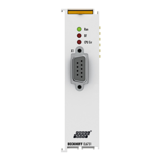
Page 46: Fig. 10 El6731
The 32 bit ADS error code always consists of a general ADS error code (Low Word, see ADS documentation) and a FC310x/EL6731-specific, unique error code (High Word, -> chapter ADS error codes [} 127]). The appropriate text message will also be displayed in the TwinCAT System Manager Logger. - Page 47 0x1000 + station address of the slave IndexGroup 0x100 + slot number (DPV1 parameter) IndexOffset Index (DPV1 parameter) Length Length of the data that is to be written Data In request: data that is to be written EL6731 Version: 2.8...
- Page 48 Feature_Supported (value received from slave) 0x02 - 0x03 Profile_Feature_Supported (value received from slave) 0x04 - 0x05 Profile_Ident_number (value received from slave) MSAC-C2 Abort The MSAC-C2 Abort service allows the C2 connection to the slave to be removed again. Version: 2.8 EL6731...
- Page 49 Length 1538 Data Configuration data of the slave If the IndexGroup indicates that, for Beckhoff devices, tables 0, 1 and 9 are to be read, then the following data is supplied, provided the device is a Beckhoff device: Offset Description...
- Page 50 Bit 27: 1 = ARRAY codes are not supported by PROFIDRIVE slave Bit 28-31: axis number (for single axis modules always 1) IndexOffset Length Parameter length: 1 Data In response: Number of the parameter 's array elements Version: 2.8 EL6731...
- Page 51 FDL interface The FDL interface can be used to send FDL telegrams and pick up received FDL telegrams via ADS [} 42]. This functionality is supported by the FC31xx from V02.66 and the EL6731 from V00.75. FDL send ADS Write can be used to transfer one or several FDL requests or FDL responses. The FDL requests were sent in the specified order, the FDL responses are sent when they are retrieved by another master.
- Page 52 DA.7=1 and SA.7=1: first data byte otherwise if DA.7=1 or SA.7=1 second data byte otherwise third data byte Further indication or confirmation data; if n is even, an Align byte is used for filling; (n+1) is always even perhaps next Cmd: 2=indication follows, 4=confirmation follows Version: 2.8 EL6731...
-
Page 53: Twincat (2.1X) System Manager
Please see further information to TwinCAT 2 and TwinCAT 3 at http://infosys.beckhoff.com. Installation of the TwinCAT real-time driver In order to assign real-time capability to a standard Ethernet port of an IPC controller, the Beckhoff real-time driver has to be installed on this port under Windows. -
Page 54: Fig. 32 System Manager "Options" (Twincat 2)
Alternatively an EtherCAT-device can be inserted first of all as described in chapter Offline configuration creation, section “Creating the EtherCAT device” [} 63] in order to view the compatible ethernet ports via its EtherCAT properties (tab „Adapter“, button „Compatible Devices…“): Version: 2.8 EL6731... -
Page 55: Fig. 35 Ethercat Device Properties(Twincat 2): Click On „Compatible Devices
After the installation the driver appears activated in the Windows overview for the network interface (Windows Start → System Properties → Network) Fig. 36: Windows properties of the network interface A correct setting of the driver could be: EL6731 Version: 2.8... -
Page 56: Fig. 37 Exemplary Correct Driver Setting For The Ethernet Port
Parameterization and commissioning Fig. 37: Exemplary correct driver setting for the Ethernet port Other possible settings have to be avoided: Version: 2.8 EL6731... -
Page 57: Fig. 38 Incorrect Driver Settings For The Ethernet Port
Parameterization and commissioning Fig. 38: Incorrect driver settings for the Ethernet port EL6731 Version: 2.8... -
Page 58: Fig. 39 Tcp/Ip Setting For The Ethernet Port
DHCP. In this way the delay associated with the DHCP client for the Ethernet port assigning itself a default IP address in the absence of a DHCP server is avoided. A suitable address space is 192.168.x.x, for example. Fig. 39: TCP/IP setting for the Ethernet port Version: 2.8 EL6731... -
Page 59: Fig. 40 Identifier Structure
The files are read (once) when a new System Manager window is opened, if they have changed since the last time the System Manager window was opened. A TwinCAT installation includes the set of Beckhoff ESI files that was current at the time when the TwinCAT build was created. -
Page 60: Fig. 41 Onlinedescription Information Window (Twincat 2)
1018 in the configuration. This is also stated by the Beckhoff compatibility rule. Refer in particular to the chapter ‘General notes on the use of Beckhoff EtherCAT IO components’ and for manual configuration to the chapter ‘Offline configuration creation’ [} 63]. - Page 61 Faulty ESI file If an ESI file is faulty and the System Manager is unable to read it, the System Manager brings up an information window. Fig. 45: Information window for faulty ESI file (left: TwinCAT 2; right: TwinCAT 3) EL6731 Version: 2.8...
- Page 62 Parameterization and commissioning Reasons may include: • Structure of the *.xml does not correspond to the associated *.xsd file → check your schematics • Contents cannot be translated into a device description → contact the file manufacturer Version: 2.8 EL6731...
- Page 63 Then assign a real Ethernet port to this virtual device in the runtime system. Fig. 48: Selecting the Ethernet port This query may appear automatically when the EtherCAT device is created, or the assignment can be set/ modified later in the properties dialog; see Fig. “EtherCAT device properties (TwinCAT 2)”. EL6731 Version: 2.8...
- Page 64 (e.g. EK1122 or EK1100), the required port can be selected on the right-hand side (A). Overview of physical layer • “Ethernet”: cable-based 100BASE-TX: EK couplers, EP boxes, devices with RJ45/M8/M12 connector • “E-Bus”: LVDS “terminal bus”, “EJ-module”: EL/ES terminals, various modular modules Version: 2.8 EL6731...
- Page 65 (i.e. highest) revision and therefore the latest state of production is displayed in the selection dialog for Beckhoff devices. To show all device revisions available in the system as ESI descriptions tick the “Show Hidden Devices” check box, see Fig. “Display of previous revisions”.
- Page 66 If current ESI descriptions are available in the TwinCAT system, the last revision offered in the selection dialog matches the Beckhoff state of production. It is recommended to use the last device revision when creating a new configuration, if current Beckhoff devices are used in the real application. Older revisions should only be used if older devices from stock are to be used in the application.
- Page 67 Parameterization and commissioning Fig. 55: EtherCAT terminal in the TwinCAT tree (left: TwinCAT 2; right: TwinCAT 3) EL6731 Version: 2.8...
- Page 68 This scan mode attempts to find not only EtherCAT devices (or Ethernet ports that are usable as such), but also NOVRAM, fieldbus cards, SMB etc. However, not all devices can be found automatically. Fig. 58: Note for automatic device scan (left: TwinCAT 2; right: TwinCAT 3) Version: 2.8 EL6731...
- Page 69 [} 73] with the defined initial configuration.Background: since Beckhoff occasionally increases the revision version of the delivered products for product maintenance reasons, a configuration can be created by such a scan which (with an identical machine construction) is identical according to the device list;...
- Page 70 Likewise, A might create spare parts stores worldwide for the coming series-produced machines with EL2521-0025-1018 terminals. After some time Beckhoff extends the EL2521-0025 by a new feature C. Therefore the FW is changed, outwardly recognizable by a higher FW version and a new revision -1019. Nevertheless the new device naturally supports functions and interfaces of the predecessor version(s);...
- Page 71 Fig. 67: Displaying of “Free Run” and “Config Mode” toggling right below in the status bar Fig. 68: TwinCAT can also be switched to this state by using a button (left: TwinCAT 2; right: TwinCAT 3) The EtherCAT system should then be in a functional cyclic state, as shown in Fig. “Online display example”. EL6731 Version: 2.8...
- Page 72 The connections and devices should be checked in a targeted manner, e.g. via the emergency scan. Then re-run the scan. Fig. 70: Faulty identification In the System Manager such devices may be set up as EK0000 or unknown devices. Operation is not possible or meaningful. Version: 2.8 EL6731...
- Page 73 A ‘ChangeTo’ or ‘Copy’ should only be carried out with care, taking into consideration the Beckhoff IO compatibility rule (see above). The device configuration is then replaced by the revision found; this can affect the supported process data and functions.
- Page 74 If current ESI descriptions are available in the TwinCAT system, the last revision offered in the selection dialog matches the Beckhoff state of production. It is recommended to use the last device revision when creating a new configuration, if current Beckhoff devices are used in the real application. Older revisions should only be used if older devices from stock are to be used in the application.
- Page 75 This function is preferably to be used on AX5000 devices. Change to Alternative Type The TwinCAT System Manager offers a function for the exchange of a device: Change to Alternative Type Fig. 76: TwinCAT 2 Dialog Change to Alternative Type EL6731 Version: 2.8...
- Page 76 To this end the EtherCAT master (Beckhoff TwinCAT) parameterizes each EtherCAT slave during the start-up phase to define which process data (size in bits/bytes, source location, transmission type) it wants to transfer to or from this slave.
- Page 77 EtherCAT and the TwinCAT System Manager offer comprehensive diagnostic elements of this kind. Those diagnostic elements that are helpful to the controlling task for diagnosis that is accurate for the current cycle when in operation (not during commissioning) are discussed below. EL6731 Version: 2.8...
- Page 78 Fig. “Basic EtherCAT Slave Diagnosis in the PLC” shows an example of an implementation of basic EtherCAT Slave Diagnosis. A Beckhoff EL3102 (2-channel analogue input terminal) is used here, as it offers both the communication diagnosis typical of a slave and the functional diagnosis that is specific to a channel.
- Page 79 Parameterization and commissioning Fig. 79: Basic EtherCAT Slave Diagnosis in the PLC The following aspects are covered here: EL6731 Version: 2.8...
- Page 80 The CoE parameter directory (CanOpen-over-EtherCAT) is used to manage the set values for the slave concerned. Changes may, in some circumstances, have to be made here when commissioning a relatively complex EtherCAT Slave. It can be accessed through the TwinCAT System Manager, see Fig. “EL3102, CoE directory”: Version: 2.8 EL6731...
- Page 81 Commissioning interfaces are being introduced as part of an ongoing process for EL/EP EtherCAT devices. These are available in TwinCAT System Managers from TwinCAT 2.11R2 and above. They are integrated into the System Manager through appropriately extended ESI configuration files. EL6731 Version: 2.8...
- Page 82 The target state wanted by the user, and which is brought about automatically at start-up by TwinCAT, can be set in the System Manager. As soon as TwinCAT reaches the status RUN, the TwinCAT EtherCAT Master will approach the target states. Version: 2.8 EL6731...
- Page 83 Fig. 82: Default behaviour of the System Manager In addition, the target state of any particular Slave can be set in the "Advanced Settings" dialogue; the standard setting is again OP. Fig. 83: Default target state in the Slave EL6731 Version: 2.8...
- Page 84 The pre-calculated theoretical maximum E-Bus current is displayed in the TwinCAT System Manager as a column value. A shortfall is marked by a negative total amount and an exclamation mark; a power feed terminal is to be placed before such a position. Version: 2.8 EL6731...
- Page 85 Fig. 86: Warning message for exceeding E-Bus current NOTE Caution! Malfunction possible! The same ground potential must be used for the E-Bus supply of all EtherCAT terminals in a terminal block! EL6731 Version: 2.8...
- Page 86 (in the Features [} 97] tab for the Box). The sequence of the slaves in the PROFIBUS cycle corresponds to the sequence in which they are located in the FC310x/EL6731 device tree. "DP" mode is used for standard DP operation; the operation modes "DP/MC (equidistant)" and "Equidistant (no GC)" are described in section PROFIBUS-MC [} 40].
- Page 87 Shows the current firmware version of the EL6731. Scan Devices... This is used to scan the PROFIBUS. All devices that are found are added to the EL6731. In the case of Beckhoff boxes, the configuration is read precisely. In the case of external devices, the corresponding GSD file will be searched.
- Page 88 GAP update is relevant only for multi-master operation. In single master operation it increases PROFIBUS cycle jitter and is therefore switched off by default. Optimize bus parameters This is used to set the optimized bus parameters. Default bus parameters This is used to set the default bus parameters. Version: 2.8 EL6731...
- Page 89 The DP master changes automatically into the clear mode (the outputs of the slaves are set either to 0 or to the fail-safe value) when it ceases to receive an interrupt from the associated task (e.g. a PLC breakpoint EL6731 Version: 2.8...
- Page 90 DpState [} 121] is not equal 0) (see section Error Reactions [} 115]). Windows watchdog (only FC310x) Not relevant for EL6731. Set WD individually for each slave Here you can select whether the WD should be set individually for each slave (on the Profibus [} 96] tab of the box).
- Page 91 Calculate MC times This button can be used to calculate all DPV2 times automatically. Sync mode Not relevant for EL6731; synchronization is controlled via the distributed clocks and therefore corresponds to the Sync master setting in the FC310x. Activate DRIVECOM server An XML file is generated for the DRIVECOM server (OPC server), through which the SimoCon U tool can access the connected 611U drives via PROFIBUS.
- Page 92 Parameterization and commissioning 5.1.6.2.5 ADS tab The EL6731 is an ADS device with its own net ID, which can be changed here. All ADS services (diagnosis, non-cyclical communication) going to the EL6731 must address this net ID. Fig. 91: ADS tab 5.1.6.2.6 DP Diag tab...
- Page 93 Fig. 93: Box states tab Here, an overview of all current box states, the Repeat counter (increments for each telegram repeat to the slave) and the NoAnswer counter (increments every time the slave fails to answer) is displayed. EL6731 Version: 2.8...
- Page 94 DP slaves in the DP cycle. This part of the DP cycle is referred to as Equi cycle below. If the Equi cycle exceeds the To time of the MC slaves, the last MC slaves at the EL6731 will usually get a synchronization error (error 597 or 598 for Simodrive 611U).
- Page 95 PLL-Overflow/Underflow Counter Not relevant for EL6731. MC Statistics For each MC slave the To-time specifies when, relative to the DP cycle start, the slave should accept the outputs received from the master.
- Page 96 For particularly critical outputs it is possible to set a DP watchdog time down to as little as 2 ms for DP slaves that support a watchdog base time of 1 ms (namely all Beckhoff slaves with the exception of the BK3000 and BK3100, and any devices from other manufacturers whose GSD file contains the entry "WD_Base_1ms_supp = 1").
- Page 97 Parameterization and commissioning DPV1-Class 2 With FC310x/EL6731, a DPV1 class 2 connection to a DPV1 slave can be activated. The Timeout parameter is used to set the connection monitoring time for the class 2 connection (see section DPV1 [} 46]). DP Class 2 If the DP slave is in data exchange with another master but should nevertheless be addressed acyclically by TwinCAT, select "No cycl.
- Page 98 Fig. 97: <Beckhoff> tab Firmware Update This button enables updating of the firmware of a Beckhoff DP slave over a KS2000 cable via the serial port. 2 byte PLC interface Switches on the 2 byte PLC interface of the Beckhoff DP slave.
- Page 99 Online tab (hitherto this only worked with the Simodrive 611U, since a parameter file generated by the SimoCon U is required). In any case it is possible to read and write the parameters via the PKW interface per ADS (see the PKW Protocol [} 49] section). EL6731 Version: 2.8...
- Page 100 Click on a line to change the current value. The description of the respective settings can be found in the documentation of the relevant manufacturer. 5.1.6.3.6 Diag tab Fig. 100: Diag tab The following information can be displayed here: Version: 2.8 EL6731...
-
Page 101: Operation Of Profidrive Mc Drives
Selecting a Profibus fieldbus master card It is assumed that the user is familiar with the procedure for inserting a Profibus device (an EL6731 fieldbus master card/fieldbus master terminal) in the TwinCAT System Manager. Once installation is complete and all bus devices are operational, use Scan Devices in Config mode or the option Insert Device ->... - Page 102 Fig. 101: Inserting an FC31xx PCI I/O device Select the suitable I/O device (in this case Profibus master FC31xx PCI). Operation with a Profibus master EL6731 via EtherCAT is tested with 2 CU. Configuring Profibus DP The Profibus master card is configured via the tab FC31xx. This can only be done during commissioning when the fieldbus is running and operational and all elements are configured: Version: 2.8...
- Page 103 (2) The station address of the fieldbus master is preset to 1. Avoid address conflicts with other devices (e.g. a programming device with the STARTER software) and check the baud rate setting (12 M). (3) The mode must be set to DP/MC (Equidistant). EL6731 Version: 2.8...
- Page 104 MC (DPV2) (with the respective multiple). Please note that numbers 1-8 are available for selection, representing up to 6 drive controllers, a CU and an Active Line Module. In the example (sevenfold) communication via the Profibus takes place in a system of 6 axes and a CU. Version: 2.8 EL6731...
- Page 105 Fig. 104: Inserting a box GSG file Please select "Sinamics S" from the "Select Box" dialog: Ensure that the file Profidrive2.dat and the GSG file (editor) referred to in this file are in directory \TwinCAT \IO\Profibus\ Fig. 105: Selection dialog Example Profidrive2.dat: EL6731 Version: 2.8...
- Page 106 In the Process Data tab the individual drives of the axis (the axis system) are set to telegram 3 by default. Tests indicated that DSC mode (telegram 5) is not necessary in conjunction with TwinCAT. Telegram 390 is assigned to the CU. Version: 2.8 EL6731...
- Page 107 Parameterization and commissioning Fig. 107: Process Data tab, telegram assignment Up to TwinCAT 2.10, B1319, this telegram 370 is not predefined for the Active Line Module ALM, but it can be configured via the Configurable Telegram 0. EL6731 Version: 2.8...
- Page 108 The "Estimated DP Cycle Time" (in this case 374 µs) for all axes must be smaller than the NC task time referred to in section NC Configuration [} 109] (e.g. 2 ms). The actual value should be checked later online. Version: 2.8 EL6731...
- Page 109 1 ms) for the task. The cycle time takes effect if/when auto start is selected. The task cycle time must be greater than the expected fieldbus cycle time (Estimated DP Cycle Time - see section I/O Configuration [} 101]). Shorter times than 2 ms have not yet been tested with Sinamics S120. EL6731 Version: 2.8...
- Page 110 (e.g. mm for a linear axis) in the Settings tab for the respective individual axis. Use the button "Linked with…" to specify which of these logical axes (software structures) are linked to which individual PROFIdrive MC axis (axis system x, #A…#H). Version: 2.8 EL6731...
- Page 111 Cycle Time" for all axes must be smaller than the NC task time referred to above. A safety margin of approx. 10% should prevail. Reading parameters from PROFIdrive MC The following step takes place during commissioning and requires the existence of parameterized axes and a functional fieldbus for the PROFIdrive MC axis system. EL6731 Version: 2.8...
- Page 112 20000H = 2097152DEC INC/rev scaling factor = 360°/rev / (17.08 x 64/50 x 2097152 INC/rev ) = 0.0000078519 mm/INC Setting the encoder parameter scaling factor Enter the determined value [} 111] as the scaling factor for the encoder in the Global tab and accept the values through Download Version: 2.8 EL6731...
- Page 113 Parameterization and commissioning Fig. 113: “Global” tab, scaling factor entry All other axis settings and commissioning steps correspond to the usual procedure. EL6731 Version: 2.8...
-
Page 114: Diagnostics And Error Description
DP master is in CLEAR/OPERATE mode, all DP slaves are in data exchange Flashing DP master is in CLEAR/OPERATE mode, at least one DP slave is in data exchange DP master is in STOP mode CPU Err red EL6731 processor error single flash The EL6731 processor starts Version: 2.8 EL6731... - Page 115 DP cycle (which means that the time at which the following telegram is sent changes), until the DP connection can be established again. Reactions in the master The master's reactions can be set differently for each slave (see the tab for the slave's Features [} 97]). EL6731 Version: 2.8...
- Page 116 Setting the slave's restart behavior if the DP connection to the slave is removed This specifies whether the DP connection to slave whose DP connection has been removed is automatically re-established, or whether this should be done manually as a result of a call to ADS-WriteControl (see ADS- Interface [} 42]). Version: 2.8 EL6731...
- Page 117 Failure of the PLC/IO task (FC310x) or EtherCAT interruption (EL6731) A distinction is made between the cases PLC stop, reaching of a breakpoint and task stop [EL6731: EtherCAT interruption] (IO task, NC task is only stopped on system stop). In the case of a PLC stop, the output data is set to 0 by the PLC, whereas when a breakpoint is reached the data initially remains unchanged.
- Page 118 5.1.8.3 Master Diagnostics Diagnostic Inputs The EL6731 features various diagnostic variables, which describe the state of the terminal and the Profibus and can be linked in the PLC: Fig. 120: Diagnostic inputs for EL6731 in the TwinCAT tree Error Shows the number of slaves with which data exchange could not take place in the last cycle.
- Page 119 0x82 - master not ready for token ring, 0x83 - master ready for token ring, 0x84 - master in token ring). 126 - 127 reserved 128 - 135 State of the EL6731 130 - 131 detected bus errors 136 - 137 Send error counter for all sent telegrams.
- Page 120 DP diagnostic data from the slave. This does not affect the Data-Exchange cycle in the Beckhoff DP master, because the DP diagnostic telegram is sent at the end of the cyclic Data-Exchange cycle, and before the beginning of the next cycle. If the DP diagnostic data read from the slave has changed from its previous state, the DP master sets the "ExtDiagFlag"...
- Page 121 FC310x/EL6731 in slave mode, waiting for data transfer -> slave was parameterized and configured but has not yet received a Data_Exchange telegram FC310x/EL6731 in slave mode, waiting for configuration -> slave was parameterized, but has not yet received a Chk_Cfg telegram FC310x/EL6731 in slave mode, waiting for parameters ->...
- Page 122 1 (i.e. bits 0-3 = 0000B corresponds to a length of one word, while bits 0-3 = 1111B corresponds to a length of 16 words) If the first byte has the type "special identification format", then the second or third bytes have the following meaning: Version: 2.8 EL6731...
- Page 123 A distinction is made in the Extended DiagData between identification diagnosis, channel diagnosis and manufacturer-specific diagnosis. The first byte indicates the type of the diagnosis and the length of the associated data. Several diagnostic types can also follow one another in the Extended DiagData. EL6731 Version: 2.8...
- Page 124 20-126 Manufacturer specific (see the documentation for the DP slave) reserved Module diagnosis The module diagnosis contain one bit for each DP module. The bit indicates whether a diagnosis for the corresponding DP module is present. Version: 2.8 EL6731...
- Page 125 Wire breakage Upper limit value exceeded Value below lower limit Error 10-15 reserved 16-31 Manufacturer specific (see the documentation for the DP slave) Channel type Value Meaning Any type 2 bit 4 bit Byte Word 2 words reserved EL6731 Version: 2.8...
- Page 126 0x05 Access, State Conflict 0x06 Access, Access Denied 0x07 Access, Invalid Range 0x08 Access, Invalid Parameter 0x09 Access, Invalid Type 0x0C 0x00 Resource, Read Constrain Conflict 0x01 Resource, Write Constrain Conflict 0x02 Resource, Busy 0x03 Resource, Unavailable Version: 2.8 EL6731...
- Page 127 5.1.8.9 ADS Error Codes Error code Meaning 0x1129 IndexOffset too large during reading of the FC310x/EL6731 diagnostic data 0x112B IndexOffset too large during reading of the slave diagnostic data 0x112D Invalid station address during reading of the slave diagnostic data...
- Page 128 NR = No response data ready DH = Data High (DP diagnosis pending) RDL = Data not received and Data Low RDH = Data not received and Data High ***) DL and NR are handled by the EL6731 Version: 2.8 EL6731...
-
Page 129: Slave Prioritization/Multiple Dp Cycles
(for TwinCAT 2.8/2.9) of the master to 2. So that the task can send 2 different values to the slave, or is able to receive 2 different values from the slave, the appropriate slave is to be entered into the System Manager EL6731 Version: 2.8... -
Page 130: El6731-0010 - Profibus Slave Terminal
In order to configure the slave for cyclic DP operation, proceed as follows in the TwinCAT system manager: Configure DP slave It is first necessary to configure a "Profibus Slave EL6731, EtherCAT" I/O device (selecting "I/O devices" with the right hand mouse button, and then selecting "Insert device"). The device and a box are added (to this end the GSD file "EL31095F.GSD"... - Page 131 Parameterization and commissioning Find the corresponding channel on the tab "EL6731-0010" of the device ("Search" button), adjust the station address and the baud rate, if necessary (the default setting is 12 Mbaud). Add modules Modules are to be added to the box corresponding to the data that is to be transferred cyclically. This is done by clicking with the right mouse button on the box, and then selecting "Add modules":...
- Page 132 PROFIBUS, with the exception that the requester that initiates the ADS job is always the DP master PC. An EL6731 DP master is then linked to an EL6731-DP slave. In the DP master, the ADS Interface should be activated on the "ADS" tab of the box, and the Net-ID of the DP slave PC is to be entered: Version: 2.8...
- Page 133 At the DP slave the Net-ID of the DP master PC is to be added under Add. NetIds on the device's "ADS" tab: Fig. 128: DP slave, ADS tab: Entering the DP master Net ID with “Add. Net IDs” EL6731 Version: 2.8...
-
Page 134: Ethercat Communication El6731-00X0
The EL6731 can be configured in several ways: 1. Configuration of the EL6731 with StartUp SDOs [} 134]: Here, the StartUp SDOs are calculated in the EtherCAT configurator and transferred to the EtherCAT master, in the same way as is carried out, for example, in the TwinCAT System Manager. - Page 135 EtherCAT communication EL6731-00x0 Fig. 129: Flow chart: Sequence of the configuration of the EL6731 with start SDOs Following a power-on, the EL6731 is in the INIT state and has no DP configuration. The EL6731 is not active on the PROFIBUS. EL6731...
- Page 136 The EL6731 starts communication with the configured DP slaves in the SAFEOP state. Fail Safe data are sent to the DP slaves as long as the EL6731 is in SAFEOP. As soon as the EL6731 has been switched to OP, the data from the EtherCAT outputs are transmitted to the DP slaves.
- Page 137 EtherCAT communication EL6731-00x0 Fig. 130: Flow chart: Sequence of the configuration of the EL6731 with backup parameter storage Following a power-on, the EL6731 is in the INIT state and has no DP configuration. The EL6731 is not active on the PROFIBUS.
-
Page 138: Synchronization
Sync Manager 2 event or, if there is no EtherCAT output process data, via the Sync Manager 3 event. Alternatively, the EL6731 can also be operated in the Distributed Clocks mode, in which case synchronization takes place via the SNYC0 or SYNC1 events. - Page 139 EtherCAT communication EL6731-00x0 configured DP slaves have been dealt with, the EtherCAT input data is updated and the DP cycle is finished. If the next SM2 (SM3) event is received before the DP cycle is completed, the Cycle Exceed counter (0x1C32:0B or 0x1C33:0B) is incremented and one DP cycle is skipped.
- Page 140 EtherCAT communication EL6731-00x0 Fig. 133: Transfer of output data with LWR, input data with LRD telegram (Separate Input Update = TRUE, Task Cycle Time = Base Time) Transmission of the output data with LWR telegram and the input data with LRD telegram (Separate...
- Page 141 EtherCAT communication EL6731-00x0 SYNC1-synchronous The DP cycle is started through the SYNC0 event. Before the first telegram is sent, the system waits for the SYNC1 event, so that the global control telegram is sent with a maximum jitter of 500 ns. The remainder of the DP cycle sequence corresponds to that in the case of synchronization without Distributed Clocks.
-
Page 142: Object Description And Parameterization
EtherCAT XML Device Description The display matches that of the CoE objects from the EtherCAT XML Device Description. We rec- ommend downloading the latest XML file from the download area of the Beckhoff website and in- stalling it according to installation instructions. - Page 143 Storage contains the complete StartUp SDOs (see Con- figuration of the EL6731 with Backup Parameter Storage [} 136]). The EL6731 is rebooted 5s after the flashing of the Backup Parameter Storage (switches to INIT with AL status code = 0x60). The data have the following mean-...
- Page 144 EtherCAT communication EL6731-00x0 Index 10F3 Diagnosis History Index (hex) Name Meaning Data type Flags Default 10F3:0 Diagnosis History Maximum subindex UINT8 0x45 (69 10F3:01 Maximum Messages Maximum number of stored messages UINT8 0x00 (0 A maximum of 50 messages can be stored...
- Page 145 EtherCAT communication EL6731-00x0 Index 1880 DPM TxPDO-Par Status PDO Index (hex) Name Meaning Data type Flags Default 1880:0 DPM TxPDO-Par Sta- PDO parameter TxPDO 129 UINT8 0x06 (6 tus PDO 1880:06 Exclude TxPDOs Specifies the TxPDOs (index of TxPDO mapping objects)
- Page 146 EtherCAT communication EL6731-00x0 Index 1887 DPM TxPDO-Par DC Cyclic Statistics Index (hex) Name Meaning Data type Flags Default 1887:0 DPM TxPDO-Par DC PDO parameter TxPDO 136 UINT8 0x06 (6 Cyclic Statistics 1887:06 Exclude TxPDOs Specifies the TxPDOs (index of TxPDO mapping objects)
- Page 147 EtherCAT communication EL6731-00x0 Index 1A82 DPM TxPDO-Map PDO Toggle Index (hex) Name Meaning Data type Flags Default 1A82:0 DPM TxPDO-Map For each configured DP slave there is a bit in this PDO UINT8 PDO Toggle that toggles every time new DP input data has been re- ceived from the DP slave and updated in the EtherCAT input data.
- Page 148 EtherCAT communication EL6731-00x0 Index 1A86 DPM TxPDO-Map Cycle Statistics Index (hex) Name Meaning Data type Flags Default 1A86:0 DPM TxPDO-Map Cy- PDO Mapping TxPDO 135 contains the DP master cycle UINT8 0x05 (5 cle Statistics statistics (object 0xF10F [} 157]) for the SM synchronous...
- Page 149 EtherCAT communication EL6731-00x0 Index 1C12 RxPDO assign Index (hex) Name Meaning Data type Flags Default 1C12:0 RxPDO assign PDO Assign Outputs: the RxPDOs must be assigned in UINT8 0x00 (0 the order of their indexes. The RxPDOs of the configured DP slaves (0x1600 [} 144]-0x167E) must be assigned if...
- Page 150 SYNC shift time for the EtherCAT master outputs. When setting DC SYNC1-syn- chronous, this time may also to be considered for the SYNC1 shift time of the EL6731. If the ShiftTooShort counter (0x1C32:0D) increments, then the corresponding shift time is set too low.
- Page 151 SAFEOP to OP. If it increments, then the SYNC shift time for outputs in the case of the EtherCAT master (DC SYNC0) or the SYNC1 shift time in the case of the EL6731 (DC SYNC1) is too short. 1C32:0F Minimum Cycle Dis-...
- Page 152 EtherCAT communication EL6731-00x0 Index 1C33 SM input parameter Index (hex) Name Meaning Data type Flags Default 1C33:0 SM input parameter Synchronization parameters for the inputs UINT8 0x20 (32 1C33:01 Sync mode Current synchronization mode: UINT16 0x0022 (34 • 0: Free Run •...
- Page 153 EtherCAT communication EL6731-00x0 6.1.3.2 Profile-specific objects (0x6000-0xFFFF) The profile-specific objects have the same meaning for all EtherCAT slaves that support the profile 5001. Index 6000-67C0 DP Inputs Slave yyy Index (hex) Name Meaning Data type Flags Default 6000+n*16: DP Inputs Slave yyy...
- Page 154 EtherCAT communication EL6731-00x0 Index 8000-87C0 DP Slave Parameter Set Slave yyy Index (hex) Name Meaning Data type Flags Default 8000+n*16: DP Slave Parameter This object contains the DP configuration of the (n+1) UINT8 0x33 (51 Set Slave yyy configured DP slave (0 <= n <125). The object is to be...
- Page 155 EtherCAT communication EL6731-00x0 Index 8000-87C0 DP Slave Parameter Set Slave yyy Index (hex) Name Meaning Data type Flags Default (8000+n*16) Master reaction after no response BIT1 0x00 (0 DP fault Data exchange with all DP slaves is stopped (Set_Prm-Unlock to all slaves); DP communica-...
- Page 156 EtherCAT communication EL6731-00x0 Index F008 Code word Index (hex) Name Meaning Data type Flags Default F008:0 Code word reserved UINT32 0x00000000 Index F010 Module list Index (hex) Name Meaning Data type Flags Default F010:0 Module list Max. subindex UINT8 0x00 (0...
- Page 157 EtherCAT communication EL6731-00x0 Index F102 DP Slave Status data Index Name Meaning Data type Flags Default F102:0 DP Slave Status data This object contains the status of communication to the UINT8 DP slaves that is mapped to TxPDO 133 (index 0x1A84 [} 147])
- Page 158 EtherCAT communication EL6731-00x0 Index F800 DP Bus Parameter Set Index (hex) Name Meaning Data type Flags Default F800:0 DP Bus Parameter This object contains the DP bus parameters. The object UINT8 0x18 (24 is to be transmitted with Complete Access, or SubIndex 0...
- Page 159 EtherCAT communication EL6731-00x0 Index F920 AoE Settings Index (hex) Name Meaning Data type Flags Default F920:0 AoE Settings Max. subindex UINT8 0x01 (1 F920:01 Local AoE Net ID Local AoE Net ID OCTET- STRING[6] * These parameters depend on the baud rate; the following table shows the default values for the respective...
-
Page 160: Profibus Slave
TwinCAT System Manager. 2. Configuration of the EL6731-0010 with Backup Parameter Storage [} 162]: Here, the configuration of the CANopen slave is stored in the flash memory of the EL6731-0010 and need only be transmitted once. - Page 161 EtherCAT communication EL6731-00x0 Fig. 136: Flow chart: Sequence of the configuration of the EL6731-0010 with start SDOs Following a power-on, the EL6731-0010 is in the INIT state and has no DP configuration. The EL6731-0010 is not active on the PROFIBUS. DP slave configuration The DP configuration is carried out via SDO download in the PREOP state.
- Page 162 The DP function of the EL6731-0010 is active in the SAFEOP state. As long as the EL6731-0010 is in SAFEOP, the DP input data that are sent to the DP-master are set to 0. As soon as the EL6731-0010 has been switched to OP, the data from the EtherCAT outputs are transmitted to the DP master.
- Page 163 INIT to PREOP. Since the StartUp SDOs from the Configuration of the EL6731-0010 with StartUp SDOs [} 160] are stored in the Backup Parameter Storage object, the sequence is the same as the one described there. Hence, the stored data is initially written to object 0x8000 and the EL6731-0010 is active on the EL6731...
-
Page 164: Object Description And Parameterization
EtherCAT XML Device Description The display matches that of the CoE objects from the EtherCAT XML Device Description. We rec- ommend downloading the latest XML file from the download area of the Beckhoff website and in- stalling it according to installation instructions. - Page 165 EtherCAT communication EL6731-00x0 Index 100A Software version Index (hex) Name Meaning Data type Flags Default 100A:0 Software version Firmware version of the EtherCAT slave STRING Index 1011 Restore default parameters Index (hex) Name Meaning Data type Flags Default 1011:0 Restore default pa-...
- Page 166 Storage contains the complete StartUp SDOs (see Con- figuration of the EL6731-0010 with Backup Parameter Storage). The EL6731-0010 is rebooted 5s after the flashing of the Backup Parameter Storage (switches to INIT with AL status code = 0x60). The data have the fol-...
- Page 167 EtherCAT communication EL6731-00x0 Index 1A00 DPS TxPDO-Map Slave Index (hex) Name Meaning Data type Flags Default 1A00:0 DPS TxPDO-Map This TxPDO contains the DP output data of the DP slave UINT8 Slave that were received by the DP master. There is an entry in the TxPDO mapping object 0x1A00 for each DP module with DP output data configured in object 0x8002 [} 170].
- Page 168 EtherCAT communication EL6731-00x0 Index 1C32 SM output parameter Index (hex) Name Meaning Data type Flags Default 1C32:0 SM output parameter Synchronization parameters for the outputs UINT8 0x20 (32 1C32:01 Sync mode Current synchronization mode: UINT16 0x0000 (0 • 0: Free Run...
- Page 169 EtherCAT communication EL6731-00x0 6.2.2.2 Profile-specific objects (0x6000-0xFFFF) The profile-specific objects have the same meaning for all EtherCAT slaves that support the profile 5001. Index 6000 Input Data Index (hex) Name Meaning Data type Flags Default 6000:0 Input Data This object contains the DP output data of the DP slave UINT8 (data are received by the DP master ).
- Page 170 EtherCAT communication EL6731-00x0 Index 8000 DP Slave Parameter Set Slave Index (hex) Name Meaning Data type Flags Default 8000:0 DP Slave Parameter This object contains the DP configuration of the (n+1) UINT8 0x33 (51 Set Slave yyy configured DP slave (0 <= n <125). The object is to be...
- Page 171 EtherCAT communication EL6731-00x0 Index F000 Modular device profile Index (hex) Name Meaning Data type Flags Default F000:0 Modular device profile General information for the modular device profile UINT8 0x02 (2 F000:01 Module index dis- Index distance of the objects of the individual channels...
-
Page 172: Appendix
Note • It is recommended to use the newest possible firmware for the respective hardware • Beckhoff is not under any obligation to provide customers with free firmware updates for delivered products. NOTE Risk of damage to the device! Pay attention to the instructions for firmware updates on the separate page [} 173]. -
Page 173: Firmware Update El/Es/Em/Elm/Epxxxx
Check on the Beckhoff web page whether more up-to-date documentation is available. Firmware Update EL/ES/EM/ELM/EPxxxx This section describes the device update for Beckhoff EtherCAT slaves from the EL/ES, ELM, EM, EK and EP series. A firmware update should only be carried out after consultation with Beckhoff support. -
Page 174: Device Description Esi File/Xml
Update of XML/ESI description The device revision is closely linked to the firmware and hardware used. Incompatible combinations lead to malfunctions or even final shutdown of the device. Corresponding updates should only be carried out in consultation with Beckhoff support. Version: 2.8 EL6731... - Page 175 Fig. 139: Scan the subordinate field by right-clicking on the EtherCAT device If the found field matches the configured field, the display shows Fig. 140: Configuration is identical otherwise a change dialog appears for entering the actual data in the configuration. Fig. 141: Change dialog EL6731 Version: 2.8...
- Page 176 Most EtherCAT devices read a modified ESI description immediately or after startup from the INIT. Some communication settings such as distributed clocks are only read during power-on. The Ether- CAT slave therefore has to be switched off briefly in order for the change to take effect. Version: 2.8 EL6731...
-
Page 177: Firmware Explanation
• offline: The EtherCAT Slave Information ESI/XML may contain the default content of the CoE. This CoE directory can only be displayed if it is included in the ESI (e.g. "Beckhoff EL5xxx.xml"). The Advanced button must be used for switching between the two views. -
Page 178: Updating Controller Firmware *.Efw
Switch to the Online tab to update the controller firmware of a slave, see Fig. Firmware Update. Fig. 145: Firmware Update Proceed as follows, unless instructed otherwise by Beckhoff support. Valid for TwinCAT 2 and 3 as EtherCAT master. • Switch TwinCAT system to ConfigMode/FreeRun with cycle time >= 1 ms (default in ConfigMode is 4 ms). -
Page 179: Fpga Firmware *.Rbf
The TwinCAT System Manager indicates the FPGA firmware version. Click on the Ethernet card of your EtherCAT strand (Device 2 in the example) and select the Online tab. The Reg:0002 column indicates the firmware version of the individual EtherCAT devices in hexadecimal and decimal representation. EL6731 Version: 2.8... - Page 180 Fig. 147: Context menu Properties The Advanced Settings dialog appears where the columns to be displayed can be selected. Under Diagnosis/Online View select the '0002 ETxxxx Build' check box in order to activate the FPGA firmware version display. Version: 2.8 EL6731...
- Page 181 Older firmware versions can only be updated by the manufacturer! Updating an EtherCAT device The following sequence order have to be met if no other specifications are given (e.g. by the Beckhoff support): • Switch TwinCAT system to ConfigMode/FreeRun with cycle time >= 1 ms (default in ConfigMode is 4 ms).
- Page 182 • In the TwinCAT System Manager select the terminal for which the FPGA firmware is to be updated (in the example: Terminal 5: EL5001) and click the Advanced Settings button in the EtherCAT tab: • The Advanced Settings dialog appears. Under ESC Access/E²PROM/FPGA click on Write FPGA button: Version: 2.8 EL6731...
-
Page 183: Simultaneous Updating Of Several Ethercat Devices
The firmware and ESI descriptions of several devices can be updated simultaneously, provided the devices have the same firmware file/ESI. Fig. 149: Multiple selection and firmware update Select the required slaves and carry out the firmware update in BOOTSTRAP mode as described above. EL6731 Version: 2.8... -
Page 184: Support And Service
Beckhoff's branch offices and representatives Please contact your Beckhoff branch office or representative for local support and service on Beckhoff products! The addresses of Beckhoff's branch offices and representatives round the world can be found on her internet pages: http://www.beckhoff.com You will also find further documentation for Beckhoff components there. - Page 185 Fig. 9 BIC as data matrix code (DMC, code scheme ECC200)............. Fig. 10 EL6731 ............................Fig. 11 Spring contacts of the Beckhoff I/O components................. Fig. 12 Recommended distances for standard installation position ............Fig. 13 Other installation positions ......................Fig. 14 Correct positioning........................
- Page 186 Example of commissioning aid for a EL3204 ................Fig. 82 Default behaviour of the System Manager .................. Fig. 83 Default target state in the Slave ....................Fig. 84 PLC function blocks ........................Fig. 85 Illegally exceeding the E-Bus current ..................Version: 2.8 EL6731...
- Page 187 Fig. 128 DP slave, ADS tab: Entering the DP master Net ID with “Add. Net IDs” ........133 Fig. 129 Flow chart: Sequence of the configuration of the EL6731 with start SDOs ......... 135 Fig. 130 Flow chart: Sequence of the configuration of the EL6731 with backup parameter storage..137 EL6731 Version: 2.8...
- Page 188 Fig. 136 Flow chart: Sequence of the configuration of the EL6731-0010 with start SDOs......161 Fig. 137 Flow chart: Sequence of the configuration of the EL6731-0010 with backup parameter storage 163 Fig. 138 Device identifier consisting of name EL3204-0000 and revision -0016 ........174 Fig.
Need help?
Do you have a question about the EL6731 and is the answer not in the manual?
Questions and answers