Table of Contents
Advertisement
Quick Links
Advertisement
Table of Contents

Related Manuals for Brainchild PR10

Summary of Contents for Brainchild PR10
- Page 1 Paperless Recorder PR10/PR20/PR30 User Manual UMFPR01G March 2019...
- Page 2 Safety This recorder is compliant with the requirements of EN61010-1, UL 61010C-1 & CSA C22.2 No. 24-93. If the equipment is used in a manner not specified by the manufacturer, the protection provided by the equipment may be impaired. Manufacturer is not liable for any damages incurred to equipment/personal during installation or use of equipment as explained in this document.
- Page 3 The documentation and the software included with this product are copyrighted 2016 by Brainchild Electronic Co. Ltd. All rights are reserved. Brainchild Electronic Co., Ltd. reserves the right to make improvements in the products described in this manual at any time without notice.
-
Page 4: Table Of Contents
PR20 ................................... 36 2.2.1.3 PR30 ................................... 38 2.2.2 Portable styles ..............................39 2.2.2.1 Bottom Side View of PR20 & PR10 ..........................40 2.2.2.2 Front Side View of PR20 & PR10 ..........................40 2.2.2.3 Bottom Side View of PR30 ............................41 2.2.2.4 Front Side View of PR30 ............................. - Page 5 2.3.1 Analog Input Card (AI206 & AI203) ........................42 2.3.2 Relay Output card (RO206) ..........................43 2.3.3 Digital Input card (DI206) ............................ 44 2.3.4 Combination Digital Input and Output card (RD233) ..................44 2.3.5 Analog output cards (AO206) ..........................45 2.3.6 PID Process Control Module (PC201) ........................
- Page 6 5.1.1.4 Filter .................................... 78 5.1.1.5 Log ....................................80 5.1.1.6 Sensor ..................................81 5.1.1.7 Offset ................................... 82 5.1.1.8 Gain ..................................... 82 5.1.1.9 Modbus ..................................82 5.1.1.10 Events ..................................82 5.1.2 Digital Input ................................. 84 5.1.2.2 Desc .................................... 85 5.1.2.3 Type .................................... 85 5.1.2.4 Events ..................................
- Page 7 5.2.4.19 Output Power Limit..............................149 5.2.4.20 Digital Filter ................................149 5.2.4.21 Auto-Tuning and Manual Tuning ..........................150 5.2.5 Profile ................................152 5.2.5.1 Ramp & Dwell ................................153 5.2.5.2 Name ..................................154 5.2.5.3 Segments .................................. 154 5.2.5.4 Jobs ................................... 157 5.2.5.5 Start/Stop Profile (Ramp &Dwell) ..........................
- Page 8 ................................171 TART 5.6.1 Start .................................. 171 5.6.2 Stop .................................. 171 ................................... 172 IMER 5.7.1 Type .................................. 172 5.7.1.1 Countdown ................................173 5.7.1.2 Repeat Countdown ..............................173 5.7.1.3 Daily ..................................173 5.7.1.4 Weekly ..................................173 5.7.1.5 Monthly ..................................173 5.7.2 Action ................................
- Page 9 5.13.5 Report Data ..............................198 5.13.6 Output Files ..............................198 5.13.7 USB Printer Configuration ........................... 198 5.13.8 Network Printer Configuration ........................198 5.13.9 Sample Configuration of Printer ........................199 5.14 .............................. 202 YSTEM NFORMATION 5.14.1 Firmware Upgrade ............................202 5.14.2 Touch Screen Calibration ..........................
- Page 10 6.3.5.1 File .................................... 296 6.3.5.2 Edit .................................... 299 6.3.5.3 Format ..................................299 6.3.5.4 View ..................................302 6.3.5.5 Objects ..................................303 6.3.5.6 Project ..................................304 6.3.6 Standard bar ..............................304 6.3.7 Format bar ................................ 305 6.3.8 Project Explorer ..............................306 6.3.8.1 Screen ..................................
- Page 11 8.4.4.3 Transformation as Math Channel ..........................476 8.4.5 AO Conversion Example ..........................476 8.4.6 External Channel Conversion for AI channel ....................477 8.4.7 External Channel Conversion for DI and DO channel ..................477 8.4.8 External Channel Conversion for AO channel ....................478 8.4.9 External Channel Conversion for Math channel ....................
-
Page 12: Introduction
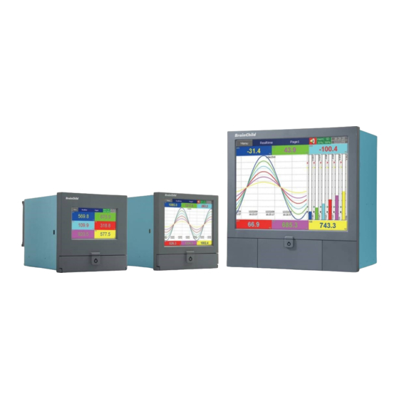
❖ Available in three display sizes 4.3”, 5.6〞and 12.1” ❖ PR10, with a 4.3” display, with 3 or 6 universal analog inputs and 24 Optional External Channels ❖ PR20, with a 5.6” display, with 6, 12, 18 or 24 universal analog inputs and 48 Optional External Channels ❖... -
Page 13: Pc Software
1.2.3 PC Software The PR series has the below user-friendly software for configuration, analysis, data acquisition and custom display 1. Free Basic Software Historical Viewer for configuration and analysis 2. Extensive Software Data Acquisition Studio for configuration, analysis and data acquisition on PC. - Page 14 1-1 Historical Viewer Software 1-2 Configuration Viewer Software in Historical Viewer Software Page 14 of 479...
- Page 15 1-3 Real Time Viewer in Data Acquisition Studio Software 1-4 Panel Studio Software for Custom Display Page 15 of 479...
-
Page 16: Comparison Of Pr Series Recorders
1-1 Comparison of PR10, PR20 and PR30 1.4 Expandable Input and Output cards There are 4 rear expansion slots in PR10 and PR20 and 16 rear expansion slots in PR30 available for expansion with the following plug and play I/O Cards. -
Page 17: Analog Input Cards (Part Number Ai206 & Ai203)
1.4.1 Analog Input cards (part number AI206 & AI203) These two cards are used for 3 or 6-channel analog inputs. Each input is isolated from each other to avoid noise and to ensure stable measurement. 1.4.2 Relay Output card (RO206) Each card includes 6 relay outputs. -
Page 18: Analog Output Cards (Ao206)
1.4.5 Analog Output cards (AO206) Each card includes 6 channels. They are used for 4-20mA, 0-20mA current output, 0-5V, 1-5V, 0-10VDC voltage output. 1.4.6 PID Process Control card (PC201) Each card includes one single loop PID process control function with ramp and soak profile segment. -
Page 19: Smart Mechanism
No of days = (The capacity of SD card memory x Log Speed) / (2 x # of hours per day x 60 x 60 x Number of channels) If the user is using USB to dump the data then it is necessary to insert USB memory back to recorder after loading recorded data onto PC. -
Page 20: Ordering Code
1.8 Ordering Code 1.8.1 PR10 Ordering code PR1003 (3 Analog Inputs) Other Inputs and Outputs 0: none 6: 3 relays + 3 DI PR1006 (6 Analog Inputs) Other Inputs and Outputs 0: none 1: 6 relays 3: 6DI 6: 3 relays + 3 DI... -
Page 21: Pr20 Ordering Code
1.8.2 PR20 Ordering code PR2003 (3 Analog Inputs) Other Inputs and Outputs 0: none 6: 3 relays + 3 DI C: 3 relays + 3 DI + 6 AO PR2006 (6 Analog Inputs) Other Inputs and Outputs 0: none 1: 6 Relays 3: 6 DI 5: 6 AO Special options... - Page 22 Mounting types, Power Cord & Switch 0: panel mount, no power cord, no power switch 1: panel mount, no power cord, power switch 2: portable, UL & CSA power cord, power switch 3: portable, VDE power cord, power switch 4: portable, SAA power cord, power switch 5: portable, BS power cord, power switch 6: portable, no power cord, power switch 7: Panel mount, UL &...
-
Page 23: Pr30 Ordering Code
1.8.3 PR30 Ordering code PR3006 (6 Analog Inputs) - PR3012 (12 Analog Inputs) PR3018 (18 Analog Inputs) PR3024 (24 Analog Inputs) PR3030 (30 Analog Inputs) PR3036 (36 Analog Inputs) PR3042 (42 Analog Inputs) PR3030 (48 Analog Inputs) Relay 0: none 1: 6 Relays 2: 12 Relays 3: 18 Relays... -
Page 24: Pid Process Control Card Pc201 Ordering Code
IF232A RS-232 communication module for PR30 IF485A RS-422/485 communication module for PR30 90-250VAC 47-63Hz panel mount power supply board without power Switch for PR10 PM201 and PR20 90-250VAC 47-63Hz panel mount power supply board with power switch For PR10 PM202... -
Page 25: Specifications
90-250VAC 47-63Hz portable power supply board with power switch for PR10 and PM203 PR20 PM211 11-36VDC panel mount power supply board without power switch for PR10 and PR20 PM212 11-36VDC panel mount power supply board with power switch for PR10 and PR20 PM213... -
Page 26: Analog Input Specifications (Ai203 & Ai206)
PR10 PR20 PR30 SD Card Slot Standard one slot at Front USB Slot Standard one USB slot in front and one USB slot in the rear Pulse Input Optional DI card support pulse Input up to 100Hz PID Process Control PID, Ramp &... - Page 27 Input Characteristics: Type Range Accuracy at 25 ˚C Input Impedance -120 ~ 1000 ˚C (-184 ~ 1832 ˚F) ±1 ˚C 3.12MΩ -200 ~ 1370 ˚C (-328 ~ 2498 ˚F) ±1 ˚C 3.12MΩ -250 ~ 400˚C (-418 ~ 752˚F) ±1 ˚C 3.12MΩ...
- Page 28 Type Range Accuracy at 25 ˚C Input Impedance PT1000 (α = 0.00385) -200 ~ 350 ˚C (-328 ~ 662 ˚F) ±0.4 ˚C 2.0KΩ PT50 (α = 0.00391) -200 ~ 850 ˚C (-328 ~ 1562 ˚F) ±0.4 ˚C 2.0KΩ PT100 (α = 0.00391) -200 ~ 850 ˚C (-328 ~ 1562 ˚F) ±0.4 ˚C 2.0KΩ...
-
Page 29: Digital Input Specifications (Di206 & Rd233)
1.9.3 Digital Input Specifications (DI206 & RD233) Channels: DI206: 6 Channels per card, RD233: 3 Channels per card Logic Low: -5V minimum, 0.8V maximum Logic High: 3.5V minimum, 24V maximum External pull-down Resistance: 1KΩ maximum External pull-up Resistance: 1.5MΩ minimum 1.9.4 Relay Output Specifications (RO206 &... -
Page 30: Input2
Sensor Break Responding Time: ❖ Within 4 seconds for TC, RTD and mV inputs ❖ 0.1 second for 4-20 mA and 1 - 5 V inputs Input 1 Characteristics: Type Range Accuracy @ 25°C Input Impedance -120°C to 1000°C (-184°F to 1832°F) ±2°C 2.2 MΩ... -
Page 31: Output1/Output2
1.9.6.4 Output1/Output2 1. Relay Rating: 2A/240 VAC, life cycles 200,000 for Resistive load 2. Pulsed Voltage: Source Voltage 5V, current limiting resistance 66Ω 3. Linear Output: Resolution: 15 bits Output Regulation: 0.01 % for full load change Output Settling Time: 0.1 sec. (stable to 99.9 %) Isolation Breakdown Voltage: 1000 VAC Temperature Effect: ±0.0025 % of SPAN /°C Linear Output Characteristics:... -
Page 32: Profiler
ON-OFF: 0.1 - 100.0(°F) hysteresis control (P band = 0) P or PD: 0 - 100.0 % offset adjustment PID: Fuzzy logic modified Proportional band 0.1 ~ 900.0°F, Integral time: 0 - 1000 Seconds, Derivative time 0 - 360.0 seconds Cycle Time: 0.1 - 100.0 seconds Manual Control: Heat (MV1) and Cool (MV2) Auto-tuning: (MV2) Cold start and warm start... -
Page 33: Real Time Clock Accuracy Vs Temperature Inside Of The Housing
Vibration Resistance: 10-55 Hz, 10m/ s² for 2 hours Shock Resistance: 30m/ s² (3g) for operation, 20g for transportation Operation Position: no inclined restriction Dimensions: Panel Mount style: PR10/PR20:144(W) x 144(H) x 193mm (D) PR30:288(W) x 288(H) x 194mm (D) Standard Panel Cut-out: PR10/PR20:137 x 137mm PR30:281 x 281mm 1.9.11 Approval Standards... -
Page 34: Unpacking
Operating Temperature 0°C to 50 °C Humidity 20% to 90% RH(Non-condensing) Altitude 2000 M Maximum Pollution Degree Level II IEC1010-1(EN61010-1) Power 90 ~ 250 VAC, 50/60 Hz or 11-36VDC 2.2 Dimensions 2.2.1 Panel mounting style 2.2.1.1 PR10 Page 34 of 479... - Page 35 2-1 PR10 Front Side 2-2 PR10 Right Side Page 35 of 479...
-
Page 36: Pr20
2-3 PR10 Panel Cut-out Dimensions 2.2.1.2 PR20 2-4 PR20 Front Side Page 36 of 479... - Page 37 2-5 PR20 Right Side 2-6 PR20 Panel Cut-out Dimensions Page 37 of 479...
-
Page 38: Pr30
2.2.1.3 PR30 2-7 PR30 Front Side 2-8 PR30 Right Side Page 38 of 479... -
Page 39: Portable Styles
2-9 PR30 Cut-out Dimensions Note: ❖ Do not over tighten mounting clamp screws that could result in distortion of the case. ❖ There is no mounting angle restriction. ❖ The mounting torque used for 4 sides of the housing should be 2.0 KgF-cm and not more than 2.5 KgF-cm 2.2.2 Portable styles Page 39 of 479... -
Page 40: Bottom Side View Of Pr20 & Pr10
2.2.2.1 Bottom Side View of PR20 & PR10 2-10 PR10 & PR20 Portable Type Bottom Side View 2.2.2.2 Front Side View of PR20 & PR10 2-11 PR10 & PR20 Portable Type Front Side View Page 40 of 479... -
Page 41: Bottom Side View Of Pr30
2.2.2.3 Bottom Side View of PR30 2-12 PR30 Portable Type Bottom Side View 2.2.2.4 Front Side View of PR30 2-13 PR30 Portable Type Front Side View Page 41 of 479... -
Page 42: Bottom Stand Clips
2.2.2.5 Bottom Stand Clips 2-14 Portable Type Bottom Stand Clips 2.2.2.6 Top Holding Handle 2-15 Portable Type Top Holding Handle 2.3 Input and Output Configuration The Input and Output cards needs to be inserted to the rear slots or removed from the rear slots at the Power OFF condition. -
Page 43: Relay Output Card (Ro206)
2.3.2 Relay Output card (RO206) The relay output card RO206 includes 6 relays rated 5 Amp/240 VAC each. Plug the card into a rear slot and power on the recorder. The recorder will automatically detect the card and display the output type and its location in a specific slot in System Info mode while doing the configuration. -
Page 44: Digital Input Card (Di206)
2.3.3 Digital Input card (DI206) This card includes 6 channels of event inputs. As above, plug the card into rear slot and power on the recorder. The recorder will automatically detect it, and then display the input type and its location in a specific slot in System Information mode while doing the configuration. -
Page 45: Analog Output Cards (Ao206)
2.3.5 Analog output cards (AO206) These cards are 6-channel analog output cards. They are used to retransmit process values to other devices like meters, controllers, etc. The configuration Menu can be reached by pressing Menu and then pressing more and then pressing Config key. It will display a tree type configuration layout for easy user configuration. -
Page 46: Wiring
Note: ❖ The IO Modules should not be removed or Inserted to the device when the Power is ON. This should be carried out in the Power OFF Condition only. ❖ For removing the IO Modules, First remove the metal screws then remove the plastic screws, after that press the lock on the top and bottom of the Card and pull to remove it. -
Page 47: Analog Input Wiring
2.4.2 Analog Input Wiring 2.4.2.1 AI206 wiring 2.4.2.2 AI203 Wiring Page 47 of 479... -
Page 48: Relay Output Wiring
2.4.3 Relay Output Wiring 2.4.3.1 RO206 Page 48 of 479... -
Page 49: Digital Input Wiring
2.4.4 Digital Input Wiring 2.4.4.1 DI206 Page 49 of 479... -
Page 50: Combination Relay Output And Digital Input Wiring
2.4.5 Combination Relay Output and Digital Input Wiring 2.4.5.1 RD233 2.4.6 Analog Output Wiring 2.4.6.1 AO206 Page 50 of 479... -
Page 51: Pid Process Control Card Wiring
2.4.7 PID Process Control Card Wiring 2.4.7.1 PC201 2.4.8 RS-232, RS-422, and RS-485 wiring 2.4.8.1 RS232 Wiring Page 51 of 479... -
Page 52: Rs422 Wiring
2.4.8.2 RS422 Wiring RS232 to RS422 Converter 2.4.8.3 RS485 Wiring RS232 to RS485 Converter External Memory Card There are two types of external storage for the User to use in the recorder. One is the SD card and other is USB memory. There are two slots for inserting USB memory, one in the front and other on the rear side of the recorder. - Page 53 Note The maximum capacity of external memory supported by recorder is 32GB. The external memory must be ❖ formatted to FAT or FAT32. To read measured data and events on USB memory and SD card Memory, it is necessary to install either the ❖...
-
Page 54: Basic Functions Of Recorders
3. BASIC FUNCTIONS OF RECORDERS 3.1 Configuration The configuration of the recorder follows a tree type layout. This makes it easy for the users to go through the different sub menus easily and do not miss any configuration. 3.2 Firmware The PR series recorder has 4 different versions of firmware for the user to select as per the application requirement. -
Page 55: Pulse Input Through Digital Input
3.3 Pulse input through Digital input The recorder will support pulse input up to 100Hz via digital input. The digital input can be configured as pulse counter to count the no of pulses. 3.4 PID control with Ramp & Soak Profile function The recorder has the option to use PID control function by using PC201 PID process control card. -
Page 56: Handwriting Messages On Historical Trend Screens
3.9 Handwriting Messages on Historical Trend Screens Handwriting Messages on Historical trend screen is a useful feature for the user to highlight important events. The User can write handwritten messages using a stylus on Historical Trend screens. This is shown in the below picture. 3.10 Custom Display Screen In plus 2 and plus 3 versions of firmware the recorder allows the user to download the custom screens linked with Analog and Digital Tags from the custom display editor software Panel Studio. -
Page 57: System Clock Synchronization Via Internet
Besides on-board AI and DI inputs, the recorder can accept inputs through Modbus communication. The PR10, PR20, and PR30 can have a maximum of up to 24, 48 and 96 channels respectively. The detailed configuration and related information are available in... -
Page 58: Multilingual Languages
3.19 Multilingual Languages The recorder provides multiple language options for the user to select as per their convenience. The available languages are Brazil Portuguese, Chinese (Simplified, Traditional), Czech, Danish, Dutch, English, French, German, Greek, Italian, Japanese, Korean, Polish, Portuguese, Russian, Spanish, Swedish, Thai, Turkish. -
Page 59: Getting Started
4. GETTING STARTED The recorder has a TFT touch screen display capable of complex graphical representation, internal memory and SD card slot or USB drive slot for data storage. The unit is easily programmable, and the average user will probably never need to use most of the features or functions available in the recorder. This chapter will give the user a brief system overview and guide the first-time user in a simplified setup which will enable you to begin recording with the least amount of effort. - Page 60 4.1.1.1.1 Real Time Real time menu will allow the user to access the real time display of the configured display pages, Overview display, PID Control card display page and custom screen display page. 4.1.1.1.2 Mode Mode Menu will allow the user change the graphical display mode. The available display modes are Trend, Bar Graph, Digital, Mix Mode, Individual Mode and Circular Mode (only for PR30).
- Page 61 4.1.1.1.3 Alarm Alarm menu will allow the user to access the real time alarm page. In this page the user can view the real time alarms and acknowledge the alarms. Page 61 of 479...
- Page 62 The user can acknowledge the alarm by pressing the ACK key. The user can navigate the alarm display by using the scroll keys . The user can go back to Home screen by pressing the Home key. The user can access other menus by pressing the menu key.
- Page 63 user go back to the home screen by pressing the Home key. The up down scroll keys are used to scroll down the pages in individual tabs. The user can access other menus by pressing the menu key. 4.1.1.1.5 History History menu will allow the user to access the historical data of the display pages.
- Page 64 The historical display page will allow the user to navigate the historical data and do the handwritten remarks on the display page. The user can do the navigation on the screen using the four scroll keys . The user can increase or decrease the zoom rate by using the two softkyes .
- Page 65 and external memory by using the softykey . The user go back to the home screen by pressing the Home key. The user can access other menus by pressing the menu key. 4.1.1.1.5.1 Handwriting Messages on Historical Trend Screens Handwriting Messages on Historical trend screen is a useful feature for the user to highlight important events.
- Page 66 If the User wants to change colour of the pen, he/she can change it by using the key to change the color of the pen. If the User wants to erase part of a message, he/she can do this by using the key to erase part of the message.
- Page 67 If the user wants to undo part of a message, he/she can do this by using the key undo the last part of the message. If the User wants to delete the written message, he/she can this do by using the key delete the written message.
- Page 68 If the user wants to save the written message, he/she can do this by using the key save the written message. By using the key, the user can exit the page without saving the data. Note: The handwriting messages are saved once can’t modified or deleted. Page 68 of 479...
- Page 69 4.1.1.1.6 Event Event menu will allow the user to access the historical events and reports. By using the Event and Report tabs the event list and report list can be viewed in the respective page. The selected tab can be changed by using the left and right scroll keys .The user go back to the home screen by pressing the Home...
- Page 70 The Report list can be navigated up and down by using keys. The report of previous and next day,week, month depends on the selection of mode can be navigated by using keys. The mode can be switched between List, Daily, Weekly,Monthly by using key.
- Page 71 4.1.1.1.7.1 Dump Dump the historical data from internal memory to external memory such as SD Card or USB Disk. The user can select the data to be dumped to external memory. The recorder will allow the user to select the period to be dumped after pressing the key.
- Page 72 Dump Option-Batch Mode Dump Option- Normal Mode 4.1.1.1.7.2 Clear Clear all the historical data and event list stored in the memory. The user can select the data to be cleared. The recorder will allow the user to select the period to be cleared after pressing the key.
- Page 73 Clear Option- Normal Mode Clear Option-Batch Mode 4.1.1.1.7.3 Operate Manually operate the jobs from the available jobs directly without any events. The details of all the jobs are explained in section 5.3. Page 73 of 479...
- Page 74 4.1.1.1.7.4 Config This will allow the user to access the configuration page. The configuration page configuration is explained in Chapter 5. 4.1.1.1.7.5 Stop Stop the batch and logging. The Title bar will show pause when the logging is stopped. Logging Paused 4.1.1.1.7.6 Logout Logout the user.
- Page 75 The comments can be navigated by using keys. The Batch name and lot no can’t be edited during the batch is running. 4.1.1.1.7.8 Shutdown Shutdown the recorder. Page 75 of 479...
-
Page 76: Configuration
5. CONFIGURATION This section will explains about the procedure to configure the recorder. Press (Menu), then More and then Config soft key to enter Configuration mode. A tree type layout appears with a provision to configure Channel, Tools, Message, Display, Instrument, Security, Auto-Output, Demo, and system Information. -
Page 77: Channel
Various options are available to enter into configuration page menus. Option-1: Select the required menu by using up & down directional keys, then press “Enter” key Option-2: Select the required menu directly with a touch, then press “Enter” key Option-3: Select the required menu by pressing the menu two times quickly, it is same as a double click from a mouse There are four soft key are available to save, load, to load the default settings and move to home screen. -
Page 78: Desc
Copy: copy the channel configuration from one channel to another channel. Paste: Paste the copied configuration to the channel. Press Copy key in the source channel and press paste key in the destination channel. 5.1.1.1.1 Name Enables the User to define the name for each channel with a maximum of 18 characters. Select “Name”, then Press “Enter”, soft key, a keyboard with several keys will appear. - Page 79 5.1.1.4.2 Difference This will log the data only there is at least a difference between the current data and the last logged data for a period. The difference will be defined by allowance and the period is defined by holding time.
-
Page 80: Log
5.1.1.5 Log 5.1.1.5.1 Data Type The data type for logging is 2 byte. 2 byte range: -32767 to +32767 5.1.1.5.2 Trigger Two options are available for the user to select. 1. Disable: Select disable while the recording of a specific channel is not required at this time 2. -
Page 81: Sensor
5.1.1.6 Sensor 5.1.1.6.1 Type Select the input type of the sensor for the channel. 5.1.1.6.2 Unit The engineering unit of input. 5.1.1.6.3 Range Select the range for the input based on Sensor type Page 81 of 479... -
Page 82: Offset
5.1.1.6.4 Scale Appears only for linear input type. The user can scale the input to the engineering unit as per the application requirement. 5.1.1.7 Offset It is to offset the input value to correct the sensor error. 5.1.1.8 Gain It is a multiplier to correct the sensor error. The correct value = (the process value x gain) + offset 5.1.1.9 Modbus The scaling of the channel value in Modbus communication. - Page 83 For example, Set point =10 At 10.00.01 Hrs, Tag1=40 At 10.00.02 Hrs, Tag1 = 51 Then, job or alarm is activated 5.1.1.10.1.6 Dev- It is deviation- event. This event will be triggered on the negative deviation of process value. The job or alarm is activated when the process value is deviated by the value lower than set point from the previous process value.
-
Page 84: Digital Input
5.1.1.10.4 Job1 & Job2 The job is called as a task to be performed when the event is activated. There are two jobs Job1 and Job2 can be added to perform in any event. A typical example is to trigger an alarm buzzer in the event of a high temperature. Each channel can accept five different types of events (or alarms) and each event can create two jobs. -
Page 85: Desc
Copy: copy the channel configuration from one channel to another channel. Paste: Paste the copied configuration to the channel. Press Copy key in the source channel and press paste key in the destination channel. 5.1.2.1.1 Name Enables the User to define the name for each channel with a maximum of 18 characters. Select “Name”, then Press “Enter”, soft key, a keyboard with several keys will appear. -
Page 86: Events
5.1.2.4 Events A maximum of 2 events are supported for every digital Input channel. A maximum of two jobs can be configured for each event. *Note: Events will not appear if Logic Level selected as Pulse Counter Press “Add” to add new event and Press “Remove” to remove selected event 5.1.2.4.1 Type Select the event type Low L or High H 5.1.2.4.1.1 Holding time... - Page 87 Note: Number of digital inputs shown one the DI screen depends on number of Digital input cards inserted in the paperless recorder. Example: After pressing a “Start” switch, latch ON Digital Ouput1, after pressing a “Pause” switch, latch Off Digital Output1. Start Timer, Stop Timer, Reset Totalizer, Reset Counter, Reset MaxMinAve values of all the channels etc...
-
Page 88: Math Channel
The Math channel is used to do the mathematical operations. The Math channel can be configured as Math or counter or Totalizer. The maximum no of math channel in different PR recorders as below. PR Recorder PR10 PR20 PR30 Maximum Math Channels After entering the Configuration menu, in the Channel, select Math then Press the “Enter”... -
Page 89: Desc
Copy: copy the channel configuration from one channel to another channel. Paste: Paste the copied configuration to the channel. Press Copy key in the source channel and press paste key in the destination channel. 5.1.3.1.1 Name Enables the User to define the name for each channel with a maximum of 18 characters. Select “Name”, then Press “Enter”, soft key, a keyboard with several keys will appear. -
Page 90: Log
5.1.3.3.2 Math Configure the channel as Math channel. 5.1.3.4 Log 5.1.3.4.1 Data Type The data type for logging is 2 byte or 4 byte 2 byte range: -32767 to +32767 4 byte range:-3.4E+38 to +3.4E +38 Page 90 of 479... -
Page 91: Expression
5.1.3.4.2 Trigger Two options are available for the user to select. 3. Disable: Select disable while the recording of a specific channel is not required at this time 4. Enable: Select enable while the recording of a specific channel is required at this time 5.1.3.4.3 Method This is the method of logging measured data. - Page 92 The Source consists of all available Analog inputs, Digital Inputs, Math inputs, external channels. The Operator consists of available mathematical expressions. Use Source, Operator and keyboard to define the Math equation. 5.1.3.5.1 Available Math Expressions The available math expression for the user to configure the math expressions are as below. Expressions Mathematics Functions Addition...
-
Page 93: Scale
Expressions Mathematics Functions ATG(x) Remainder of x/y 5.1.3.6 Scale The scale is used to do scale the math channel value. 5.1.3.6.1 Unit The user can define engineering unit for the channel as per the application requirement. 5.1.3.6.2 Transformation This is mainly used to scale the non-linear process input value. The available options for the user in transformation menu are disable, value and math channel. - Page 94 Press “Add” soft key to add a new row into the Transformation table Delete Press “Delete” soft key to delete existing row from the Transformation table Copy Press to copy existing row in the Transformation table to create a duplicate entry Mode Press to toggle between Input and Output entries in the Transformation table Up &...
- Page 95 5.1.3.6.3.1 Counter The counter is used to configure the counter. 5.1.3.6.3.1.1 Unit Defines the unit of counter 5.1.3.6.3.1.2 Preset Defines the pre-set value for the counter. 5.1.3.6.4 Totalizer Configure the channel as totalizer 5.1.3.6.4.1 Input Input type for the Totalizer. Select Analog Input or DI Pulse counter. 5.1.3.6.4.2 Source Select the source for the Totalizer from Analog input/Math/Counter/Totalizer/DI Pulse counter...
-
Page 96: Modbus
5.1.3.6.4.4 Decimal Defines the decimal point for the Totalizer 5.1.3.6.4.5 Period Select the period for the totalizer. The available options are Seconds, Minutes, Hours and Days 5.1.3.6.4.6 Unit Defines the unit of totalizer 5.1.3.6.4.7 Preset Defines the pre-set value for the Totalizer. 5.1.3.6.4.8 Low Cut Defines the Low Cut value for the Totalizer. - Page 97 5.1.3.8.1.2 L It is low event. When the process value is lower than low limit, then the alarm or job associated with this event is actuated. 5.1.3.8.1.3 HH It is high high event. When the process value is higher than high high limit, then the alarm or job associated with this event is actuated.
-
Page 98: Examples For Math Channel Application
5.1.3.8.3.3 Log Event Log as event 5.1.3.8.4 Job1 & Job2 The job is called as a task to be performed when the event is activated. There are two jobs Job1 and Job2 can be added to perform in any event. A typical example is to trigger an alarm buzzer in the event of a high temperature. - Page 99 The below steps are required to follow. 1. Configure the AI Channel as per the input configuration. 2. Configure one math channel with the required conversion using transformation table. 3. Configure the Expression with the input channel 4. Add the Transformation table type as values 5.
- Page 100 5.1.3.9.3 Relative Humidity Application The relative humidity can be calculated using Math Channel application. For this we need two analog inputs with RTD input to measure dry bulb temperature and wet bulb temperature. For this example the recorder has two analog inputs with RTD input in AI1 to measure dry bulb temperature and AI2 to measure wet bulb temperature.
- Page 101 3 Math channels are required to calculate one RH. Td = AI1, analog input for dry bulb temperature (PT100) Tw =AI2, analog input for wet bulb temperature (PT100) Math1 = Ed = 6.112*EXP((17.502*AI1)/(240.97+AI1)) Math2 = Ew= 6.112*EXP((17.502*AI2)/(240.97+AI2)) Math3=RH= (Math2-(0.66875*(1+0.00115*AI2)*(AI1-AI2))/Math1)*100 Page 101 of 479...
- Page 102 Now Math3 will display Relative humidity in % Math channels are virtual channels. They contain measured values based on equations. These values can be recorded similar to physically connected Analog inputs and display as digital values, trends, bar graphs etc. 5.1.3.9.4 Counter Example The user requires the number of occurrences of an event in a day.
- Page 103 The counter value will be logged in the report and reset to start the count of next day. The Historical report can be viewed in Event mode Report tab with the selection of Daily mode. 5.1.3.9.5 Totalizer Example Water flow rate is in M /Sec.
-
Page 104: Analog Output
The Totalizer value will be logged in the report and reset to start the totalizer of next day. The Historical report can be viewed in Event mode Report tab with the selection of Daily mode. The Weekly and monthly report can also be viewed by changing the mode. 5.1.4 Analog Output The Analog Output card dip switches needs to be set for required output type. - Page 105 After entering the Configuration menu, in the Channel, select AO then Press the “Enter” soft key to get into AO Channel configuration menu. . It displays the AO channel AO1 as the first AO channel configuration page. Press directional navigation keys at the bottom to select other channels.
-
Page 106: Desc
5.1.4.1 Desc The description about a specific channel on the recorder. 5.1.4.2 Type The type of analog output channel. The analog output channel can be configured as Voltage or Current. The output menu will differ depends on the selection of Type. 5.1.4.3 Output Select the required output. -
Page 107: Modbus
Expressions Mathematics Functions SIN(x) sin(x) COS(x) cos(x) EXP(x) SQRT(x) Square root of x LN(x) LOG(x) ABS(x) Absolute of x POW (x,y) ROUND(x) The closest integral number to x HI(x,y) The bigger value between x and y INV(x) TG(x) tan(x) CTG(x) 1/tan(x) ASIN(x) ACOS(x) -
Page 108: Desc
External channels. The no of available External channels will be varied depends on the recorder model. The available External channel on the different recorder models as below. PR Recorder PR10 PR20 PR30 No of External Channels After entering the Configuration menu, in the Channel, select External then Press the “Enter”... -
Page 109: Name
the column. After completing Configuration, press soft key, then press soft key to return to main display. All configurations will be saved automatically. Copy: copy the channel configuration from one channel to another channel. Paste: Paste the copied configuration to the channel. Press Copy key in the source channel and press paste key in the destination channel. -
Page 110: Modbus Register Value Conversion
5.1.6.4.3 Method This is the method of logging measured data. Select the column Method and press Enter. Then choose the required Log method from the available methods Instant, Average, Minimum or Maximum of data. 5.1.6.4.3.1 Instant Logging the last measured data at the logging interval 5.1.6.4.3.2 Average Logging the averaged of sampled measured data at the logging interval 5.1.6.4.3.3 Minimum... -
Page 111: Modbus
5.1.6.6 Modbus The scaling of the channel value in Modbus communication. 5.1.6.7 Events Events are frequently used for Alarm purposes. The events can be used to operate digital outputs (DO), Timer, Totalizer, Counter or Report. There are maximum five events can be added to each analog input. -
Page 112: Controller
5.2 Controller This will allow the user to configure the PID process control card. The maximum no of PID Process control cards will vary depends on the recorder model as described below PR Recorder PR10 PR20 PR30 No of PID Process... -
Page 113: Name
After entering the Configuration menu, in the Channel, select Controller then Press the “Enter” soft key to get into Controller Channel configuration menu. It displays the Controller channel C1 as the first Controller channel configuration page. Press directional navigation keys at the bottom to select other channels. -
Page 114: Parameter Configuration
5.2.2.1 Parameter Configuration The below table will explains the available parameters and their functions. Parameter Parameter Range Range Default Unit*E Notation Description Low*B High*B Value*C 100.0°C Set point 1 SP1L SP1H (212.0°F) TIME Dwell Time 6553.5 Minute 100.0°C A1SP Alarm 1 Set point (212.0°F) -200.0°C 200.0°C... - Page 115 Parameter Parameter Range Range Default Unit*E Notation Description Low*B High*B Value*C OFST Offset Value for P control 100.0 25.0 Reference Constant for Specific REFC Function -200.0°C 200.0°C SHIF PV1 Shift (offset) Value (-360.0°F) (360.0°F) 500.0°C 10.0°C Proportional Band 1 Value (900.0°F) (18.0°F) Integral Time 1 Value...
- Page 116 Parameter Parameter Range Range Default Unit*E Notation Description Low*B High*B Value*C 1000.0°C SP1H -19999 45536 SP1 High Scale Value (1832.0°F) IN2 Signal Type Selection 0*B13 20*B15 IN2U IN2 Unit Selection 0*B13 2*B13 IN2 Decimal Point Selection 0*B14 3*B14 IN2L -19999 45536 IN2 Low Scale Value IN2H...
- Page 117 Parameter Parameter Range Range Default Unit*E Notation Description Low*B High*B Value*C Cold Junction Low Temperature CJTL -5.0°C 40.0°C °C Calibration Coefficient Cold Junction Gain -199.9 199.9 Calibration Coefficient Reference Voltage1 REF1 -199.9 199.9 Calibration Coefficient for RTD1 Serial Resistance 1 Calibration -199.9 199.9 Coefficient for RTD1...
- Page 118 Parameter Parameter Range Range Default Unit*E Notation Description Low*B High*B Value*C Point 7 Indication Value of Special IND7 -19999 45536 Sensor Point 8 Signal Value of SIG8 -19999 45536 Special Sensor Point 8 Indication Value of Special IND8 -19999 45536 Sensor Point 9 Signal Value of SIG9...
- Page 119 Parameter Parameter Range Range Default Unit*E Notation Description Low*B High*B Value*C Contains Lockout Status code MODE *B36 *B34 and Current system mode CMND Command Password 65535 Job Password 65535 Cold Junction Compensation CJCT -40.0°C 90.0°C °C Temperature Current Process Rate -16383 16383 PV/min...
- Page 120 If PVMD= Range of SP2 same as range of P1-2,P2-1 IN1,IN2 5-4 Range of SP2 *B3: Display Symbol and Description of FUNC Parameter Value Display Symbol Description BASC Basic Function Mode FULL Full Function Mode 5-5 Mode Selection *B4: Display Symbol and Description for COMM Parameter Value Display Symbol Description...
- Page 121 Parameter Value Display Symbol Description 8BIT 8 Data Bits 5-9 Communication Data Length *B9: Display Symbol and Description for PARI Parameter Value Display Symbol Description EVEN Even Parity Odd Parity NONE No Parity 5-10 Communication Parity *B10: Display Symbol and Description for STOP Parameter Value Display Symbol Description...
- Page 122 5-14 Display Unit for IN1 & IN2 *B14: Display Symbol and Description for DP1 &DP2 Parameter Value Display Symbol Description NO-DP No Decimal Digit 1-DP One Decimal Digit 2-DP Two Decimal Digits 3-DP Three Decimal Digits 5-15 Decimal Digit for DP1 & DP2 *B15: Display Symbol and Description for IN2 Parameter Value Display Symbol...
- Page 123 *B19: Failure transfer mode for output 1 and output 2, select BPLS ( Bumpless transfer ) or 0.0 ~ 100.0 % to continue output 1 and output 2 control function as the unit fails , power starts or manual mode starts. *B20: Display Symbol and Description for OUT2 Parameter Value Display Symbol...
- Page 124 Parameter Value Display Symbol Description NONE Sleep Mode Function disabled Sleep Mode Function Enabled 5-26 Sleep Mode *B27: Display Symbol and Description for PVMD Parameter Value Display Symbol Description Use PV1 as Process Value Use PV2 as Process Value P1-2 Use PV1-PV2 Difference as Process Value P2-1 Use PV2-PV1 Difference as Process Value...
- Page 125 Parameter Value Display Symbol Description Parameter TI1 put ahead Parameter TD1 put ahead C.PB Parameter CPB put ahead Parameter DB put ahead Parameter SP2 put ahead Parameter PB2 put ahead Parameter TI2 put ahead Parameter TD2 put ahead 5-30 SEL Selection *B32: Display Symbol and Description for FILE Parameter Value Display Symbol...
- Page 126 *B34: Error Messages Error Display Error Description Corrective Action Code Symbol Illegal setup values used: PV1 is used for Check and correct setup values of PVMD and Er 01 both PVMD and SPMD that is SPMD, PV and SV can't use the same value for meaningless for control.
- Page 127 Error Display Error Description Corrective Action Code Symbol Check and correct setup values of OUT2 and Illegal setup values used: OUT2 select Er 06 A2FN. OUT2 will not perform alarm function if =AL2 but A2FN select NONE A2FN select NONE. Illegal setup values used: Dwell timer Check and correct setup values of A1FN and Er 07...
- Page 128 Error Display Error Description Corrective Action Code Symbol Memory comparison error, different 1. Check and correct the wiring and grounding CAPE value detected in the EEPROM and problems to minimize the system noise. mapped RAM 2. Return to factory for repair. EEPE EEPROM can't be written correctly Return to factory for repair.
- Page 129 Parameter Specified product Value 11.XX Reserved 12.XX Reserved 13.XX Reserved 14.XX ST-20A smart transmitter ( software setup) 15.XX ST-20A smart transmitter ( DIP switches setup ) 5-33 PROG Code *B36: Display Symbol and Description of MODE Parameter Value Description Perform normal mode Enter calibration mode Enter auto-tuning mode Enter failure mode...
-
Page 130: Channel
If AOFN= Same Unit as Unit of P1-2,P2-1 PV1,PV2 MV1,MV2 5-38 Unit Determination of AOLO & AOHI *E5: Unit is the same as unit of PV1 (IN1) *E6: Unit is the same as unit of PV2 (IN2) 5.2.2.1.1 Default This will allows the user to load the default values of the Process Control Card Parameters 5.2.3 Channel The Channel will allow the user to configure the channels to be logged in the recorder from PID process control card. -
Page 131: Name
There are five channels available for every PID Process control card for logging. They are listed as below. 1. C1_PV – Process Value 2. C1_SV- Set Value 3. C1_ALM - Alarm 4. C1_EROR - Error 5. C1_ProfileERROR – Profile Error Similar to C1 PID Process control card C2, C3, C4, C5, C6, C7, C8 PID process control card parameters also available depends on the recorder model no and their connection on the recorder 5.2.3.1 Name... -
Page 132: Modbus
This is the method of logging measured data. Select the column Method and press Enter. Then choose the required Log method from the available methods Instant, Average, Minimum or Maximum of data. 5.2.3.5.3.1 Instant Logging the last measured data at the logging interval 5.2.3.5.3.2 Average Logging the averaged of sampled measured data at the logging interval 5.2.3.5.3.3 Minimum... - Page 133 It is high event. When the process value is higher than high limit, then the alarm or job associated with this event is actuated. 5.2.3.7.1.2 L It is low event. When the process value is lower than low limit, then the alarm or job associated with this event is actuated.
-
Page 134: Configuration Of Process Control Card
PV stays at above that SP more than the holding time and then only activate the action for that event. The range of holding time can be set from 1 min to 60 min. 5.2.3.7.3 Log The event can be logged as alarm or event. They can be selected from the available options. They are as below. -
Page 135: Cool Only On-Off Control
0 is used to adjust the control offset (manual reset). Adjust CYC1 according to the output 1 type (O1TY). Generally, CYC1= 0.5 ~ 2 sec for SSRD and SSR, CYC1=10 ~ 20 sec for relay output .CYC1 is ignored if linear output is selected for O1TY. - Page 136 Note The ON-OFF control may result excessive overshoot and undershoot problems in the process. The P (or PD) control will result in a deviation process value from the set point. It is recommended to use PID control for the Heat-Cool control to produce a stable and zero offset process value. Other Setup Required O1TY, CYC1, O2TY, CYC2, A2SP, A2DV, O1TY &...
-
Page 137: Heater Break Alarm
36.0% to 36.0 % of PB1 (or PB2 if PB2 is selected). A negative DB value shows an overlap area over which both outputs are active. A positive DB value shows a dead band area over which neither output is active 5.2.4.4 Heater Break Alarm A current transformer CT94-1 should be installed to detect the heater current if a heater break alarm is required. -
Page 138: Failure Transfer
5.2.4.7 Failure Transfer The controller will enter failure mode as one of the following conditions occurs. 1 SB1E Error occurs ( due to the input 1 sensor break or input 1 current below 1mA, if 4- 20mA is selected or input 1 voltage below 0.25V if 1-5 V is selected ), if PV1, P1-2 or P2-1 is selected for PVMD or PV1 is selected for SPMD. -
Page 139: Pv1 Shift
2 The controller enters the failure mode. 3 The controller enters the manual mode. 4 The controller enters the calibration mode. As the Bumpless transfer is activated, the controller will transfer to open-loop control and uses the previous averaging value of MV1 and MV2 to continue control. 5.2.4.8.1 Without Bumpless Transfer Since the hardware and software need time to be initialized, the control is abnormal as the power is recovered and results in a large disturbance to the process. -
Page 140: Sp1 Range
5.2.4.10 SP1 Range SP1L (SP1 low limit value) and SP1H (SP1 high limit value) in setup menu are used to confine the adjustment range of SP1. Example: A freezer is working in its normal temperature range -10°C to -15°C. In order to avoid an abnormal set point, SP1L and SP1H are set with the following values: SP1L = -15°C SP1H = -10°C Now SP1 can only be adjusted within the range from -10 C to -15 C. -
Page 141: Process Alarms
5.2.4.12 Process Alarms A process alarm sets an absolute trigger level (or temperature). When the process (could be PV1, PV 2 or PV1-PV2) exceeds that absolute trigger level an alarm occurs. A process alarm is independent from set point. Adjust A1FN (Alarm 1 function) in setup menu. One of 8 functions can be selected for process alarm. - Page 142 5-2 Latching Process Alarm 5-3 Holding Process Alarms 5-4 Latching/Holding Process Alarm Although the above descriptions are based on alarm 1, the same conditions can be applied to alarm 2. 5.2.4.12.2 Alarm Types 5.2.4.12.2.1 Deviation Alarm A deviation alarm alerts the user when the process deviates too far from set point. The user can enter a positive or negative deviation value (A1DV, A2DV) for alarm 1 and alarm 2.
- Page 143 (A1HY or A2HY) can be selected to avoid interference problem of alarm in a noisy environment. Normally, A1HY and A2HY can be set with a minimum (0.1) value. Trigger levels of alarm are moving with set point. For alarm 1, Trigger levels=SP1+A1DV 1/2 A1HY. For alarm 2, Trigger levels=SP1+A2DV 1/2 A2HY.
- Page 144 5-8 Latching/Holding Deviation Alarm 5.2.4.12.2.2 Deviation Band Alarm A deviation band alarm pre-sets two reference levels relative to set point. Two types of deviation band alarm can be configured for alarm 1 and alarm 2. These are deviation band high alarm (A1FN or A2FN select DB.HI) and deviation band low alarm (A1FN or A2FN select DB.LO).
-
Page 145: Event Input
5-11 Holding Deviation Band Alarm 5-12 .Latching/Holding Deviation Band Alarm 5.2.4.13 Event Input The Event input accepts a digital type signal. Three types of signals can be connected to event input. These are Relay or switch contacts Open collector pull low TTL logic level. One of ten available functions can be chosen by using (EIFN) contained in setup menu. -
Page 146: Second Set Point
10 D.O1.2: Disable both Output 1 and Output 2 by clearing MV1 and MV2 values as soon as the event input is activated. Note: When any of D.O1, D.O2 or D.O1.2 is selected for EIFN, the output 1 and/or output 2 will revert to their normal conditions as soon as the event input is released. 11 LOCK: All parameters are locked to prevent from being changed. -
Page 147: Ramp &Dwell
5.2.4.16 Ramp & Dwell 5.2.4.16.1.1 Ramp The ramping function is performed during power up as well as any time the set point is changed. Choose MINR or HRR for SPMD, the unit will perform the ramping function. The ramp rate is programmed by using RAMP which is available in user configuration of Process Control Card Example without Dwell Timer Select MINR for SPMD, IN1U selects °C, DP1 selects 1-DP, Set RAMP=10.0. -
Page 148: Remote Set Point
Select HRR for SPMD, IN1U selects PU, DP1 select 2-DP, Set RAMP=60.00 A2FN selects TIMR, Set TIME=20.0 as power is applied the process value starts from 0.00 and set SP1=30.00, SP2=40.00. The timer output is used to control event input. 5.2.4.17 Remote Set Point SPMD selecting PV1 or PV2 will enable the Process Control Card to accept a remote set point signal. -
Page 149: Output Power Limit
PVMD=P1-2 or P2-1 SPMD=SP1.2 The response of PV2 will be parallel to PV1 as shown in the following diagram The PV display will indicate PV1-PV2 value if P1-2 is chosen for PVMD or PV2-PV1 value if P2- 1 is chosen for PVMD. If the user needs PV1 or PV2 to be displayed instead of PV, they can use the Display Mode to select PV1 or PV2 to be viewed. -
Page 150: Auto-Tuning And Manual Tuning
filter with time constant specified by FILT parameter which is contained in setup menu. The default value of FILT is 0.5 sec. before shipping. Adjust FILT to change the time constant from 0 to 60 seconds. 0 second represents no filter is applied to the input signal. The filter is characterized by the following diagram. Note The Filter is available only for PV1, and is performed for the displayed value only. - Page 151 Page 151 of 479...
-
Page 152: Profile
5.2.5 Profile This will allow the user to configure the ramp and soak profiles for PID process control card. The recorder can be configured with maximum of 50 profiles with each 32 segments limited to 1000 segments in total. After entering the Configuration menu, select Profile then Press the “Enter” soft key to get into Profile configuration menu. -
Page 153: Ramp & Dwell
5.2.5.1 Ramp & Dwell Many applications need to vary temperature or process value with time. Such applications need a controller which varies a set point as a function of time. This Process Control Process Control Card can do this. The set point is varied by using a set point profiler. The profile is stored as a series of “ramp” and “dwell “segments, as shown below. -
Page 154: Name
The below four kinds of combination are allowable for connecting segments. Ramp-Ramp Ramp-Dwell Dwell-Ramp Dwell-Dwell 5.2.5.2 Name Enable the user to define the name for each Profile with the maximum limit of 18 Characters. Select “Name”, then Press “Enter”, soft key, a keyboard with several keys appears. Press “Shift” to select special characters. - Page 155 Duration Duration of the segment for the Ramp can be set in Hour: Minute: Second. The PID Values to be used for this RAMP is PID1 or PID2. Hold Back As the set point ramps up or down (or dwells), the measured value may lag behind or deviate from the set point by an undesirable amount.
- Page 156 5-14 Holdback on Positive Ramp 5-15 Holdback on Negative Ramp 5.2.5.3.1.2 Dwell Segment Parameters Duration Duration of the segment for the Dwell can be set in Hour: Minute: Second. The PID Values to be used for this Dwell is PID1 or PID2. 5.2.5.3.1.3 Go Back Segment Parameters This segment will jump to the specified in the segment mentioned on the Segment for the no of cycles mentioned in Cycle.
-
Page 157: Jobs
5.2.5.3.1.4 End Segment Parameters This is an End segment of the profile to End the profile with set point mentioned in Set Point with the PID values in the selection of PID1 or PID2 as per the selection. 5.2.5.3.1.5 Time to Target Segment Parameters This is similar to ramp segment with automatic calculation of ramp rate by the Process Control Card with the reference of Set point and duration given by the user. -
Page 158: Start/Stop Profile (Ramp &Dwell)
5.2.5.5 Start/Stop Profile (Ramp &Dwell) The Profile can be start, Hold or stop from the Real time display page of process control module. The Profile can be selected and run from the Run button on the display page. Press Run and select the profile to be run then press ok to start the Profile. -
Page 159: Oven Control With Zone Temperature Recording Application
5.2.5.6 Oven Control with Zone Temperature Recording Application An Oven is designed to dry the products with 6 zones. The Zone Temperature is controlled by a single temperature controller. The temperatures of the different zones are recorded to ensure the operation of different zones. -
Page 160: Jobs
5.3 Jobs There are various types of jobs available in the recorder to activate by an event. The available jobs are listed as below. 5.3.1 No Action Do nothing 5.3.2 Send Email Send Email directly from Recorder 5.3.3 Pause Stop logging data. 5.3.4 Start Start logging data. -
Page 161: Enable Timer
5.3.10 Enable Timer Start the timer, and then select Target timers 5.3.11 Disable Timer Stop the timer, and then select Target from Timers 5.3.12 Preset Totalizer Set a pre-set value to the target Totalizer. 5.3.13 Reset Totalizer Reset Totalizer to zero. Select a single Target Totalizer or All totalizers 5.3.14 Enable Totalizer Starts the Totalizer. -
Page 162: Print Snapshot
5.4 Display This will allow the user to configure the real time display pages on the recorder. The maximum no of display pages and pens per display page will vary depends on the recorder model no. PR10 PR20 PR30 Display pages Pens/Page After entering the Configuration menu, select “Display”... -
Page 163: Name
Copy: copy the configuration from one page to another page. Paste: Paste the copied configuration to the page. Press Copy key in the source page and press paste key in the destination page. 5.4.1 Name Enables the User to define the name for each page with a maximum of 18 characters. Select “Name”, then Press “Enter”, soft key, a keyboard with several keys will appear. -
Page 164: Direction
16. 2 hour/page (Circular Mode only) 17. 4 hour/page (Circular Mode only) 18. 8 hour/page (Circular Mode only) 19. 12 hour/page (Circular Mode only) 20. 1 day/page (Circular Mode only) 21. 2 day/page (Circular Mode only) 22. 1 week/page (Circular Mode only) 23. -
Page 165: Pen
5-17 Circular Scale 5.4.8 Pen This will configure the display pens of that display page and their properties. 5.4.8.1 Channel Selects a specific channel for that pen from analog input, Math, Counter, Totalizer, External Channels. Select disable if a specific pen is not required to display any channels. 5.4.8.2 Color Selects the colour for that pen. -
Page 166: Trend Graph Scale Position
Totalizer, Counter and AO, the user may enable these items in the status bar. The Status bar is displayed at Lower part of the display page. One status bar can be configured for each page. Each status bar consists of 6 tags in PR10 and PR20 and 10 tags in PR30 for the user configuration. Note Status bar configuration is not shared in all the pages. - Page 167 Page 167 of 479...
-
Page 168: Batch
5.5 Batch This will allow the user to configure the batch configuration. This menu will be visible to the user when batch is enable in instrument menu configuration. After entering the Configuration menu, select “Batch” then Press the “Enter” key to get into Batch configuration menu. It displays the Display page Page1 as the first display page configuration page. -
Page 169: Example For Batch Application
5.5.3 Example for Batch Application The operator wants to start a batch every day at 8.00am and stop the batch at 12.00am. Configuration Timer1 Type: Daily Action: Enable Time – Hour: 8 Min: 0 Sec: 1 Job1: Start Job2: No Action Timer2 Type: Daily Action: Enable... -
Page 170: How To Dump Batch Data To External Usb Memory
5.5.5 How to Dump Batch data to external USB memory Press on (Menu)-More then press on Dump Select “All” or required lots and press “OK” For example, Batch1-1, Batch 1-2, Batch1-3 are available Initial 1 Lot means, Batch1-1 Initial 2 Lots means, Batch1-1 and Batch1-2 Initial 3 Lots means, Batch1-1, Batch1-2 and Batch1-3 Note Provision not available to dump only a specific lot. -
Page 171: Start / Stop
If there are 3 batches, let’s say Batch1-1, Batch1-2 and Batch1-3, then there are three different folders in the external storage after completing of dump Note The data available in external memory is in a proprietary format to avoid any kind of tampering. The PC software is required to view this data. -
Page 172: Timer
5.7 Timer This will allow the user to configure the timers on the recorder. The no of timers available on the recorder will vary depends on the recorder model no. They are listed as below. PR10 PR20 PR30 Timer After entering the Configuration menu, select “Timer” then Press the “Enter” key to get into Timer configuration menu. -
Page 173: Countdown
5.7.1.1 Countdown This timer will execute only once and activate the defined jobs after the defined time. 5.7.1.2 Repeat Countdown This timer will execute in loop continuously and activate the defined jobs in the defined interval of time. 5.7.1.3 Daily This timer will activate the defined jobs at a defined time every day. -
Page 174: Timer Example-3
Event2 Type: L Job1: DO Latch Off, Target: DO1 Job2: No Action Timer1 Type: Countdown, Action: Disable Time – Hour: 0 Min: 0 Sec: 10 Job1: DO Latch On, Target: DO1 Job2: No Action 5.7.5.1 Timer Example-3 The user requires to get a daily report from the recorder about the minimum, maximum and average values of the process every day. -
Page 175: Time Zone
5.8.2 Time Zone Select the time zone for the recorder 5.8.3 Synchronize via Internet This will allow the recorder to synchronize the clock time from time server via Internet connection on the recorder. If this option is enabled then the recorder will connect with Time server every day at the defined time to synchronize the clock. -
Page 176: Serial
Add the connections to the recorder. There are maximum of 16 devices can be connected with PR10 and PR20 and maximum of 32 devices can be connected with PR30. To add a connection select connections and then press Enter key. It will show the connection menu parameters. -
Page 177: Commands
This will allow the user to configure the Modbus register address from the slaves needs to be map to external channel. There are maximum of 16 commands can be added in PR10 and PR20 and 32 commands can be added in PR30. To add a command select commands and then press Enter key. It will show the commands menu parameters. -
Page 178: Sample Rate
Action: Enable or Disable the command To Channel: Configure the first and last channel of the external channel to be mapped. First: Enter first external channel details, Ex: Ext1 Last: Enter last external channel details, Ex: Ext24 From Device: Configure the slave device to be mapped, Register: Configure the Modbus address of the slave Type: Select the Register type as per slave. - Page 179 The user can configure the starting time of a day to start sending email. This time can be configured in Send after a scheduled time. This will avoid unnecessary email alarms when the process is not running or during maintenance. There are 10 different email address can be configured to send the emails.
-
Page 180: Example For Io Modules As External Channels
The email server should accept less secure app access. The below show the configuration of Gmail account accepts the less secure app access. 5.9.6 Example for IO Modules as External Channels Paperless recorder connected with IO modules with slave address 2 and 3 via RS485 communication. - Page 181 The below table shows the Modbus address mapping of IO Modules which needs to be mapped to external channels of recorder. The recorder communication protocol must be set as Modbus Master to communicate with external channels. Configure the communication parameters as per the slave (IO Module) configuration. Add connections and commands as per IO module configuration.
- Page 182 5-19 Connection for Slave ID 2 5-20 Connection for Slave ID 3 5-21 Mapping of IO Module and External Channel for Slave ID2 5-22 Mapping of IO Module and External Channel for Slave ID 3 After the mapping of IO module with external channel is successful then all mapped external channel needs to be configured for displaying the data with proper scaling.
-
Page 183: Example For Controller As External Channels
Configure display page to display External channel in display pages 5.9.7 Example for Controller as External Channels Paperless recorder connected with temperature controller with slave address 2 via RS485 communication. The communication parameters for the communication are as below. ❖ Baud Rate: 9600 ❖... - Page 184 The recorder communication protocol must be set as Modbus Master to communicate with external channels. Configure the communication parameters as per the slave (controller) configuration. Add connections and commands as per controller configuration. Page 184 of 479...
- Page 185 5-23 Connection for Slave ID 2 5-24 Mapping of Controller with External Channels After the mapping of controller with external channel is successful then all mapped external channel needs to be configured for displaying the data with proper scaling. Configure display page to display External channel in display pages Page 185 of 479...
-
Page 186: Example For Sio Module As External Channel Via Pc-E
5.9.8 Example for SIO Module as External Channel via PC-E Paperless recorder connected with SIO module with slave address 1 using RS485 to Ethernet Converter PC-E connected with Ethernet communication. Paperless Recorder PC-E SIO IO Module Ethernet to RS485 Slave Id=1 Ethernet RS-485 Converter... - Page 187 PC-E Configuration 5-25 PC-E Ethernet Configuration 5-26 PC-E Mode Configuration 5-27 PC-E PS485 Configuration Page 187 of 479...
- Page 188 The recorder communication protocol must be set as Modbus Master to communicate with external channels Configure the communication parameters as per the slave (PC-E and SIO) configuration. Add connections and commands as per PC-E and SIO module configuration. Page 188 of 479...
- Page 189 Configure the sample rate for the communication. Configure External channel parameters and scaling. Page 189 of 479...
-
Page 190: Example For Recorder As Modbus Slave
Configure display page to display External channel in display pages 5-28 Display Page for Ext1 5.9.9 Example for Recorder as Modbus Slave In this example the recorder will act as Modbus slave with id 2 and 3 which will communicate with Modbus Master on the PC via RS485 communication. - Page 191 5-29 PR as Modbus Slave with ID 2 5-30 PR as Modbus Slave with ID 3 Page 191 of 479...
-
Page 192: Instrument
5.10 Instrument This will allow the user to configure the Instrument related parameters like Batch, Security mode. After entering the Configuration menu, select Instrument then Press the Enter key to get into Instrument configuration menu. It displays the Instrument related configuration menu to configure. Press directional keys on the right hand side to select the menu column. -
Page 193: Password Validity
5.10.3.2 Password validity The user can configure the validity of the password for a period. The available options are 30 days, 60 days, 90 days and unlimited. 5.10.3.3 Security Level of Functions There are different level of security can be configured for different function. The security level can be configured from 1 to 9. -
Page 194: Data Transfer
5.10.10 Data Transfer The data transfer option can be set as Dump and Clear or Transfer and Remain. Dump and Clear will clear the data from internal memory after dumping. Transfer and remain will keep the data in internal memory after dumping. 5.10.10.1 Show Message at the End This will enabling or disabling the conformation message after dumping is finished. -
Page 195: Security
5. After completing Configuration, press soft key, then press soft key to return to main display. All configurations will be saved automatically. 6. Now the recorder will start with the selected image. 5.11 Security 5.11.1 Normal If normal mode is selected in security mode in instrument menu then the user can define a common password with a maximum of 18 characters. -
Page 196: Demo
5.11.2.1.1 User Name This enables the User to define the user name for the user account with a maximum of 18 characters. Select “User Name”, then Press “Enter”, soft key, a keyboard with several keys will appear. Press “Shift” to select special characters. Press “Caps” to select capital letters. Press soft key “OK” after entering a new recorder name. -
Page 197: Setup Printer
5.13.1 Setup Printer This will allow the user to configure the printer. Select Setup Printer and press Enter soft key to access printer configuration menu. Printer: Select the printer type. There are five types of printer drivers supported. They are listed as below. -
Page 198: Print Header
❖ For Network Printer \\IP address of printer: Port no Example: 192.168.0.197:9100 ❖ For Shard printer \\PC Name\Printer Share name Example: \\THILLAI-PC\HP Paper: Select the paper size. Orientation: Select the orientation as Portrait or Landscape. Draft Mode: Select Draft mode for printing as draft mode. 5.13.2 Print Header The user can Enable or Disable the headers in the printing. -
Page 199: Sample Configuration Of Printer
Paperless Recorder Network Printer Ethernet 5-31 Network Printer Connection Printer Paperless Recorder Ethernet USB or Ethernet 5-32 Shared Printer Connection 5.13.9 Sample Configuration of Printer Steps to be followed for printer configuration as below. Select the Printer Driver Select the Port. LPT1 for USB Printer and Network printer for Network Printer and Shared printer. Set the Printer Path as per the connection. - Page 200 ❖ For Network Printer set the path as below format \\IP address of printer: Port no Example: 192.168.0.197:9100 ❖ For Shard printer set the path as below format \\PC Name\Printer Share name Example: \\THILLAI-PC\HP Page 200 of 479...
- Page 201 Press and then press soft key to save the configurations. Now the recorder is ready for printer connectivity. Press Menu and Operate to select the print snapshot to test the printer function. If the print job fails to print then the recorder will pop up an error message as below. Page 201 of 479...
-
Page 202: System Information
5.14 System Information This will provide the system information for the user like system version, memory information, MAC address, IP address, Connected IO cards in every slots. This page will allow the user to calibrate the touch screen and upgrade the system firmware. After entering the Configuration menu, select System Information then Press the Enter key to get into System Information page. -
Page 203: Touch Screen Calibration
Select Update Core System to upgrade the firmware. After the upgrade firmware process is finished the system required to be restarted and do the screen calibration. Note: All the data and configuration stored on the recorder will be deleted during the firmware upgrade procedure. -
Page 204: Batch Example-1
2. A “+” symbol appears in the center of the LCD screen. Carefully press using a stylus or finger on the center of the target. 3. Repeat this procedure as the target moves around the screen. Once the ‘+’symbol disappears, touch the screen to complete the screen calibration. By pressing the ESC key from the USB key board connected to the recorder can exit the screen calibration screen. - Page 205 Page 205 of 479...
- Page 206 5.14.2.1.2 How to Dump Batch data to external USB memory Press on (Menu)-More then press on Dump Select “All” or required lots and press “OK” For ex: Batch1-1, Batch 1-2, Batch1-3 are available Initial 1 Lot means, Batch1-1 Initial 2 Lots means, Batch1-1 and Batch1-2 Initial 3 Lots means, Batch1-1, Batch1-2 and Batch1-3 Note: Provision not available to dump only specific lot.
-
Page 207: Calibrate
5.15 Calibrate This function is used for calibrating Individual Analog channel. This can be protected by password. . After entering the Configuration menu, select Calibrate then Press the Enter key to get into Calibration menu. Press directional keys on the right hand side to select the menu column. - Page 208 Channel: Select the Analog Input or Analog Output Channel from the list to calibrate. Sensor: Select the input type and its range to be calibrated. Note: It is always advisable to do the calibration of 3 Channel on the card for more accurate calibration.
-
Page 209: Calibrate An Ai With 0-5V
5.15.1 Calibrate an AI with 0-5V After Entering the Calibration menu, select the channel, input type and range then press calibrate key. The system will prompt for a user conformation to do the calibration of the channel. Press Yes to do the Calibration on No to exit. The system will inform the user to input the low value input to the channel. - Page 210 After successful calibration lower AD calibration the system will requests the user to input higher range input to the input channel. After input 5V, press ok, the user can see the below screen. After successful calibration upper AD calibration the system will show the calibration completed message.
-
Page 211: Calibrate An Ai With K Type Thermocouple
5.15.2 Calibrate an AI with K type Thermocouple After Entering the Calibration menu, select the channel, input type and range then press calibrate key. The system will prompt for a user conformation to do the calibration of the channel. Press Yes to do the Calibration on No to exit. The system will inform the user to input the low value input to the channel. - Page 212 After input 0mV, select ok, the user can see the below screen. After successful calibration lower AD calibration the system will requests the user to input higher range input to the input channel. After input 60mV, press ok, the user can see the below screen. After successful calibration upper AD calibration the system will show the calibration completed message.
-
Page 213: Calibrate An Ai With Pt100 Rtd
Press Back key to exit the calibration Menu. The system will prompt the user to save the new calibration or not. Select Yes to apply the new calibration to the channel and No to exit without saving the calibration data. 5.15.3 Calibrate an AI with Pt100 RTD After Entering the Calibration menu, select the channel, input type and range then press calibrate key. - Page 214 Press Yes to do the Calibration on No to exit. The system will inform the user to input the low value input to the channel. After input 100Ω, select ok, the user can see the below screen. After successful calibration lower RTD calibration the system will requests the user to input higher range input to the input channel.
- Page 215 After successful calibration upper RTD calibration the system will show the calibration completed message. Press Back key to exit the calibration Menu. The system will prompt the user to save the new calibration or not. Select Yes to apply the new calibration to the channel and No to exit without saving the calibration data.
-
Page 216: Calibrate An Ao With 4 To 20 Ma
5.15.4 Calibrate an AO with 4 to 20 mA After Entering the Calibration menu, select the channel, output type then press calibrate key. The system will prompt for a user conformation to do the calibration of the channel. Press Yes to do the Calibration on No to exit. Connect a Current measuring meter before starting calibration. - Page 217 Input the value shown on the meter After input the value, the user can see the below screen. After successful calibration of lower input value the system will requests the user to input higher input to the channel. Input the value shown on the meter. Page 217 of 479...
- Page 218 After input the value press ok, the user can see the below screen. After successful calibration of upper value calibration the system will requests the user to input offset input to the channel. Input the value shown on the meter Page 218 of 479...
- Page 219 After input the value press ok, the user can see the below screen. After successful calibration of offset value calibration the system will show the calibration completed message. Press Back key to exit the calibration Menu. The system will prompt the user to save the new calibration or not.
-
Page 220: Calibrate An Ao With 0 To 10 V
5.15.5 Calibrate an AO with 0 to 10 V After Entering the Calibration menu, select the channel, output type then press calibrate key. The system will prompt for a user conformation to do the calibration of the channel. Press Yes to do the Calibration on No to exit. Connect a Voltage measuring meter before starting calibration. - Page 221 Input the value shown on the meter After input the value, the user can see the below screen. After successful calibration of lower input value the system will requests the user to input higher input to the channel. Input the value shown on the meter. Page 221 of 479...
- Page 222 After input the value press ok, the user can see the below screen. After successful calibration of upper value calibration the system will requests the user to input offset input to the channel. Input the value shown on the meter Page 222 of 479...
-
Page 223: Procedure To Upgrade And Restore Factory Default Settings
After input the value press ok, the user can see the below screen. After successful calibration of offset value calibration the system will show the calibration completed message. Press Back key to exit the calibration Menu. The system will prompt the user to save the new calibration or not. - Page 224 Now the Screen will appear like below Format: Press the Format Button for at least 3 Seconds to return the Recorder to factory Settings. After the Recorder is done formatting, it will ask for Screen Calibration. Do the Screen Calibration by touching the ‘+’...
-
Page 225: Pc Based Software
6. PC BASED SOFTWARE The PC Software can be used for configuration of recorder, viewing and analysing of historical data, real time monitoring and logging of data, custom screen development for recorder. There are 4 software available for these functions as listed below. 1. - Page 226 4. Select the language for installation and 5. Select the software components to be installed and select install 6. Follow on screen instructions to select the installation path and press next to continue the installation. Page 226 of 479...
- Page 227 7. Follow onscreen instructions to complete the installation. Once the installation is completed the system will show the installation complete message. 8. After installation is successful, shortcut for Historical viewer software will be created on the desktop. Page 227 of 479...
-
Page 228: Uninstallation Of Software
9. The structure of Historical viewer on start menu as below. 6.1.1.3 Uninstallation of Software The software can be uninstalled by selecting the uninstall option on the start menu. 6.1.2 Start and Exit The Historical Viewer program can be start by using the shortcut on the desktop or selecting the program Historical Viewer from the start menu. - Page 229 Open ✓ Save As ✓ Print ✓ Trend View ✓ ✓ Event / Alarm List Report List ✓ Value List ✓ ✓ Manually Export data to Excel Copy Curves to Clipboard ✓ ✓ Remark ✓ Latest Event / Alarm List Manually Export data to Database Format (*.CSV) ✓...
-
Page 230: Historical Viewer-Menu Bar
By Vertically ✓ White Background ✓ Black Background ✓ Next Page ✓ Manually import measured data ✓ Configuration ✓ Page Configuration ✓ Scale Selection ✓ Batch Selection ✓ Signature List ✓ ✓ Logout Seek by Tag Name ✓ Seek by Event / Alarm ✓... - Page 231 New: Create a new project. Open: Open an existing project. Save As: Save the project with a new name. Print: Print the data. Recent: Open recently opened projects. Logout: Log out the current user. Exit: Exit the program. 6.1.3.2.2 Edit (E) The below are the sub menu options available in Edit Menu.
- Page 232 Remark: Add remark to the data Snapshot: Print the snapshot of the trend view. Show Statistics: Show the statistical data Min, Max, Ave, P-P, Mean, RMS, Point A, Point B, Difference of point A and point B (A-B) of displayed trend. Signature: Shows the list of signatures on the data.
- Page 233 The below are the sub menu options available in Display Menu. Trend View: View the data in trend view mode. Event/Alarm List: View the Event and alarm List of the data. Report List: View the report list of the data. Value List: View the data in Value List mode.
- Page 234 period A and Period B. By Handwrite: Search the data by handwrite. By Tag Name: Search the data by tag name. By Event/Alarm: Search the data by Event or Alarm. By Remark: Search the data by remark. 6.1.3.2.7 Language (L) The display language of the software can be changed by selecting anyone of the available language from the sub menu.
-
Page 235: Configuration Viewer-Tool Bar
6.1.3.2.8 Help (H) The help menu provide the information about the software and the necessary information. Historical Viewer: Open the software help file. About: Provides the information about the software like version and other related information. 6.1.3.3 Configuration Viewer-Tool Bar The tool bar of configuration Viewer consists of the below tools. -
Page 236: Configuration Viewer-Menu Bar
6.1.3.4 Configuration Viewer-Menu Bar The menu bar of consists of 8 menus. They are listed as below. 1. File(F) 2. Edit(E) 3. Language(L) 4. Help(H) 6.1.3.4.1 File (F) The below are the sub menu options available in File Menu. Save: Save the changed configuration. Exit: Exit the program. - Page 237 6.1.3.4.2 Edit (E) The below are the sub menu options available in Edit Menu. Import: Import the configuration from the device or storage media. Export: Export the configuration to the device or storage media. Bank: Change the connection properties for the project. 6.1.3.4.3 Language (L) The display language of the software can be changed by selecting anyone of the available language from the sub menu.
-
Page 238: Create A New Project
Configuration Help: Open the software help file. About: Provides the information about the software like version and other related information. 6.1.3.5 Create a New Project To Create a new project follow the below procedure. 1. Click the icon or select New from File Menu. 2. - Page 239 input the IP address of the recorder then press ok. ❖ If the historical data is dumped to SD Card or USB Disk then remove the SD card or USB disk from the recorder. Insert SD Card or USB disk to the PC then select Storage Media in file path and then select the path then press ok.
-
Page 240: Open An Existing Project
6. If the data is import from storage media then the system will prompt the user to delete the data from storage media or not after import. 7. If the security is configured as CFR21 then it is necessary to sign for imported data before close the project or logout. - Page 241 3. Select the project and click open to open the project. 4. The existing data will be displayed along with the login option for CFR21 security. 5. Click icon or select manually import from Edit menu to manually import the data from the device.
-
Page 242: Automatic Import Of Data
Note: The device configuration must be same as the existing project to upload new data to the project. Otherwise the software will show the warning message to create a new project. 6.1.3.7 Automatic Import of Data The historical data can be imported automatically from the device in defined interval of time. The following steps to be followed for automatic import. -
Page 243: Automatic Import And Export Of Data
6.1.3.8 Automatic Import and Export of Data The historical data can be imported automatically and exported to Excel, PDF or Database format. After creating a new project or opening an existing project select automatic import and export option from the Edit menu. Select automatically and export to excel or automatically and export to database format or automatically and export to PDF, set the time interval, File path and File attributes. -
Page 244: Multiple Projects Automatic Import And Export Of Data
6.1.3.9 Multiple Projects Automatic Import and Export of Data The software supports the import of multiple projects automatically and exported to Excel, PDF or Database format. For doing multiple projects import the following procedures need to be followed. Create individual projects for individual recorders. Set the export option in current project tab of Automatically Import and Export Option Select the project to be imported automatically in multiple project tab. -
Page 245: Extensive Software
Set the login credentials and the import interval. The login credential must be same for all the projects. Now the software will automatically import the data from the device to all the projects and export to Excel or PDF or Database format as per the selection. 6.2 Extensive Software The extensive software Data Acquisition Studio (DAQ) consists of Real time Viewer, Configuration Viewer and Historical Viewer. - Page 246 4. Select the language for installation and 5. Select the software components to be installed and select install 6. Follow on screen instructions to select the installation path and press next to continue the installation. 7. Follow onscreen instructions to complete the installation. Once the installation is completed the system will show the installation complete message.
-
Page 247: Uninstallation Of Software
8. After installation is successful, shortcut for Real time Viewer and Historical viewer software will be created on the desktop. 6.2.1.3 Uninstallation of Software The software can be uninstalled by selecting the uninstall option on the control panel Add or Remove Programs. -
Page 248: Real Time Viewer - Menu Bar
Configuration Data’ ✓ Measured Data ✓ Arrange All (Mixed Mode) ✓ ✓ All Channel Digital Status ✓ Auto Page Mode ✓ Show Event/Alarm List ✓ ✓ Digital Mode Display Bar Graph ✓ Trend Mode ✓ IO Module Configuration (only for IO Modules) ✓... - Page 249 New: Create a new project. Open: Open an existing project. Save As: Save the project with a new name. Close: Close the current project Recent: Open recently opened projects. Create DDE link in Excel: Create Dynamic Data Exchange in Excel for real time values. Exit: Exit the program.
- Page 250 6.2.3.2.4 Window (W) The Window menu consists of the different display modes to select. The user can select the display mode to be viewed from the shown list. Trend: Shows the display page in trend mode. Bar: Shows the display page in bar graph mode. Digital: Shows the display page in digital display mode.
-
Page 251: Real-Time Configuration Viewer-Tool Bar
Real-time Viewer: Open the software help file. About: Provides the information about the software like version and other related information. 6.2.3.3 Real-time Configuration Viewer-Tool Bar The real time configuration has the following tools on the tool bar. ✓ Save Backup the configuration ✓... - Page 252 5. Display 6. Print auto-output 7. User Manage 8. The display of AI serial for IO Modules (only for IO Modules) 9. Auto start project 1. Share The share menu will allow the user to configure for share or not to share the data with others.
- Page 253 ❖ In case, email is successful, it delivers as follows Type: HI Alarm Source: Tag1 Active Time: 05/08/09, 13:31:04 Value: 50 Comment: Level high ❖ If Email is failed to deliver, then it prompts the following error message. In this case, it requires to check all the email settings 3.
- Page 254 Sampling rate: It is used to set data display time for Real-Time Viewer. User can select One from the following for real time monitoring. Time out: This is time set for generating time out errors related to real time viewer Communication.
- Page 255 Auto-page: The Auto page function is to rotate pages at set time interval. If this option is enabled and time is set, then, display pages in Real Time Viewer will be rotated cyclically as per set time Action: Enable, Disable options are available Interval: This is time interval and max.
- Page 256 User Security Level: The user can set password and auto logout time for security. 8. The display of AI serial for IO modules This is applicable only for IO module. If the IO module is connected with real time viewer then this option will allow the software check the input status of the IO module and display according to the selection in this tab.
- Page 257 6.2.3.3.2 Bank Configuration There are four banks are available in real time viewer configuration to configure for the devices to connect with the software. All the four banks will utilize different communication ports for the communication. The Ethernet and serial communication ports can be used for communication. 1.
- Page 258 6.2.3.3.3 Channel Configuration The channels are auto configured with all the configured tags from the recorder by the software. The configured tags channels can be viewed by selecting the channel configuration icon real-time configuration. It will display the configured device and channel information. The channel configuration can be modified or deleted by selecting Modify or Delete options.
- Page 259 6. Simulate Channels to simulate the input signals by the software All the channel configurations are similar to recorder channel configuration. Every channel can be configured with 5 different types of events or alarms similar to recorder and each event can be configured with two jobs.
- Page 260 Minimum: logging in minimum measured data at the sampling interval Maximum: logging in maximum measured data at the sampling interval Trigger: Select various types like “by time” or “by change” or disable By Time: Data log based on Log Speed and Log Method By Change: Depends on Tolerance setting.
- Page 261 Dev-: It is deviation- event. This event will be triggered on the negative deviation of process value. The job or alarm is activated when the process value is deviated by the value lower than set point from the previous process value. For example, Set point =10 At 10.00.01 Hrs, Tag1=40...
- Page 262 Preset Counter: Start the Counter with a preset value, and then select Target from Cont1 to Cont50. It requires configuring Counter via tools to appear counter number after selection of Preset counter in the jobs Reset Counter: Resets the counter into zero, and then select Target from Cont1 to Cont50. Inc Counter: Increase the counter, and then select Target from Cont1 to Cont50 Dec Counter: Decrease the counter, and then select Target from Cont1 to Cont50 Log Report: Make the report for Counter and Totalizer...
- Page 263 6.2.3.3.7 Tools Configuration The real time viewer has Timers, counters, Totalizers as tools for the user to use as per the application requirement. 1. Timers Maximum 100 timers available for configuration Type: Countdown, Repeat Countdown, Daily, Weekly or Monthly. Countdown: Defines the interval of time, e.g. days, hours, minutes and seconds. (Not Real Time clock) Repeat Countdown: Repeats the previous countdown.
- Page 264 2. Counters Maximum 50 counters are available. Name: Defines the name of counter. Desc: Defines the description for a specific counter on the display. Unit: Defines the unit of counter Preset: Defines the preset value for the counter. The counter starts from a preset value. Event: Defines the type, set point, Job1 or Job2.
- Page 265 6.2.3.3.8 Comments There are 100 comments are available to customize the alarm messages. The user can select one comment from this list when log message or send Email jobs are configured. Each comment can accept maximum of 50 characters. Page 265 of 479...
- Page 266 6.2.3.3.9 Auto Configuration The Auto configuration will automatically configure the tags from recorder, IO Module and controllers. This will simplify the project setup procedure. Device type: Select Recorder (PR) for addition of Recorder into network Bank: Select bank from 1 to 4 as per bank configuration Auto-update: Select if it is required to acquire data base of Recorders and give tag name for the channels automatically IP Address: IP address of the Recorder.
-
Page 267: Create A New Project
6.2.3.4 Create a New Project To create a new project follow the below steps. 1. Click the icon or select New from File Menu. 2. Set a name for the project 3. The Software requests the user for auto configuration. Press No to configure the communication Banks. - Page 268 5.2. If the device is connected to PC via RS232 or RS485 port then configure the bank with Protocol as Modbus_RS232 and other communication parameters such as com port no, Baud Rate, Parity, Data Bits and Stop Bits as per the connection. 5.3.
- Page 269 9. Add the device to the project as per the connection. 9.1. Select Recorder (PR) as device type to read the data from PR series Recorder. 9.2. Select the Bank as per the connection and select the check box of Auto-update Tag contents to update the tags automatically.
- Page 270 9.7. If there are more than one device is added to the project then the tag configuration of all the devices will be listed as below. 10. Close the Real time configuration viewer to update the tag contents and logging the data from the configured devices to PC.
- Page 271 11. Press yes to apply the new settings to the project. 12. If the USB Licence key is not plugged to the USB port of the PC then the Software will show the warning message and start the demo mode. The software will stop working after the demo period.
-
Page 272: Open An Existing Project
6.2.3.5 Open an Existing Project To open an existing project the following procedures to be followed. 1. Click the icon or select Open from File Menu. 2. The software will list the projects from the default project path for the user to select. 3. -
Page 273: Add A Device To The Existing Device
6.2.3.6 Add a Device to the Existing Device It is possible to add a device to the existing project and log the data. For adding the device to the existing project follow the procedure as follows. 7. Open the project by using Open project option as explained above. 8. -
Page 274: Pr-Daq Rs485 Communication
6.2.3.7 PR-DAQ RS485 Communication The recorder can be connected to real time viewer software using RS232 or RS485 port of recorder and PC by following the below procedure. 1. Save the PR Configuration to the SD card or USB Disk depends on the selection of External Storage in Instrument Menu. - Page 275 7. Create a new project 8. Select Device Type as PR and select the Bank related to RS485 setting Page 275 of 479...
- Page 276 9. Select the path of the SD card or USB Disk where Configuration was saved from PR 10. DAQ will import the data from the configuration file and start collecting real time data from the Recorder. Page 276 of 479...
- Page 277 11. Close the Real time configuration viewer to update the tag contents and logging the data from the configured devices to PC. The configuration Viewer can be closed by pressing the X key on the right side top or key. 12.
-
Page 278: Pr-Daq Ethernet Communication
14. Press OK to start in demo mode. 15. If the USB Licence key is plugged in to the USB Port of the PC then the software will start reading the data from the devices and log the data to the PC. 6.2.3.8 PR-DAQ Ethernet Communication The recorder can be connected to real time viewer software using Ethernet port of recorder and PC by following the below procedure. - Page 279 3. Create a new project 4. Select Device Type as PR and select the Bank related to Ethernet setting .Enter the IP address and press key to add the device to the project. It there are any existing devices in the list and needs to be removed then select the IP address and press key to remove.
- Page 280 5. If the device is connected via Ethernet to RS485 converter PC-E then select the check box use converter: Device Node Address and enter the node address of the device. If multiple devices are connected via PC-E Converter then select the Set node range check box and enter the starting and end node addresses.
- Page 281 8. Close the Real time configuration viewer to update the tag contents and logging the data from the configured devices to PC. The configuration Viewer can be closed by pressing the X key on the right side top or key. 9.
-
Page 282: Dynamic Data Exchange (Dde)
12. If the USB Licence key is plugged in to the USB Port of the PC then the software will start reading the data from the devices and log the data to the PC. 6.2.4 Dynamic Data Exchange (DDE) Dynamic Data Exchange (DDE) is a standard inter-application communication protocol built into Microsoft Windows operating systems and supported by many applications that run under Windows. - Page 283 For example, if Desktop is selected in the path, then excel file should be available in Desktop. If the MS Office is not installed in the PC, then you cannot open the excel file created in the above procedure. Please contact your system administrator to install MS office software in the PC. Now try to open the file from Desktop created for using DDE application with the recorder through Real-time viewer Software.
-
Page 284: Procedure To Find The Tag Number For The Tag Name To Use In Dde Applications
6.2.4.1 Procedure to find the tag number for the tag name to use in DDE applications ❖ Create DDE link from Real time viewer. ❖ Open Excel file. Three columns appear in the excel file as Name, Unit and Value as shown in the Excel file. -
Page 285: Configuration Of Recorder
6.2.5 Configuration of Recorder There are three ways to configure the recorder. They are listed as below. On the Recorder Software via Ethernet port Removable media 6.2.5.1 On the Recorder It is possible to configure the recorder directly on the device using the touch screen interface. Press (Menu), then More and then Config soft key to enter Configuration mode. - Page 286 5. Click the icon or select New from File Menu. 6. The software will prompt the user to select the device type. Select Recorder (PR) and click ok to create a new project. 7. The Software will prompt the user to configure the project name and the path for the recorder.
-
Page 287: Removable Media
9. Click “Yes”. It will open Recorder configuration screen Note: The configuration screen is the same as the screen available directly in recorder. Refer chapter 5 more details. 10. Do the required changes in the configuration. Click at Send configuration icon 11. - Page 288 3. Press “Yes” to save the configuration to storage media. 4. Remove the removable media from the recorder. Insert into PC 5. Check contents of storage media. It should have the following files. 6. Double click the historical viewer icon at desktop and follow on-screen instructions to create a new project.
- Page 289 8. Select “Storage Media”. Then enter the path to the Recorder files in USB stick or SD card. Click “OK” 9. Click “Yes”. It will open Recorder configuration screen Note: The configuration screen is the same as the screen available directly in recorder. Refer chapter 5 more details.
- Page 290 12. Press “OK” 13. Press “Yes” 14. Now the recorder configuration has been updated with the new configuration. Page 290 of 479...
-
Page 291: Custom Screen Editing Software - Panel Studio
6.3 Custom Screen Editing Software - Panel Studio Using this software the user can develop custom screens for custom display same as HMI and SCADA. All the graphics developed on the screens can also be configured for animations. Use this editing software to develop custom screens on the Recorder. It is mainly used for application development for operator interface in industrial applications such as display real time value of process parameters like temperature, flow, pressure, visualize process data in meaningful ways such as bar graphs, dial, meter, level, digital LED, animation like visibility control, blinking, horizontal movement, vertical... -
Page 292: Panel Studio Software Installation
6.3.1 Panel Studio Software Installation The panel studio Software will install the following components on the PC. ▪ Microsoft installer V3.1 ▪ Microsoft.Net frame work V3.5 SP1 ▪ Panel Studio Custom Screen Editing Software ▪ OPC server (Only Required for HMI) ▪... - Page 293 4. Select the required Software needs to be installed on the PC and press Install key to continue installation. 5. Follow onscreen instructions to complete the installation. Once the installation is completed the system will show the installation complete message. 6.
-
Page 294: Uninstallation Of Software
6.3.1.3 Uninstallation of Software The software can be uninstalled by selecting the uninstall option on the control panel Add or Remove Programs. 6.3.2 Start and Exit The Panel Studio program can be start by using the shortcut on the desktop or selecting the program Panel Studio from the start menu. -
Page 295: Create New Project
6.3.4 Create new project Open Panel Studio Software and select create a new project to create a new project. Name: It is Name of the Project. For ex: CustomScreen_PR Location: It is path for project file storage. Model: Select the Recorder Model No from the list. For ex: PR20 Width: It is pixels, resolution in dots available on X-axis Page 295 of 479... -
Page 296: Menu Bar
Height: It is pixels, resolution in dots available on Y-axis Author: Write author name/system integrator name for future reference Version: It is for version management Password: It is for user security of the project. The Project can be protected by assigning a password to open the project. - Page 297 2. Open Project: To open existing project 3. Close Project: To close present project 4. Save Project: To save Project in default path 5. Save Project As: Saves project in selected path other than default path specified while creating a new project settings. 6.
- Page 298 Note: If user need a password for a specific project, click “Settings” in the project explorer, select “General” tab, and then enter the Password. In general, it is preferred to back up project files regularly in other standard storage media like CD, DVD etc.
-
Page 299: Edit
6.3.5.2 Edit 6.3.5.3 Format 1. Align: Used to align selected components, objects etc. for adjusting their position precisely in the screen layout. Available options for selection are Center, Right, Left, Tops, middle & Bottom. Example: Align two Labels to the left in Recorder screen. Assume both labels are created in Screen1. - Page 300 2. Make Same Size: To adjust different objects to the same Width, Height, Both width and height, Size to grid etc. Example: Adjust five buttons to same size i.e., height and width. Create five buttons first. Then, select all these buttons via Mouse, then click “Format”, then select “Make same size”, then select “Both”...
- Page 301 After vertical spacing adjustment 5. Center in Page: It allows adjustment objects to the center of the page horizontally and vertically. For ex: There are 3 buttons located at screen. You wish to locate them in the center of the page horizontally.
-
Page 302: View
the control. 6.3.5.4 View Select the required items to view in window layout. Properties If “properties” is checked as shown above, in the right side bottom of screen layout, the properties box will appear showing all the properties for the component/object that is selected. In above example, a rectangle is drawn, and once it is selected, the right side bottom corner will show all the properties for this specific rectangle if “properties”... -
Page 303: Objects
Output If output is selected in the view drop-down menu, this window appears just below the screen working area. This window will display any errors that appear during compilation of project. In Menu, click “Tools”, then “Build”, or alternatively, on the “standard” bar, click the icon prepare the build for the application. -
Page 304: Project
If you would like to increase font size in Menu bar, then, in menu, click File, then click “Environment” and then set font settings. Project 6.3.5.6 Above details are explained at section “Project Tools” 6.3.6 Standard bar The standard bar has below tools. Page 304 of 479... -
Page 305: Format Bar
New Project ✓ Open Project ✓ Save Project ✓ Undo ✓ Redo ✓ ✓ Copy ✓ ✓ Paste ✓ Delete Search ✓ Show Grid ✓ Align to Grid ✓ ✓ Build Offline Simulator ✓ ✓ Online Simulator Stop simulation ✓ Download ✓... -
Page 306: Project Explorer
Align middle ✓ ✓ Make same width Make same height ✓ Make same size ✓ ✓ Size to grid Make horizontal spacing equal ✓ ✓ Increase horizontal spacing Decrease horizontal spacing ✓ Remove horizontal spacing ✓ ✓ Make vertical spacing equal Increase vertical spacing ✓... - Page 307 Now, Select Screen1, then check its properties. For example: It is possible to change the background color of a screen from the page properties Right click mouse keeping the pointer on any page, then, user can edit screen properties via the wizard.
- Page 308 It is possible either to open, delete or rename a screen. Select the appropriate screen in the project explorer, then “Right click” the mouse to show the above Screen dialog. Note: These screen display names are the same as those available at project explorer. These are different from title bar (Text) defined for screen.
-
Page 309: Tool Box
Properties ❖ Back Color: Defines the background color of a component. Events ❖ Activated: Defines tasks to be executed before opening a Screen. Deactivated: Defines tasks to be executed before closing a Screen. Screen Style ❖ Page No: Displays current page number. Screen Height: Defines/Displays current screen height. - Page 310 How to edit via GUI dialog Insert any object in a screen. Select the object, right click the mouse, and then select properties. Insert any object in a screen. Double click on the Object. A GUI dialog will open automatically. How to edit via Property grid By default, the property grid will appear at the bottom-right area of the screen editor.
- Page 311 6.3.9.1.1 Common Properties Appearance Back Color: Sets the background color of the component. Fore Color: Sets the Fore color of the component. Bevel: Used to set the border including inner border, outer border and style of border. Inner Border: True/False Outer Border: True/False Style 9 styles are available.
- Page 312 Data Tag Binding: Select the Tag of the desired process value Write design time value: If selected, it writes the value available at “Text” in design time and in run time replacing the default value defined at Tag data base. Design Name: It is the name of the component.
- Page 313 Tag functions SetValuetoTag: Writes a value to a tag Example: Set 90 to TagA when operator presses on a button during run time. AddValuetoTag: Used to add value to Tag SubtractValuefromTag: Used to subtract value from Tag CopyTagBtoTagA: Used to copy TagB value to TagA AddTagBtoTagA: Used to add TagB to TagA and store result in TagA SubtractTagBfromTagA: Used to subtract TagB from TagA and store the result in TagA.
- Page 314 CopyBlockfromTagBtoTagA: Used to copy a block of tags from TagB to Tag1 For example: Copy 4 continuous tags from Tag5 to a target location starting with Tag1. Tag5 is copied to Tag1, Tag6 is copied to Tag2, and so on. Note: Maximum block size is limited to 80 tags EditValuetoTag: Used to edit tag value during run time from a keypad.
- Page 315 If a button is not switching properly at the PLC, then, in the “General” Tab, select the “Hold” check box and enter the hold time. Default value is 50 msec. If required, adjust this to 100 msec. and check again if the button is switching properly.
- Page 316 If button is not switching properly at PLC, then, in General Tab, select “Hold” check box and enter the hold time. Default value is 50 msec. If required, adjust this to 100 msec. and check again. Page 316 of 479...
- Page 317 6.3.9.1.3 Line Line: An object used to draw a line and do animation in Run time when linked with a Tag. User can edit properties via GUI dialog or property grid. After drag/drop of object to a screen, double click the object to open the GUI dialog, or, select the object and directly enter properties via the property grid available at bottom right corner of screen editor.
- Page 318 End Position: Define X and Y coordinate for end position when tag value is at its max. During run time. The X position indicates movement from Left to Right, this is Horizontal movement. The Y position indicates movement from Top to Bottom, this is Vertical movement. For example: Recorder 7”...
- Page 319 Page 319 of 479...
- Page 320 Animation This is to do animation with a Polygon in Run Time Fill Select “Enable Fill” if filling animation is required on a Polygon object during Run time. When a tag value changes during Run time, it shows the polygon filling with a defined color inside the Polygon object.
- Page 321 6.3.9.1.5 Rectangle Rectangle: Used to draw a Rectangle and do animation during Run time when linked with a Tag. Animation Supported: Fill, Movement and Size The above features are same as explained for Line and Polygon objects Page 321 of 479...
- Page 322 Band editor A maximum of 32 bands are available. For example: In the above sample, If the Tag value is 0 to 20, Rectangle fill color = Yellow If the Tag value is 21 to 80, then, Rectangle fill color = Green If the Tag value is above 80, Rectangle fill color = Red If required, it is also possible to configure blink property and set blink color for any band.
- Page 323 Animation Supported: Fill, Movement and Size The above features are the same as explained for Line and Polygon objects. Band editor A maximum of 32 bands are available. For example: In above the sample, If the Tag value is 0 to 20, Ellipse fill color = Yellow If the Tag value is 21 to 80, then, Ellipse fill color = Green If the Tag value is above 80, Ellipse fill color = Red If required, it is also possible to configure blink property and set blink color for any band.
- Page 324 6.3.9.1.7 Arc Arc: Used to draw an Arc and do animation during Run time when linked with a Tag. Start Angle: Defines the start angle. Sweep angle: Defines the end angle Supported Animation: Movement and Size Page 324 of 479...
- Page 325 Band editor A maximum of 32 bands are available. Band editor for “Arc” is the same as explained for the “Line” object earlier. 6.3.9.1.8 Table It is used to draw a table during design time by specifying number of rows & columns. All rows/columns will have an equal width and height.
- Page 326 Back Color: It is the back color of the table Fore Color: It is the color for the lines of the table Line Width: It is the width of the lines of the table Columns: Defines the number of columns in the table Rows: Defines number of rows in the table Name: The unique name for the table in a specific page Locked: Used to determine if table is locked for further moving and resize in design time and...
- Page 327 Write design time value: If selected, it writes value available at “Text” during design time and also during run time replacing the default value defined in the Tag data base. Rounding: Rounds to nearest value Decimal: Enter the number of decimal points Value: Current Tag value.
- Page 328 For common properties like Back Color, Bevel, etc., please refer section “Common Properties Property grid Properties Back Color: Defines background color for the component Inner border: Select if inner border is required for the component Outer border: Select if outer border is required for the component Style: Defines border style.
- Page 329 Inactive Color: Defines color of inactive segments. In the seven-segment LED display, some segments may be active and some other segments may be inactive depending on numeric values. Digit Height: Defines height of digits Digit Width: Define width of digits Digit Space: Defines the space between digits Segment Space: Defines the space between segment to segment for digits Segment Thickness: Defines thickness of segments for digits...
- Page 330 Properties Attribute1: attribute to be displayed at Top left side of Digital Box Attribute2: attribute to be displayed at Top Right side of Digital Box Attibute3: attribute to be displayed at Bottom Left side of Digital Box Attibute4: attribute to be displayed at Bottom Right side of Digital Box Attribute font: Define font for attribute, select type font, and size of font and style of font.
- Page 331 Numeric keypad Note: For common properties of all components, please check the beginning of this section. Write design time value: If selected, it writes the value available at “Text” during design time and also during run time replacing the default value defined in the Tag database.
- Page 332 6.3.9.1.13 Label The “Label” object is used to write a simple line of text for user information in the screen. Example: Tag name, Pump number display etc. It is also used to display process values (read only) to operators if linked with a Tag. Page 332 of 479...
- Page 333 Note: For common properties of all the components, please check beginning of this section. Properties Text: Defines text associated with this component and it should be entered at design time only. Text Align: It is for Alignment of text. Available options include Top Left, Top Center, Top Right, Middle Left, Middle Center, Middle Right, Bottom Left, Bottom Center and Bottom Right Text Font: Defines font for text including type of font, size of font and style of font.
- Page 334 If date and time is required in more than one screen, it is better to create a screen and select the screen type as “Template”, and then link this template to all other required screens to display Date and Time automatically.
- Page 335 Properties Back Color: Selects Back color for the object. Also, it is possible to select transparent mode if required. Text: Defines required text to be displayed on the object. It is also possible to enter multiline text from firmware V1.20 onwards Show select: True/False.
- Page 336 button, it automatically shows selected “show” status to latest button and deselect “select” status for previous button pressed by the operator. Border Style: Defines border style. Available options include none, fixed single and fixed 3D Image: Selects the Image to be displayed on the object. Image can be selected from either Basic symbols or Symbol factory, or a custom image can be used if they are formatted as bmp, wmf, jpg, gif or png.
- Page 337 Example: Operator presses button for only 200msec. When operator clicks the button, Tag1=1. When operator releases the button, Tag1 = 0, holding time = 1000 msec. Since holding time is set for a clicked action, the released action “TurnBitOff” will be executed only after completing 1000 msec, not immediately after the operator releases the button.
- Page 338 If Tag1 is an Analog Type (32 bit), it is also possible to show a different display based on individual bits. By default, it is disabled. You can select the bit from the combo box and then configure the band editor per project requirements. Bands: Defines bands for the button.
- Page 339 From Basic Symbol: To select images from the free basic symbols (*.wmf format) available in Recorder editing software. From symbol factory: It allows the user to select symbols from the symbol factory (in wmf format). Image layout: None, center and Stretch options are available. Stretch means the selected bitmap will be stretched to the size of the button.
- Page 340 event so that operator action will be continuously present for the time defined at “holding”, such that the PLC will receive the operator action properly. If the operator touches a button and releases his/her finger instantly, it is called a “Clicked” action. During this time, a total of three actions will be executed.
- Page 341 When the operator clicks Button1, Tag1 will = 1. Now, Tag1 will = 1 even after the operator releases the button, and it will continue to maintain its earlier state. When the operator clicks Button2, Tag1 will = 0. 6.3.9.1.16 Bit lamp A bit lamp is used to show the digital input status for the operator.
- Page 342 Bitmap file: Select the image to be displayed when tag value reaches this band in run time. For example: When Tag1=0, show Red coloured motor symbol. When Tag1=1, show Green coloured motor symbol Note: Two different symbols are required for the above Bmp, wmf, jpg, gif and png types are supported.
- Page 343 Flip: Used to flip bit lamp and needs to be configured during design time. Available options include None, Horizontal, Vertical and Both. Rotation: Used to rotate a bit lamp in predefined angles and needs to be configured at design time. Available options include 0 , 90 , 180 and 270...
- Page 344 GUI Wizard/Dialog Band1 range = 0 to value defined at band2-1. i.e., 0 to 10 Band2 range: Band 2 value to Band3 value-1 i.e., 11 to 20 Page 344 of 479...
- Page 345 Band3 range: Band 3 value to Band4 value-1 i.e., 21 to 80 Band4 range: Band 4 value to Band5 value-1 i.e., 81 to 90 Band5 range: More than or equal to value defined at band 5 (In this case number of bands=5) i.e., greater than 91 Page 345 of 479...
- Page 346 6.3.9.1.18 Check Box The Check box (or tick box) is a graphical user interface widget that permits the user to make multiple selections from a number of options during run time. Every check box is linked with a single Digital tag from Tag Database. In the above white box, normally, white space means Not selected, False, Tag Value = 0 Tick mark means, True, Tag value = 1 A caption describing the meaning of the check box is normally shown adjacent to the check box.
- Page 347 If “checked” = false is selected during design time, then Tag value will = 0. If operator presses on check box during Run time, the symbol ✓ will appear, and the Tag value will become 1. If “checked” = True is selected during design time, the Tag value will = 1, and the ✓appears during Run time.
- Page 348 Note: Do not keep any empty space between different text entries, otherwise, unpredictable results may occur. Property grid Page 348 of 479...
- Page 349 Properties Button Width: Defines the width of a Button. It modifies the width of the down arrow at the right side of the combo button. Items: Defines all the available options during design time. For example: There are 7 options available to select a process. Tag1, an analog tag, is linked to Combo box1 Now, If Option A is selected, then during Run time, Tag1 value will = 0, If Option B is selected, then Tag1 value will = 1 ….
- Page 350 Note: Do not keep any empty space between different text entries, otherwise, unpredictable results may occur. Property Grid Properties Scroll Bar Width: Defines the width of the scroll bar that appears on Right side of List box. Items: Define all the available options in design time. For example: There are 6 options available to select a process.
-
Page 351: Enhanced Objects
Now, double click on Group Panel object Select “Group Controls” check box and click “OK” Now, you will be able to move grouped objects to another location, or rescale them to fit to another screen size etc. Group Controls: Select the check box to apply the group function. De-select the check box for ungroup 6.3.9.2 Enhanced Objects Fine components are available for User interface and display. - Page 352 Design Name: Label1, It is the name of the component. Every component will have a UNIQUE number in a page. If more than one Label is available in the same page, the number will be incremented automatically. The user can also change name of this component if required.
- Page 353 Properties Back Color: Defines the background color for the component. Labels Position: Define label position. Available options are Top Left, Bottom Right and Both. Naming convention depends on orientation. If orientation = Vertical, then, if “Top left” is selected, label position will be shown on “Left” side. If orientation = Horizontal, then if “Top Left”...
- Page 354 Ticks: Ticks Position: Define Ticks Position. Available options include Top Left, Bottom Right, Both and None. Ticks length: Define length of Ticks in pixels. Scale: Scale divisions: Define the number of Big Ticks in Level graph. Scale Sub Divisions: Define the number of ticks between two big ticks. Scale Label Divisions: Define the number of Labels to be displayed.
- Page 355 Minimum: This is the minimum range of Process Value (analog input tag) Example: If an Ear Level transmitter range is 0 to 100, set Minimum = 0, Maximum = 100. Reverse Scale: True/False. If it is selected, then, zero will be on bottom side and 100 will be at top side for vertical orientation.
- Page 356 Active Color Section: Defines the active color for the process value band. For example: If a process value range is 0-100, set different bands in % for the process value, and define colors to appear within the level Bar graph during Run Time.
- Page 357 Events: It is to trigger functions/jobs to be executed when process value of tag linked with Level bar graph is changed during run time. 6.3.9.2.3 Meter A Meter is a component generally used to display process values like pressure, Temperature, Flow etc.
- Page 358 Text Font: Used to set font for the label including Name of Font, Size of font and Style of font. Supported styles include Regular, Bold, Italic, Underline & Strikeout. Tag Binding: Select the Analog Tag of process value. Labels: LabelsCount: Number of labels to be displayed around the Meter. Example: Pressure transmitter range 0-100 bar Label count =10 Around the Meter, you will see labels marked with 10, 20, 30, 40, 50, 60, 70, 80, 90 and 100.
- Page 359 Internal pointer Radius: It is used to set Internal Pointer Radius, defines start position. Pointer Size: It is to set Pointer Size in pixels. Pointer Type: It is set Pointer type. Available types include Triangle, Circle and Line. Ticks Ticks Count: Set number of ticks between labels. Ticks Length: Set Tick length in pixels.
- Page 360 Angles & Scale Maximum: This is the maximum range of the Process Value (an Analog input Type Tag). Minimum: This is minimum range of Process Value (Analog input Type Tag). Example: If pressure transmitter range is 0 to 100 bar, set Minimum = 0, Maximum = 100. Start Angle: It is the start angle for the Range low (Analog input) End Angle: It is the end angle for the Range high (Analog input) Reverse Scale: It is to set scale direction in Meter...
- Page 361 Sections colors It is to configure bands for the sections to show different colors for Labels and Ticks in Meter. Example: Three bands Section 1, Max % = 60. That means its band is from 0 to 60%. It shows labels and ticks in black color. Section 2, Max% =80 that means, its band is from 61 to 80 %.
- Page 362 Properties Back color: Back color for the component. Active bar color: Define active bar color. Slider bar color: Define border color for the slider. LED color: Color of the handle Inactive bar color: Define inactive bar color. LabelsPosition: Define Label position. Available options include Top Left, Bottom Right, Both, Internal and None.
- Page 363 Scale: Maximum: This is maximum range of Set point (Analog Tag, Normally Analog Output). Minimum: This is minimum range of Set Point (Analog Tag, Normally Analog Output). Example: If Controller set point is 0 to 100。C, set Minimum = 0, Maximum = 100. Reverse Scale: If Selected, Scale labels will be displayed in Reverse.
- Page 364 Section 1, Max% =60 means its band is from 0 to 60%. It shows labels and ticks in black color. Section 2, Max% =80 means its band is from 61 to 80%. It shows labels and ticks in brown color. Section 3, Max% =100 means its band is from 81 to 100%.
- Page 365 Properties Back Color: Define back color for the component. Liquid color: Shows temperature level (mercury) in Thermometer. Tank Color: Define background color of thermometer without mercury. LabelsPosition: Define Label position. Available options include Top Left, Bottom Right, Both, Internal and None. The naming convention is based on the selected orientation of the component.
- Page 366 Maximum: This is maximum range of the Set point (Analog Tag, Normally this is an Analog input, 20 mA, 10V DC etc.) Minimum: This is minimum range of Set Point (Analog Tag, Normally this is an Analog input, 4 mA, 0V DC etc.) Example: If Temperature transmitter range is 0 to 100。C, set Minimum = 0, Maximum = 100.
- Page 367 6.3.9.2.6 Bar Box Bar Box is a Graphical User Interface widget that displays a bar graph for an Analog Tag during Run Time. Every Bar box should be linked with an Analog Tag. Properties Border Style: Define border style. Options include fixed single, fixed 3D and none. Direction: Define direction of Bar graph.
- Page 368 Bands It is to define various bands for the process value to appear and display animation in Run time. Band count: Use up/down buttons to increase/decrease number of bands. Maximum 32 bands are supported. In each band, it is possible to configure back color, fore color and blink properties.
- Page 369 Properties Bitmap file Select the image to be shown in the object Flip: It is to flip picture file during design time. Available options are Horizontal, Vertical, Both and None. Rotate: It is to select direction for the picture file during design time to adjust direction. Available directions include 0 , 90 , 180...
-
Page 370: Graphics
Band Count: Define number of bands required. Back Color: Define back color for the selected picture file in specific band. Visible: Define visibility for the picture in specific band. Bitmap file: Select picture file for specific band. Image Layout: Position of image within Picture container. Available options include None/Center/Stretch. - Page 371 Category Symbols Colors Lamps Material handling Motors Nature-True Color Office-True Color Pipes Power-True Color Pumps Push buttons Tanks Valves Vehicles-True Color C = True Color Page 371 of 479...
- Page 372 Some symbols are available with 6 different colors. They are Red, Green, Yellow, Blue, Brown and Grey. All the symbols are vector graphics. They occupy less memory and have high quality. It is possible to set the transparent property for symbols during design time from the property grid.
- Page 373 Fig: Back color=Transparent Fig: Back Color=Green Since all symbols are vector symbols, if a symbol is enlarged, it does not lose quality. When Recorder Editing Software is installed, all basic symbols will be installed in the default folder C:\Program Files\Recorder Editing Software\Recorder Editing Software\Basic Symbols In addition, if the application developer has any additional symbols, they can be placed in the same folder as the basic symbols for use in the project.
- Page 374 Once a symbol is selected in the Recorder from Graphics, it is possible to change, Flip or rotate basic symbols in 0 , 90 , 180 and 270 Properties Tag Binding: Select an Analog Tag if animation is required for the symbol in Run time. Movement: Select the Enable/Move checkbox, then, enter the X and Y start and end positions (this is in pixels).
- Page 375 To move the symbol from Left to Right, set start and end Positions for X coordinate in pixels, there is no need to set Y coordinates. Tag value = 0 corresponds to Start Position (X) Tag value = 1000 corresponds to End Position (X) Ex: Recorder 7”...
- Page 376 Band Count: Used to define bands for run time animation of symbol. Max. 32 bands are supported. Back Color: Define Back Color of the symbol that should appear in a specific band during Run time. Visible: Define visibility control for the symbol in a specific band during Run time. Image: Select different image file to display in a specific band during Run time.
- Page 377 Rotate: Rotate symbol to any predefined direction in a specific band during Run time. Available options include 0 , 90 , 180 and 270 Example: There is Liquid level Tank. When the Tag value =0, an arrow should appear pointing in the Down direction indicating that a discharge of the tank is in progress.
-
Page 378: Symbol Factory
6.3.9.4 Symbol Factory Symbol Factory contains more than 4000 symbols in 64 categories. Category Symbols Category Symbols 3-D Pushbuttons Etc. Machining Air Conditioning Maps and Flags Architectural Material Handling Arrows Mining ASHRAE Controls & Misc. Pipes Equipment ASHRAE Ducts Misc. Symbols 1 ASHRAE Piping Misc. - Page 379 Design Time During design time, the applications engineer is allowed to change the colors of these symbols. Example: Change tank color from standard grey scale to Green color. Task: Place symbol on a screen Page 379 of 479...
- Page 380 In Tool box, click “Symbol Factory”, then drag and drop a standard control to the screen. Fig 1 Fig2 Fig3 Fig4 Task: Increase size of symbol Select the symbol on the screen. It will be as shown as in fig2 above. Then, move mouse to a square pointer till an arrow appears.
- Page 381 Select the required category, select the symbol, then click on button “OK”, then new symbol will be placed in screen. Click on Help in the above screen to open a Chm type help file (English) for the symbol factory. If the above error message appears, it is required to reinstall symbol factory. Style Used to define the style of symbol in design time.
- Page 382 Click on “Style”. The following screen will appear. Orientation: Flip: It is possible to flip the symbol during Design time. Available options include Horizontal, Vertical, Both and None. Flip=None Flip = Horizontal Rotation: It is possible to rotate symbol during design time. Available options include 0 , 90 and 270 Padding: Normally it is 0.
- Page 383 Background: Back Style: Available options include Transparent & Opaque. Transparent means screen background color will appear for symbol. Opaque means, it is possible to set different background colors for a specific selected symbol. Back color: Define background color when the back style = Opaque. Blink: Blink mode: Available options include No Blink, Blink Invisible, Blink shaded and Blink Solid.
- Page 384 6.3.9.4.1 How break points work The idea behind Breakpoints is that certain animation will occur when a property of the component changes. If this change falls within the defined parameters (see below), an animation will be triggered. Please note: The screen shots in the examples below are based upon the Symbol Factory .NET Standard Control, but the same principle applies to the Cutaway control.
- Page 385 When the value of your property changes, this is what will happen to the control: Value of Property Band that is Active Appearance of Component Less than 10 Band5 Blink Shaded Red 10 to < 20 Band4 Display Shaded Yellow 20 to <...
-
Page 386: Project Tools
Discrete Discrete Discrete Discrete Discrete Appearance of Value for Value for Value for Value for Value for Component Band1 Band2 Band3 Band4 Band5 False True False False False Shaded Yellow (Band2) False False True False False Original (Band 3) False False False True... - Page 387 It is used to test the application on the PC before downloading the application to the Recorder, without connecting a PLC to either PC or Recorder. It is possible to enter some values for the tags via a table to check how the application would appear during run time. Enter a value under the “SetVal”...
- Page 388 6.3.9.5.4 Build & Download It is to build first and then download application from PC to Recorder. 6.3.9.5.5 Download It is to download application from PC to Recorder Available options PC to Recorder via Ethernet Removable Disk to Recorder via USB flash disk PC to Recorder via Ethernet: After creating an application, create a build on the PC, and make sure there are no ⚫...
- Page 389 6.3.9.5.6 Project status It is used for project management purposes and to know limits and usage of objects. Project used time: It shows how much time a project has been opened for editing purpose. Page 389 of 479...
-
Page 390: Webserver
7. WEBSERVER It is used to view Paperless Recorder from a Remote location via Internet. 7.1 Requirements Item Minimum Requirements IBM PC compatible computer with System Intel Pentium IV or above Operating System Windows XP or above Memory 1 GB Hard Disk 5 GB Free Space on the hard disk Communication Ports... -
Page 391: How To Configure Web Server Settings
Item Minimum Requirements Static IP from Internet Service IP Address Provider Obtain a Static IP address from your Internet service Provider (ISP). This IP address should be unique. Once the IP address is configured in the Recorder, use a Ping Instruction from the DOS prompt first to verify there is successful communication between the Recorder and the PC via Internet. -
Page 392: How To Enable Web Server
Press (Menu), then More and then Config soft key to enter Configuration mode. In the Configuration screen, select “Communication”, then press the “Enter” soft key. Select IP type = User Define. Enter the IP Address, Subnet Mask, Default Gateway, and DNS Server Settings in the Ethernet Settings. Note: Make sure to enter Global, Unique, static fix IP address received from Internet solution provider. -
Page 393: How To View Recorder Data In Pc Via Webserver
Select Web Server Menu in the Communication screen. Enable the Web Server for using Web Server application in the Recorder. After completing the above steps, press the “Back” key, then the “Home” key to return to the main menu. It will save the configuration settings in the Recorder. Now the Recorder is ready for the Web Server Applications. - Page 394 Enter the IP address of the Recorder in the address bar of the browser. ❖ Format: http://192.168.1.111 Now you can see the Paperless Recorder screens in browser as shown below ❖ ❖ The display includes Real time values of all channels like AI, Math, Counters, Totalizers, Real time alarms, historical alarms, status of Digital Inputs, Digital Outputs, Analog Outputs, Counters, and Totalizers etc...
- Page 395 Press Overview to view the summary of all data in single screen ❖ The display mode can be changed by selecting Mode and then select the display mode as Trend, ❖ Bar, Digit, Mix, Individual, Circular Page 395 of 479...
- Page 396 Trend Graph can be viewed by selecting Trend in Mode. ❖ Bar Graph can be viewed by selecting Bar in Mode. ❖ Page 396 of 479...
- Page 397 Digital Values format can be viewed by selecting Digit in Mode. ❖ ❖ Mixed mode with trend, bar graph and digital format can be viewed by selecting Mix in Mode. Page 397 of 479...
- Page 398 Individual mode with individual trend and scaling can be viewed by selecting Individual in Mode. ❖ Circular Chart can be viewed by selecting Circular in Mode. It is available only for PR30. ❖ Page 398 of 479...
- Page 399 Alarms can be viewed by selecting Alarm in Menu. ❖ Status of Analog Outputs, Digital Inputs, Digital Outputs, Totalizers, Counters can be viewed by ❖ selecting status in Menu Page 399 of 479...
- Page 400 Page 400 of 479...
- Page 401 Page 401 of 479...
-
Page 402: Modbus Communication
8. Modbus Communication 8.1 Modbus Address Mapping 8.1.1 Input Register (3xxxxx) Parameter Table for Modbus RTU Slave / TCP Server 8.1.1.1 AI / DI / DO / AO Channel Data (Integer Type) Modbus Address Notation Register Name Access Reserve Reserve AI 1 process value AI 2 process value AI 3 process value... - Page 403 Modbus Address Notation Register Name Access AI11 AI 11 process value AI12 AI 12 process value AI13 AI 13 process value AI14 AI 14 process value AI15 AI 15 process value AI16 AI 16 process value AI17 AI 17 process value AI18 AI 18 process value AI19...
-
Page 404: Ai / Di / Do / Ao Channel Data (Float Type)
Modbus Address Notation Register Name Access DI19 DI 19 process value DI20 DI 20 process value DI21 DI 21 process value DI22 DI 22 process value DI23 DI 23 process value DI24 DI 24 process value DO 1 process value DO 2 process value DO 3 process value DO 4 process value... - Page 405 Modbus Address Notation Register Name Access 1015 AI 7 process value 1017 AI 8 process value 1019 AI 9 process value 1021 AI10 AI 10 process value 1023 AI11 AI 11 process value 1025 AI12 AI 12 process value 1027 AI13 AI 13 process value 1029...
-
Page 406: Math Channel Data (Integer Type)
Modbus Address Notation Register Name Access 1127 DI15 DI 15 process value 1129 DI16 DI 16 process value 1131 DI17 DI 17 process value 1133 DI18 DI 18 process value 1135 DI19 DI 19 process value 1137 DI20 DI 20 process value 1139 DI21 DI 21 process value... - Page 407 Modbus Address Notation Register Name Access Math2 Math 2 process value low word Math3 Math 3 process value high word Math3 Math 3 process value low word Math4 Math 4 process value high word Math4 Math 4 process value low word Math5 Math 5 process value high word Math5...
- Page 408 Modbus Address Notation Register Name Access Math30 Math 30 process value low word Math31 Math 31 process value high word Math31 Math 31 process value low word Math32 Math 32 process value high word Math32 Math 32 process value low word Math33 Math 33 process value high word Math33...
-
Page 409: Math Channel Data (Float Type)
Modbus Address Notation Register Name Access Math58 Math 58 process value low word Math59 Math 59 process value high word Math59 Math 59 process value low word Math60 Math 60 process value high word Math60 Math 60 process value low word Note: If the register value is 4294967294,, then there is a communication error. -
Page 410: Pid Process Control Module Data (Integer Type)
Modbus Address Notation Register Name Access 1489 Math45 Math 45 process value 1491 Math46 Math 46 process value 1493 Math47 Math 47 process value 1495 Math48 Math 48 process value 1497 Math49 Math 49 process value 1499 Math50 Math 50 process value 1501 Math51 Math 51 process value... - Page 411 Modbus Address Notation Register Name Access Event input function 0 : None 1 : SP2 2 : PID2 3 : SP.P2 4 : RS.A1 C1_EIFN 5 : RS.A2 6 : R.A1.2 7 : D.O1 8 : D.O2 9 : D.O1.2 10 : LOCK Reserve Reserve...
- Page 412 Modbus Address Notation Register Name Access Event input function 0 : None 1 : SP2 2 : PID2 3 : SP.P2 4 : RS.A1 C2_EIFN 5 : RS.A2 6 : R.A1.2 7 : D.O1 8 : D.O2 9 : D.O1.2 10 : LOCK Reserve Reserve...
- Page 413 Modbus Address Notation Register Name Access Event input function 0 : None 1 : SP2 2 : PID2 3 : SP.P2 4 : RS.A1 C3_EIFN 5 : RS.A2 6 : R.A1.2 7 : D.O1 8 : D.O2 9 : D.O1.2 10 : LOCK Reserve Reserve...
- Page 414 Modbus Address Notation Register Name Access Event input function 0 : None 1 : SP2 2 : PID2 3 : SP.P2 4 : RS.A1 C4_EIFN 5 : RS.A2 6 : R.A1.2 7 : D.O1 8 : D.O2 9 : D.O1.2 10 : LOCK Reserve Reserve...
- Page 415 Modbus Address Notation Register Name Access Event input function 0 : None 1 : SP2 2 : PID2 3 : SP.P2 4 : RS.A1 C5_EIFN 5 : RS.A2 6 : R.A1.2 7 : D.O1 8 : D.O2 9 : D.O1.2 10 : LOCK Reserve Reserve...
- Page 416 Modbus Address Notation Register Name Access Event input function 0 : None 1 : SP2 2 : PID2 3 : SP.P2 4 : RS.A1 C6_EIFN 5 : RS.A2 6 : R.A1.2 7 : D.O1 8 : D.O2 9 : D.O1.2 10 : LOCK Reserve Reserve...
- Page 417 Modbus Address Notation Register Name Access Event input function7 0 : None 1 : SP2 2 : PID2 3 : SP.P2 4 : RS.A1 C7_EIFN 5 : RS.A2 6 : R.A1.2 7 : D.O1 8 : D.O2 9 : D.O1.2 10 : LOCK Reserve Reserve...
- Page 418 Modbus Address Notation Register Name Access Event input function7 0 : None 1 : SP2 2 : PID2 3 : SP.P2 4 : RS.A1 C8_EIFN 5 : RS.A2 6 : R.A1.2 7 : D.O1 8 : D.O2 9 : D.O1.2 10 : LOCK Reserve Reserve...
- Page 419 Note 5: Error Code Error Code Error Description Illegal setup values used: PV1 is used for both PVMD and SPMD that is meaningless for control Illegal setup values used: PV2 is used for both PVMD and SPMD that is meaningless for control Illegal setup values used: P1-2 or P2-1 is used for PVMD while PV1 or PV2 is used for SPMD.
-
Page 420: Pid Process Control Module Data (Float Type)
Error Code Error Description Input 2 ( IN2 ) sensor break, or input 2 current below 1 mA if 4-20 mA is selected, or input 2 voltage below 0.25V if 1 - 5V is selected Input 1 ( IN1 ) sensor break, or input 1 current below 1 mA if 4-20 mA is selected, or input 1 voltage below 0.25V if 1 - 5V is selected A to D converter or related component(s) malfunction Note 6: SPMD... - Page 421 Modbus Address Notation Register Name Access Set point mode selection 0 : SP1.2 1 : MIN.R 1619 C1_SPMD 2 : HR.R 3 : PV1 4 : PV2 5 : PUMP Event input function 0 : None 1 : SP2 2 : PID2 3 : SP.P2 4 : RS.A1 1621...
- Page 422 Modbus Address Notation Register Name Access Set point mode selection 0 : SP1.2 1 : MIN.R 1665 C2_SPMD 2 : HR.R 3 : PV1 4 : PV2 5 : PUMP Event input function 0 : None 1 : SP2 2 : PID2 3 : SP.P2 4 : RS.A1 1667...
- Page 423 Modbus Address Notation Register Name Access Set point mode selection 0 : SP1.2 1 : MIN.R 1711 C3_SPMD 2 : HR.R 3 : PV1 4 : PV2 5 : PUMP Event input function 0 : None 1 : SP2 2 : PID2 3 : SP.P2 4 : RS.A1 1713...
- Page 424 Modbus Address Notation Register Name Access Set point mode selection 0 : SP1.2 1 : MIN.R 1757 C4_SPMD 2 : HR.R 3 : PV1 4 : PV2 5 : PUMP Event input function 0 : None 1 : SP2 2 : PID2 3 : SP.P2 4 : RS.A1 1759...
- Page 425 Modbus Address Notation Register Name Access Set point mode selection 0 : SP1.2 1 : MIN.R 1803 C5_SPMD 2 : HR.R 3 : PV1 4 : PV2 5 : PUMP Event input function 0 : None 1 : SP2 2 : PID2 3 : SP.P2 4 : RS.A1 1805...
- Page 426 Modbus Address Notation Register Name Access Set point mode selection 0 : SP1.2 1 : MIN.R 1849 C6_SPMD 2 : HR.R 3 : PV1 4 : PV2 5 : PUMP Event input function 0 : None 1 : SP2 2 : PID2 3 : SP.P2 4 : RS.A1 1851...
- Page 427 Modbus Address Notation Register Name Access Set point mode selection6 0 : SP1.2 1 : MIN.R 1895 C7_SPMD 2 : HR.R 3 : PV1 4 : PV2 5 : PUMP Event input function7 0 : None 1 : SP2 2 : PID2 3 : SP.P2 4 : RS.A1 1897...
-
Page 428: System Information (Integer Type)
Modbus Address Notation Register Name Access Set point mode selection6 0 : SP1.2 1 : MIN.R 1941 C8_SPMD 2 : HR.R 3 : PV1 4 : PV2 5 : PUMP Event input function7 0 : None 1 : SP2 2 : PID2 3 : SP.P2 4 : RS.A1 1943... -
Page 429: Holding Register (4Xxxxx) Parameter Table For Modbus Rtu Slave / Tcp Server
8.1.2 Holding Register (4xxxxx) Parameter Table for Modbus RTU Slave / TCP Server 8.1.2.1 External Channels 2 Bytes Data (Integer Type) Modbus Address Notation Register Name Access Ext1 Measured data on External 1 Ext2 Measured data on External 2 Ext3 Measured data on External 3 Ext4 Measured data on External 4... - Page 430 Modbus Address Notation Register Name Access Ext53 Measured data on External 53 Ext54 Measured data on External 54 Ext55 Measured data on External 55 Ext56 Measured data on External 56 Ext57 Measured data on External 57 Ext58 Measured data on External 58 Ext59 Measured data on External 59 Ext60...
-
Page 431: External Channels 4 Bytes Data (Integer Type)
8.1.2.2 External Channels 4 Bytes Data (Integer Type) Modbus Address Notation Register Name Access Ext1 The high word of measured data is on External 1 Ext1 The low word of measured data is on External 1 Ext2 The high word of measured data is on External 2 Ext2 The low word of measured data is on External 2 Ext3... - Page 432 Modbus Address Notation Register Name Access Ext28 The high word of measured data is on External 28 Ext28 The low word of measured data is on External 28 Ext29 The high word of measured data is on External 29 Ext29 The low word of measured data is on External 29 Ext30 The high word of measured data is on External 30...
- Page 433 Modbus Address Notation Register Name Access Ext56 The high word of measured data is on External 56 Ext56 The low word of measured data is on External 56 Ext57 The high word of measured data is on External 57 Ext57 The low word of measured data is on External 57 Ext58 The high word of measured data is on External 58...
-
Page 434: External Channels 4 Bytes Data (Float Type)
Modbus Address Notation Register Name Access Ext84 The high word of measured data is on External 84 Ext84 The low word of measured data is on External 84 Ext85 The high word of measured data is on External 85 Ext85 The low word of measured data is on External 85 Ext86 The high word of measured data is on External 86... - Page 435 Modbus Address Notation Register Name Access 1047 Ext24 Measured data on External 24 1049 Ext25 Measured data on External 25 1051 Ext26 Measured data on External 26 1053 Ext27 Measured data on External 27 1055 Ext28 Measured data on External 28 1057 Ext29 Measured data on External 29...
-
Page 436: Holding Register Parameter Table For Remote Command
Modbus Address Notation Register Name Access 1159 Ext80 Measured data on External 80 1161 Ext81 Measured data on External 81 1163 Ext82 Measured data on External 82 1165 Ext83 Measured data on External 83 1167 Ext84 Measured data on External 84 1169 Ext85 Measured data on External 85... - Page 437 Modbus Address Register Name Note Access 10122 Comment1 10123 Comment1 10124 Comment1 10125 Comment1 10126 Comment1 10127 Comment1 10128 Comment1 10129 Comment1 10130 Comment1 10131 Comment1 10132 Comment1 10133 Comment1 ...
- Page 438 Modbus Address Register Name Note Access 10178 Comment2 10179 Comment2 10180 Comment2 10181 Comment2 10182 Comment2 10183 Comment2 10184 Comment2 10185 Comment2 10186 Comment2 10187 Comment2 10188 Comment2 10189 Comment2 ...
- Page 439 Modbus Address Register Name Note Access 10234 Comment4 10235 Comment4 10236 Comment4 10237 Comment4 10238 Comment4 10239 Comment4 10240 Comment4 10241 Comment4 10242 Comment4 10243 Comment4 10244 Comment4 10245 Comment4 ...
- Page 440 Modbus Address Register Name Note Access 10290 Comment5 10291 Comment5 10292 Comment5 10293 Comment5 10294 Comment5 10295 Comment5 10296 Comment5 10297 Comment5 10298 Comment5 10299 Comment5 10300 Comment5 10301 Comment6 ...
- Page 441 Modbus Address Register Name Note Access 10346 Comment7 10347 Comment7 10348 Comment7 10349 Comment7 10350 Comment7 10351 Comment7 10352 Comment7 10353 Comment7 10354 Comment7 10355 Comment7 10356 Comment7 10357 Comment7 ...
- Page 442 Modbus Address Register Name Note Access 10402 Comment8 10403 Comment8 10404 Comment8 10405 Comment8 10406 Comment8 10407 Comment8 10408 Comment8 10409 Comment9 10410 Comment9 10411 Comment9 10412 Comment9 10413 Comment9 ...
- Page 443 Modbus Address Register Name Note Access 10458 Comment10 10459 Comment10 10460 Comment10 10461 Comment10 10462 Comment10 10463 Comment10 10464 Comment10 10465 Comment10 10466 Comment10 10467 Comment10 10468 Comment10 10469 Comment10 ...
-
Page 444: Scale Low (Dword Type)
Modbus Address Register Name Note Access 10514 Description 10515 Description 10516 Description 10517 Description 10518 Description 10519 Description 10520 Description 10521 Description 10522 Description 10523 Description 10524 Description 10525 Description ... - Page 445 Modbus Address Register Name Note Access 4035 The low word of Scale Low data is on AI18 4036 The high word of Scale Low data is on AI18 4037 The low word of Scale Low data is on AI19 ...
- Page 446 Modbus Address Register Name Note Access 4091 The low word of Scale Low data is on AI46 4492 The high word of Scale Low data is on AI46 4093 The low word of Scale Low data is on AI47 ...
- Page 447 Modbus Address Register Name Note Access 4147 The low word of Scale Low data is on DO2 4148 The high word of Scale Low data is on DO2 4149 The low word of Scale Low data is on DO3 4150 The high word of Scale Low data is on DO3 4151 The low word of Scale Low data is on DO4...
- Page 448 Modbus Address Register Name Note Access 4203 The low word of Scale Low data is on AO6 4204 The high word of Scale Low data is on AO6 4205 The low word of Scale Low data is on AO7 4206 The high word of Scale Low data is on AO7 4207 The low word of Scale Low data is on AO8...
- Page 449 Modbus Address Register Name Note Access 4259 The low word of Scale Low data is on Math22 4260 The high word of Scale Low data is on Math22 4261 The low word of Scale Low data is on Math23 4262 The high word of Scale Low data is on Math23 4263 The low word of Scale Low data is on Math24...
- Page 450 Modbus Address Register Name Note Access 4315 The low word of Scale Low data is on Math50 4316 The high word of Scale Low data is on Math50 4317 The low word of Scale Low data is on Math51 4318 The high word of Scale Low data is on Math51 4319 The low word of Scale Low data is on Math52...
- Page 451 Modbus Address Register Name Note Access 4371 The low word of Scale Low data is on Ext18 4372 The high word of Scale Low data is on Ext18 4373 The low word of Scale Low data is on Ext19 4374 The high word of Scale Low data is on Ext19 4375 The low word of Scale Low data is on Ext20...
- Page 452 Modbus Address Register Name Note Access 4427 The low word of Scale Low data is on Ext46 4428 The high word of Scale Low data is on Ext46 4429 The low word of Scale Low data is on Ext47 4430 The high word of Scale Low data is on Ext47 4431 The low word of Scale Low data is on Ext48...
-
Page 453: Scale High (Dword Type)
Modbus Address Register Name Note Access 4483 The low word of Scale Low data is on Ext74 4484 The high word of Scale Low data is on Ext74 4485 The low word of Scale Low data is on Ext75 4486 The high word of Scale Low data is on Ext75 4487 The low word of Scale Low data is on Ext76... - Page 454 Modbus Address Register Name Note Access 6001 The low word of Scale High data is on AI1 6002 The high word of Scale High data is on AI1 6003 The low word of Scale High data is on AI2 ...
- Page 455 Modbus Address Register Name Note Access 6057 The low word of Scale High data is on AI29 6058 The high word of Scale High data is on AI29 6059 The low word of Scale High data is on AI30 ...
- Page 456 Modbus Address Register Name Note Access 6113 The low word of Scale High data is on DI9 6114 The high word of Scale High data is on DI9 6115 The low word of Scale High data is on DI10 6116 The high word of Scale High data is on DI10 6117 The low word of Scale High data is on DI11...
- Page 457 Modbus Address Register Name Note Access 6169 The low word of Scale High data is on DO13 6170 The high word of Scale High data is on DO13 6171 The low word of Scale High data is on DO14 6172 The high word of Scale High data is on DO14 6173 The low word of Scale High data is on DO15...
- Page 458 Modbus Address Register Name Note Access 6225 The low word of Scale High data is on Math5 6226 The high word of Scale High data is on Math5 6227 The low word of Scale High data is on Math6 6228 The high word of Scale High data is on Math6 6229 The low word of Scale High data is on Math7...
- Page 459 Modbus Address Register Name Note Access 6281 The low word of Scale High data is on Math33 6282 The high word of Scale High data is on Math33 6283 The low word of Scale High data is on Math34 6284 The high word of Scale High data is on Math34 6285 The low word of Scale High data is on Math35...
- Page 460 Modbus Address Register Name Note Access 6337 The low word of Scale High data is on Ext1 6338 The high word of Scale High data is on Ext1 6339 The low word of Scale High data is on Ext2 6340 The high word of Scale High data is on Ext2 6341 The low word of Scale High data is on Ext3...
- Page 461 Modbus Address Register Name Note Access 6393 The low word of Scale High data is on Ext29 6394 The high word of Scale High data is on Ext29 6395 The low word of Scale High data is on Ext30 6396 The high word of Scale High data is on Ext30 6397 The low word of Scale High data is on Ext31...
- Page 462 Modbus Address Register Name Note Access 6449 The low word of Scale High data is on Ext57 6450 The high word of Scale High data is on Ext57 6451 The low word of Scale High data is on Ext58 6452 The high word of Scale High data is on Ext58 6453 The low word of Scale High data is on Ext59...
- Page 463 Modbus Address Register Name Note Access 6505 The low word of Scale High data is on Ext85 6506 The high word of Scale High data is on Ext85 6507 The low word of Scale High data is on Ext86 6508 The high word of Scale High data is on Ext86 6509 The low word of Scale High data is on Ext87...
- Page 464 Modbus Scale Low = Scale Low - (Modbus ΔScale Range - ΔScale Range) = 500 - (600 -500) = 500 -100 = 400 Modbus Scale High = Scale High + (Modbus ΔScale Range -ΔScale Range) = 1000 + (600 - 500) = 1000 + 100 = 1100 Convert the Modbus Scale Low value to DWord value: (((400 * DP Value) - (-2147483648)) / (2147483647-(-2147483648))) * 4294967295 The DP Value is 1 when the DP is 0 =>...
-
Page 465: Others (Word Type)
Replace B Value in Equation 2 to find A Value Modbus Scale High =1.2B-0.2A Modbus Scale High =1.2*((Modbus Scale Low+(6*Modbus Scale High))/7)-0.2A 0.2A=1.2*((Modbus Scale Low+(6*Modbus Scale High))/7)-Modbus Scale High A=(1.2*((Modbus Scale Low+(6*Modbus Scale High))/7)-Modbus Scale High)/0.2--------------Equation 5 8.1.3.4 Others (Word Type) Modbus Address Register Name Note... -
Page 466: Preset (Write) Multiple Registers (Function 0X10)
Field Name RTU example (Hex) Error Check Hi Total Bytes 8.2.2 Preset (Write) Multiple Registers (Function 0x10) The function code is used to write a block of contiguous registers (1 to 120 registers) in remote device. Query The query message specified the register references to be preset. Registers are addressed starting at zero: register 1 is addressed as 0. -
Page 467: Sample Code
Slave Address Function Data CRC Lo CRC Hi Note: Broadcast mode is not supported. 8.3 Sample Code 8.3.1 CRC Generation Function An example of a C language function performing CRC generation is shown on the following pages. All of the possible CRC values are preloaded into two arrays, which are simply indexed as the function increments through the message buffer. -
Page 468: Read Data Function
0x00, 0xC1, 0x81, 0x40, 0x01, 0xC0, 0x80, 0x41, 0x01, 0xC0, 0x80, 0x41, 0x00, 0xC1, 0x81, 0x40 Low-Order Byte Table /* Table of CRC values for low–order byte */ static char auchCRCLo[] = { 0x00, 0xC0, 0xC1, 0x01, 0xC3, 0x03, 0x02, 0xC2, 0xC6, 0x06, 0x07, 0xC7, 0x05, 0xC5, 0xC4, 0x04, 0xCC, 0x0C, 0x0D, 0xCD, 0x0F, 0xCF, 0xCE, 0x0E, 0x0A, 0xCA, 0xCB, 0x0B, 0xC9, 0x09, 0x08, 0xC8, 0xD8, 0x18, 0x19, 0xD9, 0x1B, 0xDB, 0xDA, 0x1A, 0x1E, 0xDE, 0xDF, 0x1F, 0xDD, 0x1D, 0x1C, 0xDC, 0x14, 0xD4, 0xD5, 0x15, 0xD7, 0x17, 0x16, 0xD6, 0xD2, 0x12, 0x13, 0xD3,... -
Page 469: Convert Data Function
int rcv = (5+(RegQuantities*2)); /* Send snd bytes content of msg to COMM port */ /* Receive rcv bytes of response from COMM port to MbsBuf */ if (receiving data length is same as rcv) return true; else return false; 8.3.3 Convert Data Function /****************************************************************/ Parameter:... -
Page 470: Read Math Function
ValueRangeLo = -32768; ValueRangeHi = 32767; // Step 3: Set value range for scale //The default of Sensor type in AI1 is set as『Thermocouple K Type』. // Scale low value is showing “-120”, scale high value is showing “1000” //Please refer to AI configuration for Modbus Scale ScaleLo = -120;... -
Page 471: Read Di Function
Math switch(decimal value) case 1: ScaleLo = ScaleLo / 10; ScaleHi = ScaleHi / 10; break; case 2: ScaleLo = ScaleLo / 100; ScaleHi = ScaleHi / 100; break; case 3: ScaleLo = ScaleLo / 1000; ScaleHi = ScaleHi / 1000; break;... -
Page 472: Read Ao Function
unsigned short RegQuantities = 5; bool DiData; // Read register data from remote device ReadData(Addr, StartRegAdd, RegQuantities, MsgBuf); // Step 1: Parsing data for DI1 DiData = (bool)MAKEWORD(MsgBuf[4], MsgBuf[3]); // Step 2: Repeat Step 1 for getting another DI data 8.3.7 Read AO Function bool ReadAOData(void) unsigned char MsgBuf[48];... -
Page 473: Read External Function
*1: Above sample code is according to the PR20 setting, if user need changing the MsgBuf size and RegQuantities value from PR10 or PR30, please refer to the user manual. Because the Input Register Ext data is same like Holding Register Ext data, so the data type of the ExtData must according to the setting of real case, if the data type of ExtData is 4 bytes, please refer to “ReadMathData”... -
Page 474: Ai Conversion Example
8.4.3 AI Conversion Example The below example shows the procedure to convert the raw value received in Modbus register to engineering value. If the floating point type mapped register used to read then the user don’t need to do any conversion. The register itself has the engineering value. If the integer type register is used then the user needs to do the conversion as per the below to convert the raw value to engineering value. -
Page 475: Transformation Disable
8.4.4.1 Transformation Disable If the transformation is set to disable and the decimal point is ‘0’ then the value received on the register don’t need any conversion. If the decimal value is set as “1”, then the value must to be divided by 10 to match with the value in Math of PR. -
Page 476: Transformation As Math Channel
The high scale of this channel is 90 and low scale of this channel is 10. The value of math channel is 68. The value at Modbus register is 3092376452. The register value can be converted to math channel actual value by using the below conversion. Math value = (((Register value * (ScaleHi - ScaleLo)) / 4294967295) + ScaleLo) = ((3092376452*(90-10))/4294967295)+10) = ((3092376452*80)/ 4294967295)+10... -
Page 477: External Channel Conversion For Ai Channel
AO value = (((Register value * 65.535) / 65535) - 32.768) For example, the AO value received in the register is 52411 then the actual value is calculated as below. AO value = (((52411 * 65.535) / 65535) - 32.768) = 3434754.885/65535 –... -
Page 478: External Channel Conversion For Ao Channel
8.4.8 External Channel Conversion for AO channel Configure the channel as 2 Byte. Configure the external channel Actual Value Low as -32.768 and Actual Value High as 32.767. 8.4.9 External Channel Conversion for Math channel Configure the channel as 4 Byte. Configure the Actual Value Low and high as below depends on decimal value of Math channel configuration. - Page 479 Page 479 of 479...
Need help?
Do you have a question about the PR10 and is the answer not in the manual?
Questions and answers