Dell EMC PowerEdge T440 Installation And Service Manual
Hide thumbs
Also See for PowerEdge T440:
- Technical manual (48 pages) ,
- Getting started manual (2 pages)

Subscribe to Our Youtube Channel
Related Manuals for Dell EMC PowerEdge T440


Summary of Contents for Dell EMC PowerEdge T440
- Page 1 Dell EMC PowerEdge T440 Installation and Service Manual Regulatory Model: E30S Series Regulatory Type: E30S002...
- Page 2 Notes, cautions, and warnings NOTE: A NOTE indicates important information that helps you make better use of your product. CAUTION: A CAUTION indicates either potential damage to hardware or loss of data and tells you how to avoid the problem. WARNING: A WARNING indicates a potential for property damage, personal injury, or death.
-
Page 3: Table Of Contents
Contents 1 Dell EMC PowerEdge T440 system overview....................8 Supported configurations for the Dell EMC PowerEdge T440 system...............8 Front view of the system..............................10 Status LED indicators..............................16 System health and system ID indicator codes......................17 Drive indicator codes..............................18 Back view of the system..............................19 NIC indicator codes.............................. - Page 4 iDRAC configuration.................................37 Options to set up iDRAC IP address........................37 Log in to iDRAC................................38 Options to install the operating system.........................38 Methods to download firmware and drivers......................38 Downloading drivers and firmware.......................... 39 5 Pre-operating system management applications..................40 Options to manage the pre-operating system applications..................40 System Setup...................................
- Page 5 Removing a drive blank............................. 75 Installing a drive blank..............................76 Removing a drive carrier............................77 Installing a drive carrier..............................78 Removing the drive from the drive carrier......................79 Installing a drive into the drive carrier........................80 Removing a 2.5-inch drive from a 3.5-inch drive adapter..................81 Installing a 2.5-inch drive into a 3.5-inch drive adapter..................82 Removing a 3.5-inch drive adapter from a 3.5-inch drive carrier................
- Page 6 Installing an expansion card............................. 115 M.2 SSD module................................116 Removing the M.2 SSD module..........................116 Installing the M.2 SSD module..........................117 Optional IDSDM or vFlash module..........................118 Removing the MicroSD card............................118 Installing the MicroSD card............................119 Removing the optional IDSDM or vFlash card.......................119 Installing optional IDSDM or vFlash card.......................
- Page 7 Disabling forgotten password............................151 9 Getting help............................... 152 Contacting Dell EMC..............................152 Documentation feedback.............................. 152 Accessing system information by using QRL......................152 Quick Resource Locator for Dell EMC PowerEdge T440 system..............153 Receiving automated support with SupportAssist ....................153 Recycling or End-of-Life service information......................154 Contents...
-
Page 8: Dell Emc Poweredge T440 System Overview
Dell EMC PowerEdge T440 system overview The Dell EMC PowerEdge T440 system is a dual-socket, 5U rackable tower server that supports up to: • Two Intel Xeon Scalable Processors • 16 DIMM slots • 4 or 8 x 3.5-inch SAS/SATA drive or SSDs, or 16 x 2.5-inch SAS/SATA drive bays (up to 12 Gbps SAS and 6 Gbps SATA) •... - Page 9 Figure 1. Supported configurations for a Dell EMC PowerEdge T440 system Dell EMC PowerEdge T440 system overview...
-
Page 10: Front View Of The System
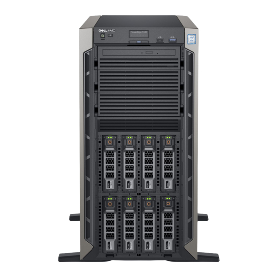
Figure 2. Front panel view of 4 x 3.5-inch cabled drive system Table 1. Front panel features Item Components Icon Description Indicates if the system is turned on or off. Press the power button to manually Power button turn on or off the system. Dell EMC PowerEdge T440 system overview... - Page 11 Enable you to install drives that are supported on your system. For more information about drives, see Technical specifications. Drive slot Enables you to install TBUs for 8x and 16x backplane configurations, or drive blank in the empty drive slot to maintain proper system cooling. Dell EMC PowerEdge T440 system overview...
- Page 12 The System Identification (ID) button is available on the front and back of the System identification systems. Press the button to identify a system in a rack by turning on the button Dell EMC PowerEdge T440 system overview...
- Page 13 Physical drives 3.5-inch drives and 2.5-inch drives/SSDs. Figure 4. Front panel view of 8 x 3.5-inch hot swappable drive system in rack mode Dell EMC PowerEdge T440 system overview...
- Page 14 Enables you to install TBUs for 8x and 16x backplane configurations, or drive blank in the empty drive slot to maintain proper system cooling. Physical drives 3.5-inch drives and 2.5-inch drives/SSDs. Rack ear Enables you to convert the tower system to a rack system. Dell EMC PowerEdge T440 system overview...
- Page 15 Press the button to identify a system in a rack by turning on the button system ID button. You can also use the system ID button to reset iDRAC and to access BIOS using the step through mode. Dell EMC PowerEdge T440 system overview...
-
Page 16: Status Led Indicators
For more information about error messages, see the • In standby Event and Error Message Reference Guide for 14th • In any error condition For Generation Dell EMC PowerEdge Servers at example, a failed fan, PSU, or a www.dell.com/qrl. drive Dell EMC PowerEdge T440 system overview... -
Page 17: System Health And System Id Indicator Codes
Expansion card installation guidelines. System health and system ID indicator codes The system health and system ID button is on the front panel of your system. Figure 7. System health and system ID buttons Dell EMC PowerEdge T440 system overview... -
Page 18: Drive Indicator Codes
If the drive is in the Advanced Host Controller Interface (AHCI) mode, the status LED indicator does not turn on. Table 7. Drive indicator codes Drive status indicator code Condition Flashes green twice per second Identifying drive or preparing for removal. Drive ready for removal. Dell EMC PowerEdge T440 system overview... -
Page 19: Back View Of The System
NIC ports, and USB and VGA ports. Most of the expansion card ports can be accessed from the back panel. The hot swappable and cabled power supply units are accessible from the back panel. Dell EMC PowerEdge T440 system overview... - Page 20 The NIC ports are integrated on the system board provide network connectivity. For more information about the supported configurations, Technical specifications. The USB ports are 4-pin, 2.0-compliant. These ports enable you to USB 2.0 port (4) connect USB devices to the system. Dell EMC PowerEdge T440 system overview...
-
Page 21: Nic Indicator Codes
Link indicator is amber, and activity indicator is blinking The NIC is connected to a valid network at less than its maximum port green. speed, and data is being sent or received. Dell EMC PowerEdge T440 system overview... -
Page 22: Power Supply Unit Indicator Codes
Swapping the PSU to make a matched pair can result in an error condition and unexpected system shutdown. To change from a high output configuration to a low output configuration or conversely, you must turn off the system. Dell EMC PowerEdge T440 system overview... -
Page 23: Locating The Service Tag Of Your System
Enterprise Service Tag (EST) is found on the back of the system. This information is used by Dell to route support calls to the appropriate personnel. Figure 12. Locating Service Tag of your system Information tag (top view) Information tag (back view) OpenManage Mobile (OMM) label iDRAC MAC address and iDRAC secure password label Service Tag Dell EMC PowerEdge T440 system overview... -
Page 24: System Information Label
System information label Dell EMC PowerEdge T440 system overview... - Page 25 Figure 14. PowerEdge T440 – Service information Dell EMC PowerEdge T440 system overview...
-
Page 26: Documentation Resources
To view the document that is listed in the documentation resources table: • From the Dell EMC support site: Click the documentation link that is provided in the Location column in the table. Click the required product or product version. - Page 27 Dell OpenManage Essentials, see OpenManage Essentials the Dell OpenManage Essentials User’s Guide. For information about installing and using Dell www.dell.com/serviceabilitytools SupportAssist, see the Dell EMC SupportAssist Enterprise User’s Guide. For information about partner programs enterprise www.dell.com/openmanagemanuals systems management, see the OpenManage Connections Enterprise Systems Management documents.
-
Page 28: Technical Specifications
Technical specifications The technical and environmental specifications of your system are outlined in this section. Topics: • System dimensions • Chassis weight • Processor specifications • Supported operating systems • Cooling fan specifications • PSU specifications • System battery specifications •... -
Page 29: System Dimensions
System dimensions Figure 15. Dell EMC PowerEdge T440 system dimensions Table 12. Dimensions of Dell EMC PowerEdge T440 system (with bezel) 304.5 mm 218 mm (8.58 430.3 mm 443.3 mm 471.333 mm 538.4 mm 573.636 mm 37.065 mm (11.98 in) (16.94 in) -
Page 30: Processor Specifications
Processor specifications The Dell EMC PowerEdge T440 system supports up to two Intel Xeon Scalable Processor, up to 14 cores per processor. Supported operating systems The Dell EMC PowerEdge T440 system supports the following operating systems: • Canonical Ubuntu LTS •... -
Page 31: Memory Specifications
64 GB 64 GB 640 GB 128 GB 1024 GB Storage controller specifications The Dell EMC PowerEdge T440 system supports: • Internal controllers: PowerEdge Expandable RAID Controller (PERC) H730P, HBA330, H740P, H330, Software RAID (SWRAID)S140 • External PERC (RAID): H840 •... -
Page 32: Ports And Connectors Specifications
You can install up to five PCIe add-on cards. VGA ports The Video Graphic Array (VGA) port enables you to connect the system to a VGA display. The Dell EMC PowerEdge T440 system supports one 15-pin VGA ports on the back of the system. -
Page 33: Video Specifications
NOTE: The write-protect switch is on the IDSDM or vFlash module. Video specifications The Dell EMC PowerEdge T440 system supports Matrox G200eR2 graphics card with 16 MB capacity. Table 17. Supported video resolution options Resolution Refresh rate Color depth (bits) -
Page 34: Standard Operating Temperature
Table 21. Maximum shock specifications Maximum shock Specifications Operating Six consecutively executed shock pulses in the positive and negative x, y, and z axes of 6 G for up to 11 ms. Storage 6 consecutively executed shock pulses in the positive and negative x, y, and z axes (one pulse on each side of the system) of 71 G for up to 2 ms. - Page 35 Non-Dell qualified peripheral cards and/or peripheral cards greater than 25 W are not supported. • GPU is not supported. • Tape backup unit is not supported. Thermal restriction matrix Table 26. Thermal restriction matrix for Dell EMC PowerEdge T440 system Storage configuration 4x 3.5-inch cable 8x 3.5-inch drive 16x 2.5-inch drive drive...
-
Page 36: Particulate And Gaseous Contamination Specifications
Storage configuration 4x 3.5-inch cable 8x 3.5-inch drive 16x 2.5-inch drive drive Processor number TDP (W) Core count Ambient support = 35°C Intel Xeon Bronze 3106 Intel Xeon Bronze 3104 Intel Xeon Silver 4112 85 Particulate and gaseous contamination specifications The following table defines the limitations that help avoid any equipment damage or failure from particulate and gaseous contamination. -
Page 37: Initial System Setup And Configuration
Initial system setup and configuration Setting up your system Perform the following steps to set up your system: Unpack the system. Install the system into the rack. For more information about installing the system into the rack, see the Rail Installation Guide at www.dell.com/poweredgemanuals. -
Page 38: Log In To Idrac
Ensure that you change the default user name and password after setting up the iDRAC IP address. NOTE: The Intel Quick Assist Technology (QAT) on the Dell EMC PowerEdge T440 is supported with chipset integration and is enabled through an optional license. The license files are enabled on the sleds through iDRAC. -
Page 39: Downloading Drivers And Firmware
Using iDRAC virtual media www.dell.com/idracmanuals Downloading drivers and firmware Dell EMC recommends that you download and install the latest BIOS, drivers, and systems management firmware on your system. Prerequisite Ensure that you clear the web browser cache before downloading the drivers and firmware. -
Page 40: Pre-Operating System Management Applications
Pre-operating system management applications You can manage basic settings and features of a system without booting to the operating system by using the system firmware. Topics: • Options to manage the pre-operating system applications • System Setup • Dell Lifecycle Controller •... -
Page 41: System Setup Details
System Setup details The System Setup Main Menu screen details are explained as follows: Option Description System BIOS Enables you to configure BIOS settings. iDRAC Settings Enables you to configure the iDRAC settings. The iDRAC settings utility is an interface to set up and configure the iDRAC parameters by using UEFI (Unified Extensible Firmware Interface). - Page 42 Option Description to RAID mode. You might also need to change the Boot Mode setting to UEFI. Otherwise, you should set this field to Non-RAID mode. Boot Settings Provides options to specify the Boot mode (BIOS or UEFI). Enables you to modify UEFI and BIOS boot settings. Network Settings Provides options to manage the UEFI network settings and boot protocols.
- Page 43 Option Description System Specifies the current version of the Management Engine firmware. Management Engine Version System Service Tag Specifies the system Service Tag. System Specifies the name of the system manufacturer. Manufacturer System Specifies the contact information of the system manufacturer. Manufacturer Contact Information...
- Page 44 Option Description System Memory Specifies whether the system memory tests are run during system boot. Options are Enabled and Disabled. This Testing option is set to Disabled by default. Memory Operating Specifies the memory operating mode. The options available are Optimizer Mode, Single Rank Spare Mode, Multi Mode Rank Spare Mode, and Mirror Mode.
- Page 45 Option Description The options available are Maximum data rate, 10.4 GT/s, and 9.6 GT/s. This option is set to Maximum data rate by default. Maximum data rate indicates that the BIOS runs the communication links at the maximum frequency supported by the processors.
- Page 46 Option Description The following settings are displayed for each processor installed in the system: Option Description Family-Model- Specifies the family, model, and stepping of the processor as defined by Intel. Stepping Brand Specifies the brand name. Level 2 Cache Specifies the total L2 cache. Level 3 Cache Specifies the total L3 cache.
- Page 47 Option Description Option Description Model Specifies the drive model of the selected device. Drive Type Specifies the type of drive attached to the SATA port. Capacity Specifies the total capacity of the drive. This field is undefined for removable media devices such as optical drives.
- Page 48 Viewing Boot Settings To view the Boot Settings screen, perform the following steps: Power on, or restart your system. Press F2 immediately after you see the following message: F2 = System Setup NOTE: If your operating system begins to load before you press F2, wait for the system to finish booting, and then restart your system and try again.
- Page 49 Choosing system boot mode System Setup enables you to specify one of the following boot modes for installing your operating system: • BIOS boot mode is the standard BIOS-level boot interface. • UEFI boot mode (the default), is an enhanced 64-bit boot interface. If you have configured your system to boot to UEFI mode, it replaces the system BIOS.
- Page 50 Network Settings screen details The Network Settings screen details are explained as follows: Option Description UEFI PXE Settings Options Description PXE Device n (n = Enables or disables the device. When enabled, a UEFI PXE boot option is created for the 1 to 4) device.
- Page 51 Option Description User Accessible Configures the user accessible USB ports. Selecting Only Back Ports On disables the front USB ports; selecting USB Ports All Ports Off disables all front and back USB ports. The USB keyboard and mouse still function in certain USB ports during the boot process, depending on the selection.
- Page 52 Option Description Memory Mapped When set to 12 TB, the system maps the MMIO base to 12 TB. Enable this option for an OS that requires 44 bit I/O Base PCIe addressing. When set to 512 GB, the system maps the MMIO base to 512 GB, and reduces the maximum support for memory to less than 512 GB.
- Page 53 Serial Communication You can use the Serial Communication screen to view the properties of the serial communication port. Viewing Serial Communication To view the Serial Communication screen, perform the following steps: Power on, or restart your system. Press F2 immediately after you see the following message: F2 = System Setup NOTE: If your operating system begins to load before you press F2, wait for the system to finish booting, and then...
- Page 54 System Profile Settings You can use the System Profile Settings screen to enable specific system performance settings such as power management. Viewing System Profile Settings To view the System Profile Settings screen, perform the following steps: Power on, or restart your system. Press F2 immediately after you see the following message: F2 = System Setup NOTE:...
- Page 55 Option Description The CPU uses the setting to manipulate the internal behavior of the processor and determines whether to target higher performance or better power savings. This option is set to Balanced Performance by default. Number of Turbo NOTE: If there are two processors installed in the system, you will see an entry for Number of Turbo Boost Enabled Boost Enabled Cores for Processor 2.
- Page 56 Option Description Setup Password Enables you to set the system setup password. This option is read-only if the password jumper is not installed in the system. Password Status Enables you to lock the system password. This option is set to Unlocked by default. TPM Security NOTE: The TPM menu is available only when the TPM module is installed.
- Page 57 Option Description TPM Advanced This setting is enabled only when TPM Security is set to ON. Settings Intel(R) TXT Enables you to set the Intel Trusted Execution Technology (TXT) option. To enable the Intel TXT option, virtualization technology and TPM Security must be enabled with Pre-boot measurements. This option is set to Off by default.
- Page 58 Option Description Options Description Deployed Mode restricts the programmatic mode transitions. Secure Boot Policy Specifies the list of certificates and hashes that secure boot uses to authenticate images. Summary Secure Boot Configures the Secure Boot Custom Policy. To enable this option, set the Secure Boot Policy to Custom. Custom Policy Settings Creating a system and setup password...
- Page 59 NOTE: If an incorrect system password is typed, the system displays a message and prompts you to reenter your password. You have three attempts to type the correct password. After the third unsuccessful attempt, the system displays an error message that the system has stopped functioning and must be turned off.
- Page 60 Redundant OS Control In the Redundant OS Control screen you can set the redundant OS information. This enables you to set up a physical recovery disk on the system. Viewing Redundant OS Control To view the Redundant OS Control screen, perform the following steps: Power on, or restart your system.
-
Page 61: Idrac Settings Utility
Miscellaneous Settings You can use the Miscellaneous Settings screen to perform specific functions such as updating the asset tag and changing the system date and time. Viewing Miscellaneous Settings To view the Miscellaneous Settings screen, perform the following steps: Power on, or restart your system. Press F2 immediately after you see the following message: F2 = System Setup NOTE:... -
Page 62: Device Settings
For more information about using iDRAC, see Dell Integrated Dell Remote Access Controller User's Guide at www.dell.com/ poweredgemanuals. Device Settings Device Settings enables you to configure the below device parameters: • Controller Configuration Utility • Embedded NIC Port1-X Configuration • NICs in slotX, Port1-X Configuration •... -
Page 63: Boot Manager Main Menu
Boot Manager main menu Menu item Description Continue Normal The system attempts to boot to devices starting with the first item in the boot order. If the boot attempt fails, the Boot system continues with the next item in the boot order until the boot is successful or no more boot options are found. -
Page 64: Installing And Removing System Components
Installing and removing system components Safety instructions WARNING: Whenever you need to lift the system, get others to assist you. To avoid injury, do not attempt to lift the system by yourself. WARNING: Opening or removing the system cover while the system is powered on may expose you to a risk of electric shock. CAUTION: Do not operate the system without the cover for a duration exceeding five minutes. -
Page 65: Optional Front Bezel
The key is required only if your system includes a bezel. • Phillips #1 screwdriver • Phillips #2 screwdriver • Torx #T30 screwdriver • Wrist grounding strap Optional front bezel Removing the front bezel Prerequisite Follow the safety guidelines listed in Safety instructions. -
Page 66: System Feet
NOTE: There are two bezel keys attached to the back of the bezel. Insert the bezel tabs into the slots in the chassis. Press the release latch, and push the bezel toward the system until the bezel locks into place. Using the key lock the bezel. -
Page 67: Installing The System Feet
Figure 18. Removing the system feet Next step If applicable, install the system feet or the caster wheel assembly. Installing the system feet Prerequisites CAUTION: Install the feet on a stand-alone tower system to provide stability to the system. An unstable system might tip over and cause injury to the user or damage to the system. -
Page 68: Inside The System
Figure 19. Installing the system feet Next steps Place the system upright on a flat, stable surface, and rotate the system feet outward. Follow the procedure listed in After working inside your system. Inside the system NOTE: Components that are hot swappable are marked orange and touch points on the components are marked blue. Installing and removing system components... - Page 69 Figure 20. Inside the system - Cabled drive system release latch drive cage cable retention lock cabled power supply unit power supply unit cage processor 2 socket processor 1 cabled drive cage Figure 21. Inside the system - hot swappable drive system release latch drive cage Installing and removing system components...
-
Page 70: Caster Wheels - Optional
cable retention lock power interposer board power supply unit cage processor 2 socket processor 1 backplane Caster wheels – optional Removing caster wheels Prerequisites Follow the safety guidelines listed in Safety instructions. Place the system on a flat, stable surface. Extend the wheels beyond the edge of the surface. -
Page 71: Installing Caster Wheels
Installing caster wheels Prerequisites Follow the safety guidelines listed in Safety instructions. Place the system on its side on a flat, stable surface. If installed, remove the system feet. Steps Align the two retention hooks on the rear wheel unit with the two slots on the base of the system, and insert the hooks into the slots. Push the rear wheel unit toward the back of the system and using a Phillips #2 screwdriver secure the unit in place using a single screw. -
Page 72: System Cover
System cover Removing the system cover Prerequisites Follow the safety guidelines listed in Safety instructions. Turn off the system and all attached peripherals. Disconnect the system from the electrical outlet and peripherals. If installed, remove the front bezel. Place the system on a flat, stable surface. Steps Turn the latch release lock to the unlocked position. -
Page 73: Installing The System Cover
Installing the system cover Prerequisite NOTE: Ensure that all internal cables are connected and placed out of the way and no tools or extra parts are left inside the system. Follow the safety guidelines listed in Safety instructions. Steps Align the tabs on the system cover with the slots on the chassis. Press the cover release latch, and push the cover toward the chassis until the latch locks into place. -
Page 74: Air Shroud
Air shroud Removing the air shroud Prerequisites CAUTION: Never operate your system with the air shroud removed. The system may get overheated quickly, resulting in shutdown of the system and loss of data. Follow the safety guidelines listed in Safety instructions. -
Page 75: Drives
Steps Align the tabs on the air shroud with the securing slots on the chassis. Lower the air shroud into the chassis until it is firmly seated. NOTE: When the cooling shroud is properly seated, the chassis intrusion-switch on the cooling shroud connects to the chassis intrusion-switch connector on the system board. -
Page 76: Installing A Drive Blank
CAUTION: Mixing drive blanks from previous generations of PowerEdge servers is not supported. Step Press the release button, and slide the drive blank out of the drive slot. Figure 28. Removing a drive blank Next step Install a drive or a drive blank. Installing a drive blank The procedure for installing 2.5-inch and 3.5-inch drive blanks is identical. -
Page 77: Removing A Drive Carrier
Figure 29. Installing a drive blank Next step If removed, install the bezel. Removing a drive carrier Prerequisites Follow the safety guidelines listed in Safety instructions. If applicable, remove the front bezel. Using the management software, prepare the drive for removal. If the drive is online, the green activity or fault indicator flashes while the drive is turning off. -
Page 78: Installing A Drive Carrier
Figure 30. Removing a drive carrier Next steps Follow the procedure listed in After working inside your system. Install a drive carrier. If you are not replacing the drive immediately, insert a drive blank in the empty drive slot to maintain proper system cooling. Installing a drive carrier Prerequisites CAUTION:... -
Page 79: Removing The Drive From The Drive Carrier
Figure 31. Installing a drive carrier Next step If applicable, install the bezel. Removing the drive from the drive carrier Prerequisite Follow the safety guidelines listed in Safety instructions. CAUTION: Mixing drives from previous generations of PowerEdge servers is not supported. Steps Using a Phillips #1 screwdriver, remove the screws from the slide rails on the drive carrier. -
Page 80: Installing A Drive Into The Drive Carrier
Figure 32. Removing the drive from the drive carrier Next step If applicable, Install the drives into their original slots. Installing a drive into the drive carrier Prerequisites Follow the safety guidelines listed in Safety instructions. CAUTION: Mixing drive carriers from other generations of PowerEdge servers is not supported. NOTE: When installing a drive into the drive carrier, ensure that the screws are torqued to 4 in-lbs. -
Page 81: Removing A 2.5-Inch Drive From A 3.5-Inch Drive Adapter
Figure 33. Installing a drive into the drive carrier Removing a 2.5-inch drive from a 3.5-inch drive adapter Prerequisites Follow the safety guidelines listed in Safety instructions. Remove the 3.5-inch drive adapter from the 3.5-inch hot swappable drive carrier. NOTE: A 2.5-inch drive is installed in a 3.5-inch drive adapter, which is then installed in the 3.5-inch drive carrier. -
Page 82: Installing A 2.5-Inch Drive Into A 3.5-Inch Drive Adapter
Figure 34. Removing a 2.5-inch drive from a 3.5-inch drive adapter Next step Install a 2.5-inch drive into a 3.5-inch drive adapter. Installing a 2.5-inch drive into a 3.5-inch drive adapter Prerequisites Follow the safety guidelines listed in Safety instructions. Remove the 3.5-inch drive adapter from the 3.5-inch hot swappable drive carrier. -
Page 83: Removing A 3.5-Inch Drive Adapter From A 3.5-Inch Drive Carrier
Figure 35. Installing a 2.5-inch drive into a 3.5-inch drive adapter Removing a 3.5-inch drive adapter from a 3.5-inch drive carrier Prerequisites Follow the safety guidelines listed in Safety instructions. If installed, remove the front bezel. Remove the 3.5-inch drive carrier from the system. -
Page 84: Installing A 3.5-Inch Drive Adapter Into The 3.5-Inch Drive Carrier
Figure 36. Removing a 3.5-inch drive adapter from a 3.5-inch drive carrier Next step Install the 3.5-inch drive carrier or install the 3.5-inch drive adapter into the 3.5-inch drive carrier. Installing a 3.5-inch drive adapter into the 3.5-inch drive carrier Prerequisites Follow the safety guidelines listed in Safety... -
Page 85: Optical Drives And Tape Drives
Figure 37. Installing a 3.5-inch drive adapter into the 3.5-inch drive carrier Next steps Installing a 2.5-inch drive into a 3.5-inch drive adapter. If removed, install the front bezel. Optical drives and tape drives Removing the optical or tape drive blank Prerequisites Follow the safety guidelines listed in Safety... -
Page 86: Installing The Optical Or Tape Drive Blank
Figure 38. Removing the optical drive or tape drive blank Next steps Install the optical drive cage or tape drive. If applicable, install the bezel. Installing the optical or tape drive blank Prerequisites Follow the safety guidelines listed in Safety instructions. -
Page 87: Removing The Optical Drive Cage Or Tape Drive
Figure 39. Installing the optical or tape drive blank Next steps Follow the procedure listed in After working inside your system. If applicable, install the bezel. Removing the optical drive cage or tape drive Prerequisites NOTE: The procedure to remove the optical drive cage is identical to removing a tape drive. Follow the safety guidelines listed in Safety instructions. -
Page 88: Installing The Optical Drive Cage Or Tape Drive
Figure 40. Removing the optical drive cage or tape drive Next step Install the optical drive cage or tape drive. Installing the optical drive cage or tape drive Prerequisite NOTE: The procedure to install the optical drive cage is the same as installing the tape drive. Follow the safety guidelines listed in Safety instructions. -
Page 89: Cabled Drives
Figure 41. Installing the optical drive cage or tape drive Next steps Follow the procedure listed in After working inside your system. If applicable, install the bezel. Cabled drives CAUTION: Do not turn off or restart your system while the drive is being formatted. Doing so can cause a drive failure. Removing the internal hard drive bay Prerequisites Follow the safety guidelines listed in... -
Page 90: Installing The Internal Hard Drive Bay
Figure 42. Removing the internal hard drive bay Next step Follow the procedure listed in After working inside your system. Installing the internal hard drive bay Prerequisites Follow the safety guidelines listed in Safety instructions. Follow the procedure listed in Before working inside your system. -
Page 91: Removing A Cabled Drive
Figure 43. Installing the internal hard drive bay Next steps Follow the procedure listed in After working inside your system. Connect the data and power cables to the hard drive(s). Removing a cabled drive Prerequisites Follow the safety guidelines listed in Safety instructions. -
Page 92: Installing A Cabled Drive
Figure 44. Removing a cabled drive Next steps Follow the procedure listed in After working inside your system. Install the internal drive bay into the chassis. If disconnected, reconnect the power and data cable(s) to the remaining drive(s) in the internal drive bay. Installing a cabled drive Prerequisites Follow the safety guidelines listed in... -
Page 93: Drive Backplane
Figure 45. Installing a cabled drive Next steps Install the internal drive bay into the chassis. Follow the procedure listed in After working inside your system. Enter System Setup and ensure that the drive controller is enabled. Exit System Setup and restart the system. Install any software required for operating the drive as described in the documentation for the drive. - Page 94 Figure 46. x8 drive backplane ODD power connector backplane P4 power connector backplane sideband signal connector Mini SAS SAS_A0 Mini SAS SAS_B0 Installing and removing system components...
- Page 95 Figure 47. x16 drive backplane backplane P4 power connector backplane power connector backplane power connector for optical and tape drives signal connector Mini SAS HD SAS_A0 Mini SAS HD SAS_B0 I2C Connector Installing and removing system components...
-
Page 96: Backplane Cable Routing
Backplane cable routing Cable routing - 8 x 3.5 inch drive backplane cable retention latch SATA cable (BP: BP_A0 to MB: SATA_A) SATA cable (BP: BP_B0 to MB: SATA_B) drive backplane Installing and removing system components... - Page 97 Figure 48. Cable routing - 8 x 3.5 inch drive backplane with internal PERC cable retention latch SAS cable (BP: BP_A0 to internal PERC) SAS cable (BP: BP_B0 to internal PERC) internal PERC drive backplane Installing and removing system components...
- Page 98 Figure 49. Cable routing -16 x 2.5 inch drive backplane with internal PERC cable retention latch SAS cable (BP: BP_A0 to internal PERC) SAS cable (BP: BP_B0 to internal PERC) internal PERC drive backplane Installing and removing system components...
-
Page 99: Removing A Hard Drive Backplane
Figure 50. Cable routing - 4 x 3.5 inch cabled HDD cable retention latch signal cable cabled HDD Removing a hard drive backplane Prerequisites CAUTION: To prevent damage to the drives and backplane, you must remove the hard drives from the system before removing the backplane. -
Page 100: Installing A Hard Drive Backplane
Figure 51. Removing a backplane Next step Install a hard drive backplane. Installing a hard drive backplane Prerequisites Follow the safety guidelines listed in Safety instructions. Follow the procedure listed in Before working inside your system. If installed, remove the front bezel. -
Page 101: System Memory
Figure 52. Installing a hard drive backplane Next steps Install the air shroud. Install the drives into their original slots. If applicable, install the bezel. Follow the procedure listed in After working inside your system. System memory System memory guidelines The PowerEdge systems support DDR4 Registered DIMMs (RDIMMs), and Load Reduced DIMMs (LRDIMMs). - Page 102 Figure 53. System memory view Table 36. Memory channels Processor Channel 0 Channel 1 Channel 2 Channel 3 Channel 4 Channel 5 Processor 1 Slots A1 and A7 Slots A2 and A8 Slots A3 Slots A4 and A9 Slots A5 and A10 Slots A6 Processor 2 Slots B1...
-
Page 103: General Memory Module Installation Guidelines
Table 37. Memory population DIMM Type DIMMs Populated/ Operating Frequency (in MT/s) Maximum DIMM Rank/Channel Voltage Channel RDIMM 2666, 2400, 2133, 1866 Dual rank or single rank 1.2 V 2666, 2400, 2133, 1866 Dual rank or single rank LRDIMM 2666, 2400, 2133, 1866 Quad rank 1.2 V 2666, 2400, 2133, 1866... -
Page 104: Mode-Specific Guidelines
DIMM population update for Performance Optimized mode with quantity of 4 and 8 DIMMs per processor. • When the DIMM quantity is 4 per processor, the population is slot 1, 2, 4, 5. • When the DIMM quantity is 8 per processor, the population is slot 1, 2, 4, 5, 7, 8, 9, 10. Mode-specific guidelines The configurations allowed depend on the memory mode selected in the System BIOS. - Page 105 Memory Operating Mode Description Dell Fault Resilient Mode The Dell Fault Resilient Mode if enabled, the BIOS creates an area of memory that is fault resilient. This mode can be used by an OS that supports the feature to load critical applications or enables the OS kernel to maximize system availability.
-
Page 106: Removing A Memory Module
Processor Configuration Memory population Memory population information NOTE: Odd number of DIMMs will result in unbalanced memory configurations, which in turn will result in performance loss. It is recommended to populate all memory channels identically with identical DIMMs for best performance. •... -
Page 107: Installing A Memory Module
Figure 54. Removing a memory module Next steps Install the memory module. If you are removing the memory module permanently, install a memory module blank. The procedure to install a memory module blank is similar to that of the memory module. Installing a memory module Prerequisite Follow the safety guidelines listed in... -
Page 108: Cooling Fans
Figure 55. Installing a memory module Next steps Install the air shroud Follow the procedure listed in After working inside your system. To verify if the memory module has been installed properly, press F2 and navigate to System Setup Main Menu > System BIOS > Memory Settings. -
Page 109: Installing The Internal Cooling Fan
Figure 56. Removing the internal cooling fan Next steps Follow the procedure listed in After working inside your system. Install the internal cooling fan. Installing the internal cooling fan Prerequisites Follow the safety guidelines listed in Safety instructions. Follow the procedure listed in Before working inside your system. -
Page 110: Removing The External Cooling Fan
Follow the procedure listed in After working inside your system. Removing the external cooling fan Prerequisites Follow the safety guidelines listed in Safety instructions. Follow the procedure listed in Before working inside your system. Remove the air shroud. Steps Disconnect the external cooling fan power cable from the system board. Remove the four screws that secure the external cooling fan to the chassis. -
Page 111: Optional Internal Usb Memory Key
Figure 59. Installing the external cooling fan Next steps Install the air shroud. Follow the safety guidelines listed in After working inside your system. Optional internal USB memory key Replacing the optional internal USB memory key Prerequisites CAUTION: To avoid interference with other components in the server, the maximum permissible dimensions of the USB memory key are 15.9 mm wide x 57.15 mm long x 7.9 mm high. -
Page 112: Installing The Expansion Card Holder
Follow the procedure listed in Before working inside your system. Remove the air shroud. Step Press the tab and remove the expansion-card holder from the chassis. Figure 60. Removing the expansion card holder Next steps Install the air shroud. Follow the procedure listed in After working inside your system. -
Page 113: Expansion Cards
Figure 61. Installing the expansion card holder Next steps Follow the procedure listed in After working inside your system. Install the air shroud. Expansion cards Expansion card installation guidelines The following table describes the supported expansion cards: Table 40. Supported PCI express generation 3 expansion cards PCIe Slot Processor Connection Height... -
Page 114: Removing A Expansion Card
• Two double-width GPU cards on a single processor configuration and four double width GPU cards on a dual processor configuration do not support any other add-on cards. • Specific GPU cards will need the use of the dongle power cable. GPU card installation restrictions •... -
Page 115: Installing An Expansion Card
Figure 63. Installing the filler bracket Next steps Follow the procedure listed in After working inside your system. Install an expansion card. Install the expansion card holder. Install the air shroud. Installing an expansion card Prerequisites Follow the safety guidelines listed in Safety instructions. -
Page 116: M.2 Ssd Module
Figure 64. Removing the filler bracket Figure 65. Installing an expansion card Next steps Follow the procedure listed in After working inside your system. Install the expansion card holder. Install the air shroud. M.2 SSD module Removing the M.2 SSD module Prerequisites Follow the safety guidelines listed in Safety... -
Page 117: Installing The M.2 Ssd Module
Steps Loosen the screw and lift the retention strap that secures the M.2 SSD module on the BOSS card. Lift the M.2 SSD module and slide it out of the connector on the BOSS card. Figure 66. Removing the M.2 SSD module Next step Replace the M.2 SSD module. -
Page 118: Optional Idsdm Or Vflash Module
Figure 67. Installing the M.2 SSD module Next steps Install the BOSS card. NOTE: The procedure to install the BOSS card is similar to the removing an expansion card. Install the applicable air shroud. Follow the procedure listed in After working inside your system. -
Page 119: Installing The Microsd Card
Installing the MicroSD card Prerequisites Follow the safety guidelines listed in Safety instructions. NOTE: To use an MicroSD card with your system, ensure that the Internal SD Card Port is enabled in System Setup. NOTE: If reinstalling, ensure that you install the MicroSD cards into the same slots based on the labels you had marked on the cards during removal. -
Page 120: Installing Optional Idsdm Or Vflash Card
Figure 68. Removing the optional IDSDM/vFlash card NOTE: There are two dip switches on the IDSDM/vFlash card for write-protection. Next step Install the optional IDSDM/vFlash card. Installing optional IDSDM or vFlash card Prerequisite Follow the safety guidelines listed in Safety instructions. -
Page 121: Processors And Heat Sinks
Figure 69. Installing optional IDSDM/vFlash card Next steps Install the MicroSD cards. NOTE: Reinstall the MicroSD cards into the same slots based on the labels you had marked on the cards during removal. Follow the procedure listed in After working inside your system. -
Page 122: Removing The Processor From The Processor And Heat Sink Module
Set the PHM aside with the processor side facing up. Figure 70. Removing the processor and heat sink module Next step Install the processor and heat sink module. Removing the processor from the processor and heat sink module Prerequisites NOTE: Only remove the processor from the processor and heat sink module if you are replacing the processor or heat sink. - Page 123 Remove the air shroud. Remove the processor and heat sink module. Steps Place the heat sink with the processor side facing up. Insert a flat blade screwdriver into the release slot marked with a yellow label. Twist (do not pry) the screwdriver to break the thermal paste seal.
-
Page 124: Installing The Processor Into A Processor And Heat Sink Module
Figure 72. Removing the processor bracket Next step Install the processor into the processor and heat sink module. Installing the processor into a processor and heat sink module Prerequisite Follow the safety guidelines listed in Safety instructions. Steps Place the processor in the processor tray. NOTE: Ensure that the pin 1 indicator on the processor tray is aligned with the pin 1 indicator on the processor. - Page 125 Figure 73. Installing the processor bracket If you are using an existing heat sink, remove the thermal grease from the heat sink by using a clean lint-free cloth. Use the thermal grease syringe included with your processor kit to apply the grease in a quadrilateral design on the top of the processor.
- Page 126 Place the heat sink on the processor and push down on the base of the heat sink until the bracket locks onto the heat sink. NOTE: • Ensure that the two guide pin holes on the bracket match the guide holes on the heat sink. •...
-
Page 127: Installing A Processor And Heat Sink Module
Installing a processor and heat sink module Prerequisites CAUTION: Never remove the heat sink from a processor unless you intend to replace the processor. The heat sink is necessary to maintain proper thermal conditions. Follow the safety guidelines listed in Safety instructions. -
Page 128: Power Supply Units
Figure 76. Installing a processor and heat sink module Next steps Install the air shroud. Follow the procedure listed in After working inside your system. Power supply units NOTE: For more information, see the Technical specifications section. CAUTION: If two PSUs are installed, both the PSUs must have the same type of label. For example, Extended Power Performance (EPP) label. -
Page 129: Removing A Power Supply Unit Blank
NOTE: When two identical PSUs are installed, power supply redundancy (1+1 – with redundancy or 2+0 – without redundancy) is configured in system BIOS. In redundant mode, power is supplied to the system equally from both PSUs when Hot Spare is disabled. -
Page 130: Removing A Power Supply Unit
Figure 78. Installing a power supply unit blank Next step Follow the procedure listed in After working inside your system. Removing a power supply unit Prerequisites CAUTION: The system needs one power supply unit (PSU) for normal operation. On power-redundant systems, remove and replace only one PSU at a time in a system that is powered on. -
Page 131: Installing A Power Supply Unit
Installing a power supply unit Prerequisites Follow the safety guidelines listed in Safety instructions. For systems that support redundant PSU, ensure that both the PSUs are of the same type and have the same maximum output power. NOTE: The maximum output power (shown in watts) is listed on the PSU label. Step Slide the PSU into the system until the PSU is fully seated and the release latch snaps into place. -
Page 132: Installing A Cabled Power Supply Unit
Steps Disconnect all the power cables from the power supply unit (PSU). Remove the screw securing the PSU to the chassis and slide the PSU out of the PSU cage. Figure 81. Removing a cabled PSU Next steps Install a cabled power supply unit. -
Page 133: Power Interposer Board
Figure 82. Installing a cabled PSU Next step Follow the procedure listed in After working inside your system. Power interposer board Removing the power interposer board Prerequisites Follow the safety guidelines listed in Safety instructions. Follow the procedure listed in Before working inside your system. -
Page 134: Installing The Power Interposer Board
Next step Follow the procedure listed in After working inside your system. Installing the power interposer board Prerequisite CAUTION: Many repairs may only be done by a certified service technician. You should only perform troubleshooting and simple repairs as authorized in your product documentation, or as directed by the online or telephone service and support team. Damage due to servicing that is not authorized by Dell is not covered by your warranty. -
Page 135: System Battery
Install the PSUs or PSU blank. Follow the procedure listed in After working inside your system. System battery Replacing the system battery Prerequisites WARNING: There is a danger of a new battery exploding if it is incorrectly installed. Replace the battery only with the same or equivalent type recommended by the manufacturer. -
Page 136: Control Panel Assembly
Enter the correct time and date in the System Setup Time and Date fields. Exit the System Setup. Control panel assembly Removing the control panel assembly Prerequisites Follow the safety guidelines listed in Safety instructions. Follow the procedure listed in Before working inside your system. -
Page 137: Installing The Control Panel Assembly
Installing the control panel assembly Prerequisite Follow the safety guidelines listed in Safety instructions. Steps Replace the blank information tag in the new control panel with the information tag retained from the old control panel. Figure 88. Installing the information tag Figure 89. -
Page 138: System Board
Align and insert the control panel into the control panel slot in the chassis. Secure the control panel to the chassis by using the screw. Connect the control panel cable and the control panel USB cable to the system board. Next step Follow the procedure listed in After working inside your... - Page 139 Figure 90. System board screws Holding the post, incline the system board at an angle, and lift the system board out of the chassis. Installing and removing system components...
-
Page 140: Installing The System Board
Figure 91. Removing the system board Next step Replace or Install the system board. Installing the system board Prerequisite Follow the safety guidelines listed in Safety instructions. Steps Unpack the new system board assembly. CAUTION: Do not lift the system board by holding a memory module, processor, or other components. CAUTION: Take care not to damage the system identification button while placing the system board into the system. - Page 141 Figure 92. Installing the system board Using the Phillips #2 screwdriver secure the system board to the chassis with screws. Next steps Replace the following: Trusted Platform Module (TPM) Memory modules Processors and heat sink modules Internal USB key vFlash/IDSDM module Integrated storage controller card Expansion cards, if installed Expansion card holder...
-
Page 142: Restoring The System Using Easy Restore
Restoring the system using Easy Restore The easy restore feature enables you to restore your service tag, license, UEFI configuration, and the system configuration data after replacing the system board. All data is backed up in a backup flash device automatically. If BIOS detects a new system board, and the service tag in the backup flash device, BIOS prompts the user to restore the backup information. -
Page 143: Initializing Tpm For Bitlocker Users
About this task CAUTION: If you are using the Trusted Platform Module (TPM) with an encryption key, you may be prompted to create a recovery key during program or System Setup. Work with the customer to create and safely store this recovery key. When replacing this system board, you must supply the recovery key when you restart your system or program before you can access the encrypted data on your hard drives. -
Page 144: Initializing The Tpm 1.2 For Txt Users
The TPM Status changes to Enabled, Activated. Initializing the TPM 1.2 for TXT users While booting your system, press F2 to enter System Setup. On the System Setup Main Menu screen, click System BIOS > System Security Settings. From the TPM Security option, select On with Pre-boot Measurements. From the TPM Command option, select Activate. -
Page 145: Updating Bios
Figure 94. Installing the system ears Next steps Install the system cover. Install the system in the rack. For more information, see the Rack Installation Guide that is shipped with your system. Follow the procedure listed in After working inside your system. -
Page 146: Using System Diagnostics
Using system diagnostics If you experience a problem with your system, run the system diagnostics before contacting Dell for technical assistance. The purpose of running system diagnostics is to test your system hardware without using additional equipment or risking data loss. If you are unable to fix the problem yourself, service and support personnel can use the diagnostics results to help you solve the problem. -
Page 147: System Diagnostic Controls
System diagnostic controls Menu Description Configuration Displays the configuration and status information of all detected devices. Results Displays the results of all tests that are run. System health Provides the current overview of the system performance. Event log Displays a time-stamped log of the results of all tests run on the system. This is displayed if at least one event description is recorded. -
Page 148: Jumpers And Connectors
Jumpers and connectors This topic provides specific information about the jumpers. It also provides some basic information about jumpers and switches and describes the connectors on the various boards in the system. Jumpers on the system board help to disable the system and setup passwords. -
Page 149: System Board Jumpers And Connectors
System board jumpers and connectors Figure 95. T440 system board jumpers and connectors Table 41. System board connectors Item Connector Description DIMMs for Processor 1 channels 0,1,2,3,4,5 Memory slots A1-A10 for Processor 1 Intrusion switch Intrusion switch connector SATA B Onboard SATA B connector Backplane signal Backplane signal connector... -
Page 150: System Board Jumper Settings
Item Connector Description ODD power connector ODD power System power connector System power PIB signal 2 connector PIB signal 2 IDSDM+VFlash connector IDSDM+VFlash PIB signal 1 connector PIB signal 1 SATA A connector SATA A Internal USB 3.0 connector Internal USB 3.0 Coin cell battery COIN Cell BATTERY NVRAM_CLR... -
Page 151: Disabling Forgotten Password
Jumper Setting Description NVRAM_CLR The BIOS configuration settings are retained at system boot. The BIOS configuration settings are cleared at system boot. Disabling forgotten password The software security features of the system include a system password and a setup password. The password jumper enables or disables password features and clears any password(s) currently in use. -
Page 152: Getting Help
The Contact Technical Support page is displayed with details to call, chat, or e-mail the Dell EMC Global Technical Support team. Documentation feedback You can rate the documentation or write your feedback on any of our Dell EMC documentation pages and click Send Feedback to send your feedback. Accessing system information by using QRL You can use the Quick Resource Locator (QRL) located on the information tag in the front of the T440, to access the information about the Dell EMC PowerEdge T440. -
Page 153: Quick Resource Locator For Dell Emc Poweredge T440 System
Receiving automated support with SupportAssist Dell EMC SupportAssist is an optional Dell EMC Services offering that automates technical support for your Dell EMC server, storage, and networking devices. By installing and setting up a SupportAssist application in your IT environment, you can receive the following benefits: •... -
Page 154: Recycling Or End-Of-Life Service Information
Recycling or End-of-Life service information Take back and recycling services are offered for this product in certain countries. If you want to dispose of system components, visit www.dell.com/recyclingworldwide and select the relevant country. Getting help...
Need help?
Do you have a question about the PowerEdge T440 and is the answer not in the manual?
Questions and answers