
Related Manuals for Dell EMC PowerEdge T640


Summary of Contents for Dell EMC PowerEdge T640
- Page 1 Dell EMC PowerEdge T640 Installation and Service Manual Regulatory Model: E47S Series Regulatory Type: E47S001...
- Page 2 Notes, cautions, and warnings NOTE: A NOTE indicates important information that helps you make better use of your product. CAUTION: A CAUTION indicates either potential damage to hardware or loss of data and tells you how to avoid the problem. WARNING: A WARNING indicates a potential for property damage, personal injury, or death.
-
Page 3: Table Of Contents
Contents 1 Dell EMC PowerEdge T640 overview......................8 Supported configurations..............................9 Front view of the system..............................10 Status LED indicators..............................12 iDRAC Direct LED indicator codes..........................13 iDRAC Quick Sync 2 indicator codes........................14 System health and system ID indicator codes......................15 Drive indicator codes..............................16 Back view of the system..............................17... - Page 4 Setting up your system..............................37 iDRAC configuration.................................37 Options to set up iDRAC IP address........................37 Log in to iDRAC................................38 Options to install the operating system.........................38 Methods to download firmware and drivers......................38 Downloading drivers and firmware.......................... 39 4 Pre-operating system management applications..................40 Options to manage the pre-operating system applications..................40 System Setup...................................
- Page 5 Installing a 3.5 inch drive adapter into the 3.5 inch drive carrier................77 Removing a 2.5 inch drive from a 3.5 inch drive adapter..................78 Installing a 2.5 inch drive into a 3.5 inch drive adapter..................79 Power supply units................................80 PSU specifications..............................80 Hot spare feature................................81 Removing a power supply unit blank........................81 Installing a power supply unit blank..........................82...
- Page 6 Installing the NVDIMM-N battery.......................... 108 System memory................................109 System memory guidelines............................109 General memory module installation guidelines......................111 NVDIMM-N memory module installation guidelines .................... 112 Mode-specific guidelines............................113 Removing a memory module........................... 116 Installing a memory module............................117 Processors and heat sinks..............................118 Removing a processor and heat sink module......................118 Removing the processor from the processor and heat sink module..............
- Page 7 Running the Embedded System Diagnostics from the Dell Lifecycle Controller..........166 System diagnostic controls............................167 7 Getting help..............................168 Contacting Dell EMC..............................168 Documentation feedback.............................. 168 Accessing system information by using QRL......................168 Quick Resource Locator for PowerEdge T640.....................169 Receiving automated support with SupportAssist ....................169 Recycling or End-of-Life service information......................169 Contents...
-
Page 8: Dell Emc Poweredge T640 Overview
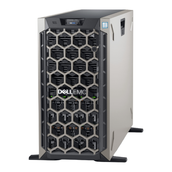
Dell EMC PowerEdge T640 overview The Dell EMC PowerEdge T640 is a dual-socket, 5U rackable tower server that supports up to: • Two Intel Xeon Scalable processors • 24 DIMM slots (support for DDR4 RDIMM, LR-DIMM) or 12 NVDIMM-N (one DIMM per channel) are supported •... -
Page 9: Supported Configurations
Supported configurations Figure 1. Supported configurations of the PowerEdge T640 Dell EMC PowerEdge T640 overview... -
Page 10: Front View Of The System
Information tag iDRAC Quick Sync 2 wireless indicator (optional) Status LED indicators System health and system ID indicator USB port (USB 2.0-compliant) USB port (USB 3.0-compliant) iDRAC Direct (Micro-AB USB) port Optical drive (optional) Drive slots Dell EMC PowerEdge T640 overview... - Page 11 Information tag iDRAC Quick Sync 2 wireless indicator (optional) Status LED indicators System health and system ID indicator USB port (USB 2.0-compliant) USB port (USB 3.0-compliant) iDRAC Direct (Micro-AB USB) port Optical drive (optional) Drive slots Dell EMC PowerEdge T640 overview...
-
Page 12: Status Led Indicators
Description Condition Corrective action PCIe indicator The indicator turns Restart the system. Update any required drivers for the PCIe card. Reinstall solid amber if a PCIe the card. If the problem persists, see Getting help. Dell EMC PowerEdge T640 overview... -
Page 13: Idrac Direct Led Indicator Codes
You can configure iDRAC Direct by using a USB to micro USB (type AB) cable, which you can connect to your laptop or tablet. The following table describes iDRAC Direct activity when the iDRAC Direct port is active: Dell EMC PowerEdge T640 overview... -
Page 14: Idrac Quick Sync 2 Indicator Codes
Restart the system. If the problem persists, see the mode. Getting help section. Blinking amber Indicates that the iDRAC Quick Sync 2 Restart the system. If the problem persists, see the hardware is not responding properly. Getting help section. Dell EMC PowerEdge T640 overview... -
Page 15: System Health And System Id Indicator Codes
Indicates that the system is experiencing a fault. Check the System Event Log for specific error messages. For information about the event and error messages generated by the system firmware and agents that monitor system components, see the Error Code Lookup page at qrl.dell.com. Dell EMC PowerEdge T640 overview... -
Page 16: Drive Indicator Codes
Flashes amber four times per second Drive failed. Flashes green slowly Drive rebuilding. Solid green Drive online. Flashes green for three seconds, amber for three seconds, and Rebuild stopped. then turns off after six seconds Dell EMC PowerEdge T640 overview... -
Page 17: Back View Of The System
Figure 9. Back view of the tower configuration PCIe expansion card slots System ID button/indicator VGA port Serial port iDRAC9 dedicated network port USB 2.0 port (2) PCIe expansion card slots NIC port (2) USB 3.0 port (4) Power supply unit (2) Dell EMC PowerEdge T640 overview... -
Page 18: Nic Indicator Codes
Each NIC on the back of the system has indicators that provide information about the activity and link status. The activity LED indicator indicates if data is flowing through the NIC, and the link LED indicator indicates the speed of the connected network. Figure 11. NIC indicator codes link LED indicator activity LED indicator Dell EMC PowerEdge T640 overview... -
Page 19: Power Supply Unit Indicator Codes
When the firmware of the PSU is being updated, the PSU handle blinks green. CAUTION: Do not disconnect the power cord or unplug the PSU when updating firmware. If firmware update is interrupted, the PSUs do not function. Dell EMC PowerEdge T640 overview... - Page 20 Power is not connected to the PSU. Blinking green When hot-plugging a PSU, the PSU indicator blinks green. This indicates that there is a PSU mismatch with respect to efficiency, feature set, health status, or supported voltage. Dell EMC PowerEdge T640 overview...
-
Page 21: Locating The Service Tag Of Your System
Enterprise Service Tag (EST) is found on the back of the system. This information is used by Dell to route support calls to the appropriate personnel. Figure 14. Locating Service Tag of your system information tag (top view) information tag (back view) OpenManage Mobile (OMM) label iDRAC MAC address and iDRAC secure password label Service Tag Dell EMC PowerEdge T640 overview... -
Page 22: System Information Label
System information label PowerEdge T640 – system information label Figure 15. LED behavior Dell EMC PowerEdge T640 overview... - Page 23 Figure 16. Configuration and layout Dell EMC PowerEdge T640 overview...
- Page 24 Dell EMC PowerEdge T640 overview Figure 17. Electrical overview...
- Page 25 Figure 18. Memory information Dell EMC PowerEdge T640 overview...
- Page 26 Dell EMC PowerEdge T640 overview...
-
Page 27: Technical Specifications
Technical specifications The technical and environmental specifications of your system are outlined in this section. Topics: • Chassis dimensions • Chassis weight • Processor specifications • Supported operating systems • Cooling fan specifications • PSU specifications • System battery specifications •... -
Page 28: Chassis Dimensions
Maximum weight (with all hard drives/SSDs) 32 x 2.5-inch 42.36 Kg (93.38 lb) 18 x 3.5-inch 49.65 Kg (109.45 lb) Processor specifications The Dell EMC PowerEdge T640 system supports up to two Intel Xeon Scalable processors, up to 28 cores per processor. Technical specifications... -
Page 29: Supported Operating Systems
For information on the restriction for fresh air condition, see the Expanded operating temperature restrictions topic in the Technical Specification section. PSU specifications The Dell EMC PowerEdge T640 system supports up to two AC or DC redundant power supply units (PSUs). Technical specifications... -
Page 30: System Battery Specifications
The Dell EMC PowerEdge T640 system supports CR 2032 3.0-V lithium coin cell system battery. Expansion bus specifications The Dell EMC PowerEdge T640 system supports PCI express (PCIe) generation 3 and 2 expansion cards. The following table describes the supported expansion cards: Table 12. -
Page 31: Memory Specifications
8 GB RDIMMs and NVDIMM-N must not be mixed. NOTE: A minimum of two processors are required for any configuration that supports NVDIMM-N DIMMs. Storage controller specifications The Dell EMC PowerEdge T640 system supports: • Internal controllers: PERC H730P, H740P, HBA330, H330, Software RAID (SWRAID) S140 •... -
Page 32: Optical Drive
The LOM (Broadcom 57416) is compatible with 10GBASE-T IEEE 802.3an and 1000 BASE-T IEEE 802.3ab. VGA ports The Video Graphic Array (VGA) port enables you to connect the system to a VGA display. The Dell EMC PowerEdge T640 system supports two 15-pin VGA ports on the front and back panels. -
Page 33: Serial Connector
Serial connector The Dell EMC PowerEdge T640 system supports one serial connector on the back panel, which is a 9-pin connector, Data Terminal Equipment (DTE), 16550-compliant. Internal Dual SD Module with vFlash card The Dell EMC PowerEdge T640 system supports Internal Dual SD module (IDSDM) and vFlash card. In 14th generation of PowerEdge servers, IDSDM and vFlash card are combined into a single card module, and are available in anyone of these configurations: •... - Page 34 Table 16. Temperature specifications Temperature Specifications Storage –40°C to 65°C (–40°F to 149°F) Continuous operation (for altitude less than 950 m or 3117 10°C to 35°C (50°F to 95°F) with no direct sunlight on the equipment. Fresh air For information about fresh air, see Expanded Operating Temperature section.
-
Page 35: Standard Operating Temperature
Operating temperature de-rating Specifications 40°C to 45°C (104°F to 113°F) Maximum temperature is reduced by 1°C/125 m (1°F/228 ft) above 950 m (3,117 ft). Standard operating temperature Table 22. Standard operating temperature specifications Standard operating temperature Specifications Continuous operation (for altitude less than 950 m or 3117 10°C to 35°C (50°F to 95°F) with no direct sunlight on the equipment. -
Page 36: Particulate And Gaseous Contamination Specifications
• Non-Dell qualified peripheral cards are not supported. • Peripheral cards consuming greater than 25 W are not supported. • 128 GB LRDIMM is supported. • NVDIMM is not supported. • Mellanox 100 GB, Mellanox Navi DP/SP, Intel FortPond Solarflare Nova, Solarflare Sunspot are not supported. Particulate and gaseous contamination specifications The following table defines the limitations that help avoid any equipment damage or failure from particulate and gaseous contamination. -
Page 37: Initial System Setup And Configuration
Initial system setup and configuration Setting up your system Perform the following steps to set up your system: Unpack the system. Install the system into the rack. For more information about installing the system into the rack, see the Rail Installation Guide at www.dell.com/poweredgemanuals. -
Page 38: Log In To Idrac
Ensure that you change the default user name and password after setting up the iDRAC IP address. NOTE: The Intel Quick Assist Technology (QAT) on the Dell EMC PowerEdge T640 is supported with chipset integration and is enabled through an optional license. The license files are enabled on the sleds through iDRAC. -
Page 39: Downloading Drivers And Firmware
Using iDRAC virtual media www.dell.com/idracmanuals Downloading drivers and firmware Dell EMC recommends that you download and install the latest BIOS, drivers, and systems management firmware on your system. Prerequisite Ensure that you clear the web browser cache before downloading the drivers and firmware. -
Page 40: Pre-Operating System Management Applications
Pre-operating system management applications You can manage basic settings and features of a system without booting to the operating system by using the system firmware. Topics: • Options to manage the pre-operating system applications • System Setup • Dell Lifecycle Controller •... -
Page 41: System Setup Details
System Setup details The System Setup Main Menu screen details are explained as follows: Option Description System BIOS Enables you to configure BIOS settings. iDRAC Settings Enables you to configure the iDRAC settings. The iDRAC settings utility is an interface to set up and configure the iDRAC parameters by using UEFI (Unified Extensible Firmware Interface). - Page 42 Option Description Network Settings Provides options to manage the UEFI network settings and boot protocols. Legacy network settings are managed from the Device Settings menu. Integrated Devices Provides options to manage integrated device controllers and ports, specifies related features and options. Serial Provides options to manage the serial ports, their related features and options.
- Page 43 Option Description System Specifies the name of the system manufacturer. Manufacturer System Specifies the contact information of the system manufacturer. Manufacturer Contact Information System CPLD Specifies the current version of the system complex programmable logic device (CPLD) firmware. Version UEFI Compliance Specifies the UEFI compliance level of the system firmware.
- Page 44 Option Description NOTE: The Memory Operating Mode option can have different default and available options based on the memory configuration of your system. NOTE: The Dell Fault Resilient Mode option establishes an area of memory that is fault resilient. This mode can be used by an operating system that supports the feature to load critical applications or enables the operating system kernel to maximize system availability.
- Page 45 Option Description Logical Processor Enables or disables the logical processors and displays the number of logical processors. If this option is set to Enabled, the BIOS displays all the logical processors. If this option is set to Disabled, the BIOS displays only one logical processor per core.
- Page 46 Option Description Processor Bus Displays the bus speed of the processor. Speed Processor n NOTE: Depending on the number of processors, there might be up to two processors listed. The following settings are displayed for each processor installed in the system: Option Description Family-Model-...
- Page 47 Option Description Port n Enables you to set the drive type of the selected device. For AHCI Mode or RAID Mode, BIOS support is always enabled. Option Description Model Specifies the drive model of the selected device. Drive Type Specifies the type of drive attached to the SATA port. Capacity Specifies the total capacity of the drive.
- Page 48 NOTE: You must use only the UEFI boot mode in order to boot from NVMe drives. • BIOS: The BIOS Boot Mode is the legacy boot mode. It is maintained for backward compatibility. Viewing Boot Settings To view the Boot Settings screen, perform the following steps: Power on, or restart your system.
- Page 49 Option Description Boot Options Enables you to select the enabled or disabled boot devices. Enable/Disable Choosing system boot mode System Setup enables you to specify one of the following boot modes for installing your operating system: • BIOS boot mode is the standard BIOS-level boot interface. •...
- Page 50 Viewing Network Settings To view the Network Settings screen, perform the following steps: Power on, or restart your system. Press F2 immediately after you see the following message: F2 = System Setup NOTE: If your operating system begins to load before you press F2, wait for the system to finish booting, and then restart your system and try again.
- Page 51 Integrated Devices You can use the Integrated Devices screen to view and configure the settings of all integrated devices including the video controller, integrated RAID controller, and the USB ports. Viewing Integrated Devices To view the Integrated Devices screen, perform the following steps: Power on, or restart your system.
- Page 52 Option Description in video and the embedded video during POST and pre-boot environment. The embedded video is disabled before the operating system boots. This option is set to Enabled by default. NOTE: When there are multiple add-in graphic cards installed in the system, the first card discovered during PCI enumeration is selected as the primary video.
- Page 53 Serial Communication You can use the Serial Communication screen to view the properties of the serial communication port. Viewing Serial Communication To view the Serial Communication screen, perform the following steps: Power on, or restart your system. Press F2 immediately after you see the following message: F2 = System Setup NOTE: If your operating system begins to load before you press F2, wait for the system to finish booting, and then...
- Page 54 System Profile Settings You can use the System Profile Settings screen to enable specific system performance settings such as power management. Viewing System Profile Settings To view the System Profile Settings screen, perform the following steps: Power on, or restart your system. Press F2 immediately after you see the following message: F2 = System Setup NOTE:...
- Page 55 Option Description Number of Turbo NOTE: If there are two processors installed in the system, you will see an entry for Number of Turbo Boost Enabled Boost Enabled Cores for Processor 2. Cores for Processor Controls the number of turbo boost enabled cores for Processor 1. The maximum number of cores is enabled by default.
- Page 56 Option Description TPM Security NOTE: The TPM menu is available only when the TPM module is installed. Enables you to control the reporting mode of the TPM. The TPM Security option is set to Off by default. You can only modify the TPM Status TPM Activation, and the Intel TXT fields if the TPM Status field is set to either On with Pre-boot Measurements or On without Pre-boot Measurements.
- Page 57 Option Description Intel(R) TXT Enables you to set the Intel Trusted Execution Technology (TXT) option. To enable the Intel TXT option, virtualization technology and TPM Security must be enabled with Pre-boot measurements. This option is set to Off by default. Power Button Enables you to set the power button on the front of the system.
- Page 58 Option Description Secure Boot Policy Specifies the list of certificates and hashes that secure boot uses to authenticate images. Summary Secure Boot Configures the Secure Boot Custom Policy. To enable this option, set the Secure Boot Policy to Custom. Custom Policy Settings Creating a system and setup password Prerequisite...
- Page 59 NOTE: If an incorrect system password is typed, the system displays a message and prompts you to reenter your password. You have three attempts to type the correct password. After the third unsuccessful attempt, the system displays an error message that the system has stopped functioning and must be turned off.
- Page 60 Redundant OS Control In the Redundant OS Control screen you can set the redundant OS information. This enables you to set up a physical recovery disk on the system. Viewing Redundant OS Control To view the Redundant OS Control screen, perform the following steps: Power on, or restart your system.
-
Page 61: Idrac Settings Utility
Miscellaneous Settings You can use the Miscellaneous Settings screen to perform specific functions such as updating the asset tag and changing the system date and time. Viewing Miscellaneous Settings To view the Miscellaneous Settings screen, perform the following steps: Power on, or restart your system. Press F2 immediately after you see the following message: F2 = System Setup NOTE:... -
Page 62: Device Settings
For more information about using iDRAC, see Dell Integrated Dell Remote Access Controller User's Guide at www.dell.com/ poweredgemanuals. Device Settings Device Settings enables you to configure the below device parameters: • Controller Configuration Utility • Embedded NIC Port1-X Configuration • NICs in slotX, Port1-X Configuration •... -
Page 63: Boot Manager Main Menu
Boot Manager main menu Menu item Description Continue Normal The system attempts to boot to devices starting with the first item in the boot order. If the boot attempt fails, the Boot system continues with the next item in the boot order until the boot is successful or no more boot options are found. -
Page 64: Installing And Removing System Components
Installing and removing system components The following sections contain the procedures for removing and replacing system components. Safety instructions WARNING: Whenever you need to lift the system, get others to assist you. To avoid injury, do not attempt to lift the system by yourself. -
Page 65: Removing The Front Bezel
Removing the front bezel Prerequisite Follow the safety guidelines listed in Safety instructions. Steps Unlock the bezel. Press the blue release latch at the top of the bezel to release the bezel from the system. Pull the top end of the bezel away from the system. Unhook the bezel tabs from the slots at the bottom of the system, and lift the bezel away. -
Page 66: System Feet
Figure 22. Installing the front bezel System feet Removing the system feet Prerequisites NOTE: It is recommended that you remove the system feet only when you are converting the system from the tower mode to the rack mode, or when you are replacing the system feet with the wheel assembly. Follow the safety guidelines listed in Safety instructions. -
Page 67: Installing The System Feet
Figure 23. Removing the system feet Next step Install the system feet install the castor wheels. Installing the system feet Prerequisites CAUTION: Install the feet on a stand-alone tower system to provide stability to the system. An unstable system might tip over and cause injury to the user or damage to the system. -
Page 68: Caster Wheels - Optional
Figure 24. Installing the system feet Next steps Place the system upright on a flat, stable surface, and rotate the system feet outward. Follow the procedure listed in After working inside your system. Caster wheels – optional Removing caster wheels Prerequisites Follow the safety guidelines listed in Safety... -
Page 69: Installing Caster Wheels
Figure 25. Removing caster wheels Next step Install the caster wheels the system feet, as applicable. Installing caster wheels Prerequisites Follow the safety guidelines listed in Safety instructions. Place the system on its side on a flat, stable surface. If installed, remove the system feet. -
Page 70: Drives
Figure 26. Installing caster wheels Next step Follow the procedure listed in Before working inside your system. Drives Removing a drive blank The procedure for removing 2.5 inch and 3.5 inch drive blanks is identical. Prerequisites Follow the safety guidelines listed in Safety instructions. -
Page 71: Installing A Drive Blank
Figure 27. Removing a drive blank Next step Install a drive drive blank. Installing a drive blank The procedure for installing 2.5 inch and 3.5 inch drive blanks is identical. Prerequisites Follow the safety guidelines listed in Safety instructions. If installed, remove the front bezel. -
Page 72: Removing A Drive Carrier
Figure 28. Installing a drive blank Next step If removed, install the front bezel. Removing a drive carrier Prerequisites Follow the safety guidelines listed in Safety instructions. If applicable, remove the front bezel Using the management software, prepare the drive for removal. If the drive is online, the green activity or fault indicator flashes while the drive is turning off. -
Page 73: Installing A Drive Carrier
Figure 29. Removing a drive carrier Next steps Installing a drive carrier. If you are not replacing the drive immediately, insert a drive blank in the empty drive slot to maintain proper system cooling. Installing a drive carrier Prerequisites CAUTION: Before attempting to remove or install a drive while the system is running, see the documentation for the storage controller card to ensure that the host adapter is configured correctly to support drive removal and insertion. -
Page 74: Removing The Drive From The Drive Carrier
Figure 30. Installing a drive carrier Next step If removed, install the front bezel. Removing the drive from the drive carrier Prerequisite Follow the safety guidelines listed in Safety instructions. CAUTION: Mixing drives from previous generations of PowerEdge servers is not supported. Steps Using a Phillips #1 screwdriver, remove the screws from the slide rails on the drive carrier. -
Page 75: Installing A Drive Into The Drive Carrier
Figure 31. Removing the drive from the drive carrier Next step Installing the drive into the drive carrier. Installing a drive into the drive carrier Prerequisites Follow the safety guidelines listed in Safety instructions. CAUTION: Mixing drive carriers from other generations of PowerEdge servers is not supported. NOTE: When installing a drive into the drive carrier, ensure that the screws are torqued to 4 in-lbs. -
Page 76: Removing A 3.5 Inch Drive Adapter From A 3.5 Inch Drive Carrier
Figure 32. Installing a drive into the drive carrier Removing a 3.5 inch drive adapter from a 3.5 inch drive carrier Prerequisites Follow the safety guidelines listed in Safety instructions. If installed, remove the front bezel. Remove the drive carrier. Steps Using a Phillips #1 screwdriver, remove the screws from the rails on the drive carrier. -
Page 77: Installing A 3.5 Inch Drive Adapter Into The 3.5 Inch Drive Carrier
Figure 33. Removing a 3.5 inch drive adapter from a 3.5 inch drive carrier Next step Install the 3.5 inch drive adapter into the 3.5 inch drive carrier Installing a 3.5 inch drive adapter into the 3.5 inch drive carrier Prerequisites Follow the safety guidelines listed in Safety... -
Page 78: Removing A 2.5 Inch Drive From A 3.5 Inch Drive Adapter
Figure 34. Installing a 3.5 inch drive adapter into the 3.5 inch drive carrier Next steps Install the drive carrier. If removed, install the front bezel. Removing a 2.5 inch drive from a 3.5 inch drive adapter Prerequisites Follow the safety guidelines listed in Safety instructions. -
Page 79: Installing A 2.5 Inch Drive Into A 3.5 Inch Drive Adapter
Figure 35. Removing a 2.5 inch drive from a 3.5 inch drive adapter Next step Install a 2.5 inch drive into a 3.5 inch drive adapter. Installing a 2.5 inch drive into a 3.5 inch drive adapter Prerequisites Follow the safety guidelines listed in Safety instructions. -
Page 80: Power Supply Units
Figure 36. Installing a 2.5 inch drive into a 3.5 inch drive adapter Next step Install the 3.5 inch drive adapter into the 3.5 inch hot swappable drive carrier. Power supply units PSU specifications The power supply unit (PSU) is an internal hardware component which supplies power to the components in the system. Your system supports one of the following: •... -
Page 81: Hot Spare Feature
Hot spare feature Your system supports the hot spare feature that significantly reduces the power overhead associated with power supply unit (PSU) redundancy. When the hot spare feature is enabled, one of the redundant PSUs is switched to the sleep state. The active PSU supports 100 percent of the system load, thus operating at higher efficiency. -
Page 82: Installing A Power Supply Unit Blank
Installing a power supply unit blank Prerequisite Follow the safety guidelines listed in Safety instructions. NOTE: Install the power supply unit (PSU) blank only in the second PSU bay. Step Align the PSU blank with the PSU slot and push it into the PSU slot until it clicks into place. Figure 38. -
Page 83: Installing A Ac Power Supply Unit
Figure 39. Removing a power supply unit Next step Install the AC PSU. Installing a AC power supply unit Prerequisites Follow the safety guidelines listed in Safety instructions. For systems that support redundant PSU, ensure that both the PSUs are of the same type and have the same maximum output power. -
Page 84: Removing A Dc Power Supply Unit
Figure 40. Installing a power supply unit Next step Connect the power cable to the PSU, and plug the cable into a power outlet. CAUTION: When connecting the power cable to the PSU, secure the cable to the PSU with the strap. NOTE: When installing, hot swapping, or hot adding a new PSU, wait for 15 seconds for the system to recognize the PSU and determine its status. -
Page 85: Installing Dc Power Supply Unit
Installing DC power supply unit Prerequisites WARNING: For equipment using –(48–60) V DC power supply units (PSUs), a qualified electrician must perform all connections to DC power and to safety grounds. Do not attempt connecting to DC power or installing grounds yourself. All electrical wiring must comply with applicable local or national codes and practices. -
Page 86: System Cover
Kit contents • Dell part number 6RYJ9 terminal block or equivalent (1) • #6-32 nut equipped with lock washer (1) Required tools Wire-stripper pliers capable of removing insulation from size 10 AWG solid or stranded, insulated copper wire. NOTE: Use alpha wire part number 3080 or equivalent (65/30 stranding). Required wires •... -
Page 87: Installing The System Cover
Figure 41. Removing the system cover Next step Install the system cover. Installing the system cover Prerequisite NOTE: Ensure that all internal cables are connected and placed out of the way and no tools or extra parts are left inside the system. -
Page 88: Inside The System
Figure 42. Installing the system cover Next steps Place the system upright on its feet on a flat and stable surface. If removed, install the front bezel. Reconnect the peripherals and connect the system to the electrical outlet. Turn on the system, including all attached peripherals. Inside the system NOTE: Components that are hot swappable are marked orange and touch points on the components are marked blue. -
Page 89: Air Shroud
Release latch Drive cage Hot-swappable fans (middle fans) GPU card holder Internal PERC PCIe card holder PCIe slots Left external fan Right external fan CPU2 socket CPU1 Backplane Air shroud Removing the optional GPU air shrouds Prerequisites CAUTION: Never operate your system with the air shroud removed. The system may get overheated quickly, resulting in shutdown of the system and loss of data. -
Page 90: Installing The Optional Gpu Air Shrouds
Figure 43. Removing the optional GPU air shrouds Next step Install the optional GPU air shrouds. Installing the optional GPU air shrouds Prerequisite Follow the safety guidelines listed in Safety instructions. Steps Align the tabs on the GPU air shroud with the securing slots on the chassis. Lower the GPU air shroud into the chassis until it is firmly seated. -
Page 91: Removing The Air Shroud
Figure 44. Installing the optional GPU air shrouds Next step Follow the procedure listed in After working inside your system. Removing the air shroud Prerequisites CAUTION: Never operate your system with the air shroud removed. The system may get overheated quickly, resulting in shutdown of the system and loss of data. -
Page 92: Installing The Air Shroud
Figure 45. Removing the air shroud Next step Install the air shroud. Installing the air shroud Prerequisites Follow the safety guidelines listed in Safety instructions. If applicable, route the cables inside the system along the chassis wall and secure the cables by using the cable-securing bracket. Steps Align the tabs on the air shroud with the securing slots on the chassis. -
Page 93: Cooling Fans
Figure 46. Installing the air shroud Next step Follow the procedure listed in After working inside your system. Cooling fans Cooling fan specifications The cooling fans are integrated into the system to dissipate the heat generated by the functioning of the system. These fans provide cooling for the processors, expansion cards, and memory modules. -
Page 94: Cooling Fan Matrix
• Mellanox CX4 SP 100 Gb NIC (6W1HY) • Mellanox DP 40 Gb QSFP NIC (C8Y42) • Intel QP 10 Gb Base-T NIC (K5V44) • Solarflare Sunspot DP 10Gb NIC (NPHCM) • Solarflare Nova DP 10Gb NIC (WY7T5) • Qlogic DP 10Gb V1 NIC (VCXN5) Listed below are the restrictions for fan redundancy: •... -
Page 95: Installing A Middle Or Rear Cooling Fan
Figure 47. Removing a middle cooling fan Next step Installing a middle or rear cooling fan. Installing a middle or rear cooling fan The procedure for installing a standard and a high performance fans is identical. Prerequisites WARNING: Opening or removing the system cover when the system is on may expose you to a risk of electric shock. Exercise utmost care while removing or installing cooling fans. -
Page 96: Removing The Right External Fan
Figure 48. Installing a middle cooling fan Next step Follow the procedure listed in After working inside your system. Removing the right external fan Prerequisites WARNING: Opening or removing the system cover when the system is on may expose you to a risk of electric shock. Exercise utmost care while removing or installing cooling fans. -
Page 97: Installing The Right External Fan
Figure 49. Removing the right external fan Next step Installing the right external fan. Installing the right external fan Prerequisite NOTE: The procedure to install the left external fan is similar to installing the right rear fan. Follow the safety guidelines listed in Safety instructions. -
Page 98: Cooling Fan (Middle Fan) Assembly
Install the GPU air shrouds. Follow the procedure listed in After working inside your system. Cooling fan (middle fan) assembly Removing the middle cooling fan assembly Prerequisites Follow the safety guidelines listed in Safety instructions. Follow the procedure listed in Before working inside your system. -
Page 99: Flex Bays
CAUTION: Ensure that the cables inside the system are correctly installed and retained by the cable retention bracket before installing the cooling fan assembly. Incorrectly installed cables may get damaged. Steps Align the guide rails on the cooling fan assembly with the standoffs on the system. Lower the cooling fan assembly into the system until the cooling fan connectors engage with the connectors on the system board. -
Page 100: Installing A Nvme Drive Bay Or Flex Bay
Steps Using the Phillips #2 screwdriver, remove the two screws that secure the NVMe drive bay to the system. Push the release latch down and slide the NVMe drive bay out of the system. Figure 53. Removing a NVMe drive bay or flex bay Next step Installing the NVMe drive bay or flex bay. -
Page 101: Optical Drives And Tape Drives
Figure 54. Installing a NVMe drive bay or flex bay Next steps Install the backplane to the NVMe drive bay or flex bay. Connect the slim optical drive and the back plane cables. Follow the procedure listed in After working inside your system. -
Page 102: Removing The Optical Or Tape Drive Blank
Removing the optical or tape drive blank Prerequisites Follow the safety guidelines listed in Safety instructions. Follow the procedure listed in Before working inside your system. If installed, remove the front bezel. Steps To remove the drive blank, slide the release latch down to release the drive blank. Push the drive blank to slide it out of the drive bay. -
Page 103: Removing The Optical Drive Cage Or Tape Drive
Steps Align the guide on the drive blank with the slot on drive bay. Slide the drive into the slot until the latch snaps into place. Figure 56. Installing the optical or tape drive blank Next steps If removed, install the front bezel. -
Page 104: Installing The Optical Drive Cage Or Tape Drive
Figure 57. Removing the optical drive cage or tape drive Next step Install the optical drive cage or tape drive. Installing the optical drive cage or tape drive Prerequisite NOTE: The procedure to install the optical drive cage is the same as installing the tape drive. Follow the safety guidelines listed in Safety instructions. -
Page 105: Removing The Slim Optical Drive
Figure 58. Installing the optical drive cage or tape drive Next steps If removed, install the front bezel. Follow the procedure listed in After working inside your system. Removing the slim optical drive The procedure to remove the slim optical drive blank is similar to removing the slim optical drive. Prerequisites Follow the safety guidelines listed in Safety... -
Page 106: Installing The Slim Optical Drive
Figure 59. Removing the slim optical drive blank Next step Install the slim optical drive or the optical drive blank. Installing the slim optical drive The procedure to install the optical drive blank is similar to installing the slim optical drive. Prerequisite Follow the safety guidelines listed in Safety... -
Page 107: Nvdimm-N Battery
Figure 60. Installing the slim optical drive blank Next steps Install the optical drive cage. Follow the procedure listed in After working inside your system. NVDIMM-N battery Removing the NVDIMM-N battery Prerequisites Follow the safety guidelines listed in Safety instructions. Follow the procedure listed in Before working inside your system. -
Page 108: Installing The Nvdimm-N Battery
Figure 61. Removing the NVDIMM-N battery Next step Install the NVDIMM-N battery. Installing the NVDIMM-N battery Prerequisite CAUTION: To avoid damage to the battery connector, you must firmly support the connector while installing or removing a battery. Follow the safety guidelines listed in Safety instructions. -
Page 109: System Memory
Figure 62. Installing the NVDIMM-N battery Next steps Install the NVDIMM-N battery cage. Follow the procedure listed in After working inside your system. System memory System memory guidelines The PowerEdge systems support DDR4 Registered DIMMs (RDIMMs), Load Reduced DIMMs (LRDIMMs), and Non-Volatile DIMMs (NVDIMM-Ns). - Page 110 Figure 63. System memory view Table 34. Memory channels Proces Channel 0 Channel 1 Channel 2 Channel 3 Channel 4 Channel 5 Proces Slots A1 and A7 Slots A2 and A8 Slots A3 and A9 Slots A4 and A10 Slots A5 and A11 Slots A6 and A12 sor 1 Proces...
-
Page 111: General Memory Module Installation Guidelines
Table 35. Memory population DIMM Type DIMMs Populated/ Operating Frequency (in Maximum DIMM Rank/Channel Voltage Channel MT/s) RDIMM 2933, 2666, 2400, 2133 Dual rank or single rank 1.2 V 2666, 2400, 2133 Dual rank or single rank LRDIMM 2933, 2666, 2400, 2133 Quad rank 1.2 V 2666, 2400, 2133... -
Page 112: Nvdimm-N Memory Module Installation Guidelines
– For dual-processor systems, sockets A1 to A12 and sockets B1 to B12 are available. • Populate all the sockets with white release tabs first, followed by the black release tabs. • When mixing memory modules with different capacities, populate the sockets with memory modules with the highest capacity first. For example, if you want to mix 8 GB and 16 GB memory modules, populate 16 GB memory modules in the sockets with white release tabs and 8 GB memory modules in the sockets with black release tabs. -
Page 113: Mode-Specific Guidelines
Configuration Description Memory population rules RDIMMs NVDIMM-N Same for all 12x RDIMM Processor1 {A7} Configuration 4 12x 16 GB RDIMMs, 2x configurations. See NVDIMM-Ns Configuration 1. Processor2 {B7} Same for all 12x RDIMM Processor1 {A7} Configuration 5 12x 32 GB RDIMMs, 2x configurations. - Page 114 Table 37. Memory operating modes Memory Operating Mode Description The Optimizer Mode if enabled, the DRAM controllers operate Optimizer Mode independently in the 64-bit mode and provide optimized memory performance. Mirror Mode The Mirror Mode if enabled, the system maintains two identical copies of data in memory, and the total available system memory is one half of the total installed physical memory.
- Page 115 NOTE: Processor 1 and processor 2 population should match. Table 38. Memory population rules Processor Configuration Memory population Memory population information Single processor Optimizer (Independent 1, 2, 3, 4, 5, 6, 7, 8, 9, 10, 11, • DIMMs must be populated in the order channel) population order specified.
-
Page 116: Removing A Memory Module
Processor Configuration Memory population Memory population information A{7, 8, 9, 10, 11, 12}, B{7, 8, 9, 10, 11, 12} Single rank sparing A{1}, B{1}, • DIMMs must be populated in the order population order specified. A{2}, B{2}, • Requires two ranks or more per channel. A{3}, B{3}, A{4}, B{4}, A{5}, B{5},... -
Page 117: Installing A Memory Module
Figure 64. Removing a memory module Next steps Install the memory module. If you are removing the memory module permanently, install a memory module blank. The procedure to install a memory module blank is similar to that of the memory module. Installing a memory module The procedure for installing a DIMM module and an NVDIMM-N module is identical. -
Page 118: Processors And Heat Sinks
Figure 65. Installing a memory module For more information on the memory slot locations, see the System memory population topic. Next steps Install the air shroud. Follow the procedure listed in After working inside your system. To verify if the memory module has been installed properly, press F2 and navigate to System Setup Main Menu > System BIOS > Memory Settings. -
Page 119: Removing The Processor From The Processor And Heat Sink Module
Set the PHM aside with the processor side facing up. Figure 66. Removing the processor and heat sink module Next step Install the PHM. Removing the processor from the processor and heat sink module Prerequisites NOTE: Only remove the processor from the processor and heat sink module if you are replacing the processor or heat sink. This procedure is not required when replacing a system board. - Page 120 Remove the air shroud. Remove the processor and heat sink module. Steps Place the heat sink with the processor side facing up. Insert a flat blade screwdriver into the release slot marked with a yellow label. Twist (do not pry) the screwdriver to break the thermal paste seal.
-
Page 121: Installing The Processor Into A Processor And Heat Sink Module
Figure 68. Removing the processor bracket Next step Install the processor into the processor and heat sink module. Installing the processor into a processor and heat sink module Prerequisite Follow the safety guidelines listed in Safety instructions. Steps Place the processor in the processor tray. NOTE: Ensure that the pin 1 indicator on the processor tray is aligned with the pin 1 indicator on the processor. - Page 122 Figure 69. Installing the processor bracket If you are using an existing heat sink, remove the thermal grease from the heat sink by using a clean lint-free cloth. Use the thermal grease syringe included with your processor kit to apply the grease in a quadrilateral design on the top of the processor.
- Page 123 Place the heat sink on the processor and push down on the base of the heat sink until the bracket locks onto the heat sink. NOTE: • Ensure that the two guide pin holes on the bracket match the guide holes on the heat sink. •...
-
Page 124: Installing A Processor And Heat Sink Module
Installing a processor and heat sink module Prerequisites CAUTION: Never remove the heat sink from a processor unless you intend to replace the processor. The heat sink is necessary to maintain proper thermal conditions. Follow the safety guidelines listed in Safety instructions. -
Page 125: Expansion Card Holder
Figure 72. Installing a processor and heat sink module Next step Follow the procedure listed in After working inside your system. Expansion card holder Removing the expansion card holder Prerequisites Follow the safety guidelines listed in Safety instructions. Follow the procedure listed in Before working inside your system. -
Page 126: Installing The Expansion Card Holder
Steps Press the tab and slide the expansion card holder up. Lift the expansion card holder away from the chassis. Figure 73. Removing the expansion card holder Next step Install the expansion card holder. Installing the expansion card holder Prerequisite Follow the safety guidelines listed in Safety instructions. -
Page 127: Gpu Card Holder (Optional)
GPU card holder (optional) GPU card restriction The restrictions for GPU card is listed below: • Requires cooling fan assembly (middle high-performance fans) and 1 or 2 external fans. • If a GPU is installed in slot 1, 3, the right external fan is required. If a GPU is installed in slot 6, 8, both external fans are required. •... -
Page 128: Installing The Optional Gpu Card Holder
Figure 75. Removing the GPU card holder Next step Install the optional GPU card holder. Installing the optional GPU card holder Prerequisite Follow the safety guidelines listed in Safety instructions. Step Align the GPU card holder with the slots and the guide pin on the system, and push the GPU card holder down until it locks in place. Installing and removing system components... -
Page 129: Expansion Cards
Figure 76. Installing the optional GPU card holder Next steps Install the air shroud. Follow the procedure listed in After working inside your system. Expansion cards Expansion card installation guidelines The following table describes the supported expansion cards: Table 39. Supported PCI express generation 3 expansion cards PCIe Slot Processor Connection Height... -
Page 130: Expansion Card Slot Priority
PCIe Slot Processor Connection Height Length Link Width Slot Width 5 (Gen3) Processor 2 Standard Height Full Length 6 (Gen3) Processor 2 Standard Height Full Length 7 (Gen3) Processor 2 Standard Height Full Length 8 (Gen3) Processor 2 Standard Height Full Length NOTE: To use PCIe slots 4-8, both the processors must be installed. - Page 131 System Configuration Card Card Type Slot Priority Maximum Priority Allowed Intel DP 10 Gb SFP+ NICs, Broadcom DP 10 Gb 57412 4, 7, 1, 6, 8, 3 NIC, Qlogic QLGX 10 Gb NICs Solarflare DP 10 Gb NICs*, Qlogic DP 10 Gb V1 NIC* 8, 4, 1, 7, 6 Qlogic DP 10 Gb SFP V1 NIC, Qlogic DP 10 Gb V2 4, 7, 1, 6...
-
Page 132: Removing A Expansion Card
Removing a expansion card Prerequisites Follow the safety guidelines listed in Safety instructions. Follow the procedure listed in Before working inside your system. Remove the air shroud. Remove the expansion card holder. Steps If installed, disconnect the data cables from the PERC card and/or the power cables from the GPU card. Press the expansion card latch and push down the latch to open it. -
Page 133: Installing An Expansion Card
Figure 78. Installing the filler bracket Next step Install an expansion card. Installing an expansion card Prerequisites Follow the safety guidelines listed in Safety instructions. Remove the air shroud. Remove the expansion card holder. Steps Unpack the expansion card and prepare it for installation. For instructions, see the documentation accompanying the card. -
Page 134: M.2 Ssd Module
Figure 79. Removing the filler bracket Figure 80. Installing an expansion card Next steps Install the expansion card holder. Follow the procedure listed in After working inside your system. M.2 SSD module Removing the M.2 SSD module Prerequisites Follow the safety guidelines listed in Safety instructions. -
Page 135: Installing The M.2 Ssd Module
NOTE: Removing the BOSS card is similar to the procedure for removing an expansion card riser. Steps Loosen the screws and lift the retention straps that secure the M.2 SSD module on the BOSS card. Pull the M.2 SSD module away from the BOSS card. Figure 81. -
Page 136: Optional Idsdm Or Vflash Module
Figure 82. Installing the M.2 SSD module Next steps Install the BOSS card. NOTE: Installing the BOSS card is similar to installing the expansion card riser. Install the air shroud. Follow the procedure listed in After working inside your system. Optional IDSDM or vFlash module Removing the MicroSD card Prerequisites... -
Page 137: Installing The Microsd Card
Installing the MicroSD card Prerequisites Follow the safety guidelines listed in Safety instructions. NOTE: To use an MicroSD card with your system, ensure that the Internal SD Card Port is enabled in System Setup. NOTE: If reinstalling, ensure that you install the MicroSD cards into the same slots based on the labels you had marked on the cards during removal. -
Page 138: Installing Optional Idsdm Or Vflash Module
Figure 83. Removing the optional IDSDM/vFlash module NOTE: There are two dip switches on the IDSDM/vFlash module for write-protection. Next step Install the optional IDSDM/vFlash card. Installing optional IDSDM or vFlash module Prerequisite Follow the safety guidelines listed in Safety instructions. -
Page 139: Backplane
Figure 84. Installing optional IDSDM/vFlash module Next steps Install the MicroSD cards. NOTE: Reinstall the MicroSD cards into the same slots based on the labels you had marked on the cards during removal. Follow the procedure listed in After working inside your system. - Page 140 Figure 85. 16 x 2.5 SAS/SATA backplane backplane power connector A [J_BP_PWR_A] backplane power connector B [J_BP_PWR_B] optical drive power connector [J_ODD_PWR] backplane signal connector [J_BP_SIG] SAS A0 connector [J_SAS_A0] SAS B0 connector [J_SAS_B0] I2C connector Figure 86. 8 x 2.5 NVMe backplane backplane power connector [J_BP_PWR1] PCIe B0 connector [J_PCIE_B0] PCIe A0 connector [J_PCIE_A0]...
-
Page 141: Removing A Backplane
Figure 87. 18 x 3.5 SAS/SATA backplane backplane power connector A [J_BP_PWR_A1] controller backplane power connector B [J_BP_PWR_B1] optical drive power connector [J_ODD1] I2C connector backplane signal connector [J_BP_SIG1] SAS A0_B0 connector [J_SAS_A0_B0] Figure 88. 8 x 3.5 SAS/SATA backplane optical drive power connector [J_ODD1] backplane power connector [J_BP_PWR_A] SAS A0 connector [J_BP_SIG]... -
Page 142: Installing A Backplane
CAUTION: You must note the number of each hard drive and temporarily label them before removal so that you can replace them in the same locations. Follow the safety guidelines listed in Safety instructions. Follow the procedure listed in Before working inside your system. - Page 143 Figure 90. Installing a backplane Next steps If removed, install the middle cooling fan assembly. Install the drives into their original slots. Follow the procedure listed in After working inside your system. Installing and removing system components...
-
Page 144: Backplane Cabling
Backplane cabling Figure 91. 2.5 inch x32 SAS/SATA to internal PERC and PERC adapter 2.5 inch x 16 backplane (flex bay) SAS cable (BP: J_EXP_A1 to PERC adapter) SAS cable (BP: J_EXP_B1 to PERC adapter) internal PERC card PERC adapter SAS cable (BP: J_SAS_A0 to internal PERC card) SAS cable (BP: J_SAS_B0 to internal PERC card) 2.5 inch x 16 backplane... - Page 145 Figure 92. 2.5 inch x16 SAS/SATA to internal PERC with 2.5 inch x8 NVMe to PCIe bridge 2.5 inch x8 NVMe backplane NVMe cable (BP: J_PCIE_B0 to PCIe bridge: J6) NVMe cable (BP: J_PCIE_A0 to PCIe bridge: J5) NVMe cable (BP: J_PCIE_B1 to PCIe bridge: J6) NVMe cable (BP: J_PCIE_A1 to PCIe bridge: J5) internal PERC card PCIe bridge on Slot 1...
- Page 146 Figure 93. 3.5 inch x8 SAS/SATA to internal PERC SAS cable (BP: SAS_A0 to internal PERC card: SAS_A) SAS cable (BP: SAS_B0 to internal PERC card: SAS_B) internal PERC 3.5 inch x8 SAS/SATA backplane Installing and removing system components...
- Page 147 Figure 94. 3.5 inch x8 onboard SAS controller SAS cable (BP: SAS_A0 to MB: SAS_A) SAS cable (BP: SAS_B0 to MB: SAS_B) 3.5 inch x8 SAS/SATA backplane Installing and removing system components...
-
Page 148: Integrated Storage Controller Card
Figure 95. 3.5 inch x18 internal PERC SAS cable (BP: SAS_A0 to internal PERC card: SAS_A) SAS cable (BP: SAS_B0 to internal PERC card: SAS_B) internal PERC card 3.5 inch x18 SAS/SATA backplane Integrated storage controller card Removing the integrated storage controller card Prerequisites Follow the safety guidelines listed in Safety... -
Page 149: Installing The Integrated Storage Controller Card
Figure 96. Removing the integrated storage controller card Next step Install the integrated storage controller card. Installing the integrated storage controller card Prerequisite Follow the safety guidelines listed in Safety instructions. Steps Connect the data cables from the integrated storage controller. Holding the storage controller card firmly, insert the card into the dedicated slot on the system board. -
Page 150: Replacing The System Battery
Replacing the system battery Prerequisites WARNING: There is a danger of a new battery exploding if it is incorrectly installed. Replace the battery only with the same or equivalent type recommended by the manufacturer. For more information, see the safety information that shipped with your system. -
Page 151: Optional Internal Usb Memory Key
Optional internal USB memory key Replacing the optional internal USB memory key Prerequisites CAUTION: To avoid interference with other components in the server, the maximum permissible dimensions of the USB memory key are 15.9 mm wide x 57.15 mm long x 7.9 mm high. Follow the safety guidelines listed in Safety instructions. - Page 152 Figure 100. Removing the control panel assembly To remove the information tag, perform the following steps: Locate and press the tabs on the information tag. b Push the information tag out of the slot to remove it from the control panel. NOTE: Retain the information tag to replace it in the new control panel.
-
Page 153: Installing The Control Panel Assembly
Installing the control panel assembly Prerequisite Follow the safety guidelines listed in Safety instructions. Steps Replace the blank information tag in the new control panel with the information tag retained from the old control panel. Figure 102. Installing the information tag To install the information tag, push the information tag into the control-panel slot. -
Page 154: Trusted Platform Module
Figure 103. Installing the control panel assembly Next steps Install the cooling fan assembly. Follow the procedure listed in After working inside your system. Trusted Platform Module Upgrading the Trusted Platform Module Prerequisites Follow the safety guidelines listed in Safety instructions. -
Page 155: Initializing Tpm For Bitlocker Users
Removing the TPM Locate the TPM connector on the system board. Press to hold the module down and remove the screw using the security Torx 8-bit shipped with the TPM module. Slide the TPM module out from its connector. Push the plastic rivet away from the TPM connector and rotate it 90° counterclockwise to release it from the system board. Pull the plastic rivet out of its slot on the system board. -
Page 156: System Board
Save the settings. Restart your system. Enter System Setup again. On the System Setup Main Menu screen, click System BIOS > System Security Settings. From the Intel TXT option, select On. System board Removing the system board Prerequisites CAUTION: If you are using the Trusted Platform Module (TPM) with an encryption key, you may be prompted to create a recovery key during program or System Setup. - Page 157 Figure 105. Disengaging the system board Figure 106. Removing the system board Installing and removing system components...
-
Page 158: Installing The System Board
Next step Install the system board. Installing the system board Prerequisite Follow the safety guidelines listed in Safety instructions. Steps Unpack the new system board assembly. CAUTION: Do not lift the system board by holding a memory module, processor, or other components. CAUTION: Take care not to damage the system identification button while placing the system board into the chassis. - Page 159 vFlash/IDSDM module Integrated storage controller card Expansion cards, if installed Cooling fan assembly, if applicable Expansion card holder GPU card holder Air shroud Reconnect all cables to the system board. NOTE: Ensure that the cables inside the system are routed along the chassis wall and secured by using the cable securing bracket.
-
Page 160: Power Interposer Boards
Click OK. Power interposer boards Main and GPU power interposer boards connectors Figure 108. Main power interposer board backplane 1 power connector [J_BP1] backplane 0 power connector [J5] P2 power connector [J3] P1 power connector [J_BP0] backplane 2 power connector [J_BP2] PSU 1 connector PSU 2 connector signal cable connector [J4]... -
Page 161: Removing The Gpu Power Interposer Board
Figure 109. GPU power interposer board GPU power connector [J_GPU_POWER_225W_J4] GPU power connector [J_GPU_POWER_225W_J5] GPU power connector [J_GPU_POWER_225W_J3] GPU power connector [J_GPU_POWER_225W_J2] main power interposer board link connector Removing the GPU power interposer board Prerequisites Follow the safety guidelines listed in Safety instructions. -
Page 162: Installing The Gpu Power Interposer Board
Next step Install the GPU power interposer board. Installing the GPU power interposer board Prerequisite Follow the safety guidelines listed in Safety instructions. Steps Align the guide slots on the GPU power interposer board (PIB) with the guide pins on the chassis. Slide the GPU PIB until the release pin locks into place and secures the PIB. -
Page 163: Installing The Main Power Interposer Board
Figure 112. Removing the main PIB Next step Install the main power interposer board. Installing the main power interposer board Prerequisite Follow the safety guidelines listed in Safety instructions. Steps Align the screw holes on the main power interposer board (PIB) with the holes on the system chassis. Using the Phillips #2 screwdriver, secure the main PIB to the system using the screws. -
Page 164: Converting The System From Tower Mode To Rack Mode
Converting the system from tower mode to rack mode Your system can be converted from the tower mode to the rack mode. To convert your system from the tower mode to the rack mode, you require the tower to rack conversion kit, which contains the following: •... - Page 165 Figure 115. Attaching the mylar cover Install the rack ears by performing the following steps: Align the three screw holes on the rack ears with the screw holes on the top and the bottom of system. b Using a Phillips #2 screwdriver, secure the rack ears to the system. Figure 116.
-
Page 166: Using System Diagnostics
Using system diagnostics If you experience a problem with your system, run the system diagnostics before contacting Dell for technical assistance. The purpose of running system diagnostics is to test your system hardware without using additional equipment or risking data loss. If you are unable to fix the problem yourself, service and support personnel can use the diagnostics results to help you solve the problem. -
Page 167: System Diagnostic Controls
System diagnostic controls Menu Description Configuration Displays the configuration and status information of all detected devices. Results Displays the results of all tests that are run. System health Provides the current overview of the system performance. Event log Displays a time-stamped log of the results of all tests run on the system. This is displayed if at least one event description is recorded. -
Page 168: Getting Help
The Contact Technical Support page is displayed with details to call, chat, or e-mail the Dell EMC Global Technical Support team. Documentation feedback You can rate the documentation or write your feedback on any of our Dell EMC documentation pages and click Send Feedback to send your feedback. Accessing system information by using QRL You can use the Quick Resource Locator (QRL) located on the information tag in the front of the T640, to access the information about the Dell EMC PowerEdge T640. -
Page 169: Quick Resource Locator For Poweredge T640
Receiving automated support with SupportAssist Dell EMC SupportAssist is an optional Dell EMC Services offering that automates technical support for your Dell EMC server, storage, and networking devices. By installing and setting up a SupportAssist application in your IT environment, you can receive the following benefits: •...
Need help?
Do you have a question about the PowerEdge T640 and is the answer not in the manual?
Questions and answers