Table of Contents
Advertisement
Advertisement
Table of Contents

Related Manuals for Dell EMC PowerEdge T340 DPJ1G


Summary of Contents for Dell EMC PowerEdge T340 DPJ1G
- Page 1 Questo manuale d’istruzione è fornito da trovaprezzi.it. Scopri tutte le offerte per Dell PowerEdge T340 DPJ1G o cerca il tuo prodotto tra le migliori offerte di Server Dell EMC PowerEdge T340 Installation and Service Manual Regulatory Model: E60S Regulatory Type: E60S001...
- Page 2 Notes, cautions, and warnings NOTE: A NOTE indicates important information that helps you make better use of your product. CAUTION: A CAUTION indicates either potential damage to hardware or loss of data and tells you how to avoid the problem. WARNING: A WARNING indicates a potential for property damage, personal injury, or death.
-
Page 3: Table Of Contents
Contents 1 About this document............................8 2 Dell EMC PowerEdge T340 system overview....................9 Front view of the system..............................10 Rear view of the system..............................12 Inside the system................................13 Locating the information tag of your system........................ 15 System information label..............................15 PowerEdge T340 – System information label......................15 3 Initial system setup and configuration...................... - Page 4 Removing the front bezel............................44 Installing the front bezel............................45 System feet..................................45 Removing the system feet............................45 Installing the system feet............................46 Caster wheels – optional..............................47 Removing caster wheels............................47 Installing caster wheels............................. 48 System cover..................................49 Removing the system cover.............................49 Installing the system cover............................50 Air shroud...................................51 Removing the air shroud............................51 Installing the air shroud.............................
- Page 5 General memory module installation guidelines...................... 78 Removing a memory module............................ 78 Installing a memory module............................79 Cooling fan..................................80 Removing the internal cooling fan........................... 80 Installing the internal cooling fan..........................81 Optional internal USB memory key..........................82 Replacing the optional internal USB memory key....................82 Expansion cards ................................
- Page 6 Control panel..................................111 Removing the control panel assembly........................111 Installing the control panel assembly........................112 6 Jumpers and connectors ..........................113 System board jumpers and connectors........................114 System board jumper settings............................115 Disabling forgotten password............................116 7 Technical specifications..........................117 Chassis dimensions................................. 118 System weight.................................
- Page 7 9 Getting help............................... 132 Recycling or End-of-Life service information......................132 Contacting Dell................................132 Accessing system information by using QRL......................132 Quick Resource Locator for Dell EMC PowerEdge T340 system..............133 Receiving automated support with SupportAssist ....................133 10 Documentation resources......................... 134 Contents...
-
Page 8: About This Document
About this document This document provides an overview about the system, information about installing and replacing components, technical specifications, diagnostic tools, and guidelines to be followed while installing certain components. About this document... -
Page 9: Dell Emc Poweredge T340 System Overview
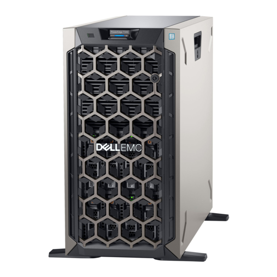
Dell EMC PowerEdge T340 system overview The Dell EMC PowerEdge T340 system is a tower server that supports: • One Intel Xeon Scalable processor • Four DIMM slots • Redundant and cabled AC power supply units • Up to eight 3.5-inch or four 3.5-inch SAS, SATA drives or SSDs... -
Page 10: Front View Of The System
Front view of the system Figure 1. Front view of 8 x 3.5-inch drive system Power button Information tag System health and system ID indicator USB 3.0 port iDRAC direct micro USB port Optical drive (optional) Drive (8) Dell EMC PowerEdge T340 system overview... - Page 11 System health and system ID indicator USB 3.0 port iDRAC direct micro USB port Optical drive (optional) Drive (4) Four-slot drive blank For more information about the ports, see the Ports and connectors specifications section. Dell EMC PowerEdge T340 system overview...
-
Page 12: Rear View Of The System
Power supply unit (PSU 2) USB 2.0 port (4) System Identification button USB 3.0 port (2) iDRAC dedicated NIC port VGA port Serial port NIC port (Gb1) NIC port (Gb2) PCIe expansion card slots (4) Dell EMC PowerEdge T340 system overview... -
Page 13: Inside The System
For more information about the ports and connectors, see the Ports and connectors specifications section. Inside the system NOTE: Components that are hot swappable are marked orange and touch points on the components are marked blue. Dell EMC PowerEdge T340 system overview... - Page 14 Intrusion switch Air shroud Drive backplane Figure 6. Inside the system with redundant power supply unit (PSU) Optical drive or tape drive Power interposer board PCIe Expansion card latch (4) PCIe Expansion card slots (4) Dell EMC PowerEdge T340 system overview...
-
Page 15: Locating The Information Tag Of Your System
Information tag (back view) OpenManage Mobile (OMM) label iDRAC MAC address and iDRAC secure password label Service Tag, Express Service Code, QRL label System information label PowerEdge T340 – System information label Figure 8. Mechanical overview Dell EMC PowerEdge T340 system overview... - Page 16 Figure 9. Electrical overview Figure 10. Icon legend Figure 11. DVD and BOSS installation Figure 12. CPU installation Dell EMC PowerEdge T340 system overview...
- Page 17 Figure 13. Heat sink installation Figure 14. Internal cooling fan installation Figure 15. Memory population Figure 16. Quick resource locator Dell EMC PowerEdge T340 system overview...
-
Page 18: Initial System Setup And Configuration
Initial system setup and configuration Setting up your system Perform the following steps to set up your system: Unpack the system. Connect the peripherals to the system. Connect the system to its electrical outlet. Power on the system by pressing the power button or by using iDRAC. Power on the attached peripherals. -
Page 19: Options To Install The Operating System
Ensure that you change the default user name and password after setting up the iDRAC IP address. NOTE: The Intel Quick Assist Technology (QAT) on the Dell EMC PowerEdge T340 is supported with chipset integration and is enabled through an optional license. The license files are enabled on the sleds through iDRAC. -
Page 20: Downloading Drivers And Firmware
Using iDRAC virtual media Dell.com/idracmanuals Downloading drivers and firmware Dell EMC recommends that you download and install the latest BIOS, drivers, and systems management firmware on your system. Prerequisite Ensure that you clear the web browser cache before downloading the drivers and firmware. -
Page 21: Pre-Operating System Management Applications
Pre-operating system management applications You can manage basic settings and features of a system without booting to the operating system by using the system firmware. Topics: • Options to manage the pre-operating system applications • System Setup • Dell Lifecycle Controller •... -
Page 22: System Setup Details
System Setup details The System Setup Main Menu screen details are explained as follows: Option Description System BIOS Enables you to configure BIOS settings. iDRAC Settings Enables you to configure the iDRAC settings. The iDRAC settings utility is an interface to set up and configure the iDRAC parameters by using UEFI (Unified Extensible Firmware Interface). - Page 23 Option Description Legacy network settings are managed from the Device Settings menu. Integrated Devices Specifies options to manage integrated device controllers and ports, specifies related features and options. Serial Specifies options to manage the serial ports, its related features and options. Communication System Profile Specifies options to change the processor power management settings, memory frequency.
- Page 24 Option Description System Specifies the contact information of the system manufacturer. Manufacturer Contact Information System CPLD Specifies the current version of the system complex programmable logic device (CPLD) firmware. Version UEFI Compliance Specifies the UEFI compliance level of the system firmware. Version Memory Settings You can use the Memory Settings screen to view all the memory settings and enable or disable specific memory functions, such as system...
- Page 25 Option Description Current State of Specifies the current state of the memory operating mode. Memory Operating Mode Processor Settings You can use the Processor Settings screen to view the processor settings, and perform specific functions such as enabling virtualization technology, hardware prefetcher, and logical processor idling. Viewing Processor Settings To view the Processor Settings screen, perform the following steps: Power on, or restart your system.
- Page 26 Option Description Processor 1 The following settings are displayed for each processor installed in the system: Option Description Family-Model- Specifies the family, model, and stepping of the processor as defined by Intel. Stepping Brand Specifies the brand name. Level 2 Cache Specifies the total L2 cache.
- Page 27 Option Description Option Description Drive Type Specifies the type of drive attached to the SATA port. Capacity Specifies the total capacity of the hard drive. This field is undefined for removable media devices such as optical drives. Port B Sets the drive type of the selected device. When the Embedded SATA setting is AHCI Mode, BIOS support is always enabled.
- Page 28 Option Description Option Description Model Specifies the drive model of the selected device. Drive Type Specifies the type of drive attached to the SATA port. Capacity Specifies the total capacity of the hard drive. This field is undefined for removable media devices such as optical drives.
- Page 29 Option Description Hard-Disk Failover Specifies the drive that is booted in the event of a drive failure. The devices are selected in the Hard-Disk Drive Sequence on the Boot Option Setting menu. When this option is set to Disabled, only the first drive in the list is attempted to boot.
- Page 30 UEFI iSCSI Settings You can use the iSCSI Settings screen to modify iSCSI device settings. The iSCSI Settings option is available only in the UEFI boot mode. BIOS does not control network settings in the BIOS boot mode. For the BIOS boot mode, the option ROM of the network controller handles the network settings.
- Page 31 On the System BIOS screen, click Integrated Devices. Integrated Devices details The Integrated Devices screen details are explained as follows: Option Description User Accessible Configures the user accessible USB ports. Selecting Only Back Ports On disables the front USB ports; selecting USB Ports All Ports Off disables all front and back USB ports;...
- Page 32 Option Description Table 3. Slot Disablement Option Description Enables or disables or only the boot driver is disabled Slot 1 for the PCIe slot 1. This option is set to Enabled by default. Enables or disables or only the boot driver is disabled Slot 2 for the PCIe slot 2.
- Page 33 Option Description NOTE: You can use only Serial Device 2 for the Serial Over LAN (SOL) feature. To use console redirection by SOL, configure the same port address for console redirection and the serial device. NOTE: Every time the system boots, the BIOS syncs the serial MUX setting saved in iDRAC. The serial MUX setting can independently be changed in iDRAC.
- Page 34 Option Description NOTE: All the parameters on the system profile setting screen are available only when the System Profile option is set to Custom. CPU Power Sets the CPU power management. This option is set to OS DBPM by default. Management Memory Frequency Sets the speed of the system memory.
- Page 35 On the System BIOS screen, click System Security. System Security Settings details The System Security Settings screen details are explained as follows: Option Description CPU AES-NI Improves the speed of applications by performing encryption and decryption by using the Advanced Encryption Standard Instruction Set (AES-NI).
- Page 36 Option Description In-Band When set to Disabled, this setting will hide the Management Engine's (ME), HECI devices, and the system's IPMI Manageability devices from the operating system. This prevents the operating system from changing the ME power capping Interface settings, and blocks access to all in-band management tools. All management should be managed through out-of- band.
- Page 37 NOTE: If the password jumper setting is disabled, the existing system password and setup password are deleted and you need not provide the system password to boot the system. Steps To enter System Setup, press F2 immediately after turning on or rebooting your system. On the System Setup Main Menu screen, click System BIOS >...
- Page 38 NOTE: If you change the system password or setup password, a message prompts you to reenter the new password. If you delete the system password or setup password, a message prompts you to confirm the deletion. Press Esc to return to the System BIOS screen. Press Esc again, and a message prompts you to save the changes. Select Setup Password, change, or delete the existing setup password and press Enter or Tab.
- Page 39 Redundant OS Control screen details The Redundant OS Control screen details are explained as follows: Option Description Redundant OS Enables you to select a backup disk from the following devices: Location • None • IDSDM • SATA Ports in AHCI mode •...
-
Page 40: Idrac Settings Utility
Option Description System Time Enables you to set the time on the system. System Date Enables you to set the date on the system. Asset Tag Specifies the asset tag and enables you to modify it for security and tracking purposes. Keyboard NumLock Enables you to set whether the system boots with the NumLock enabled or disabled. -
Page 41: Boot Manager
NOTE: Certain platform configurations may not support the full set of features provided by the Dell Lifecycle Controller. For more information about setting up the Dell Lifecycle Controller, configuring hardware and firmware, and deploying the operating system, see the Dell Lifecycle Controller documentation at Dell.com/poweredgemanuals. Boot Manager The Boot Manager screen enables you to select boot options and diagnostic utilities. -
Page 42: Pxe Boot
PXE boot You can use the Preboot Execution Environment (PXE) option to boot and configure the networked systems, remotely. To access the PXE boot option, boot the system and then press F12 during POST instead of using standard Boot Sequence from BIOS Setup. -
Page 43: Installing And Removing System Components
Installing and removing system components Safety instructions WARNING: Whenever you need to lift the system, get others to assist you. To avoid injury, do not attempt to lift the system by yourself. WARNING: Opening or removing the system cover while the system is powered on may expose you to a risk of electric shock. CAUTION: Do not operate the system without the cover for a duration exceeding five minutes. -
Page 44: Front Bezel
• Phillips #1 screwdriver • Phillips #2 screwdriver • 5mm hex nut screwdriver • Plastic scribe • Wrist grounding strap connected to the ground • ESD mat Front bezel Removing the front bezel Prerequisites Follow the safety guidelines listed in Safety instructions. -
Page 45: Installing The Front Bezel
Installing the front bezel Prerequisites Follow the safety guidelines listed in Safety instructions. Locate and remove the bezel key. NOTE: The bezel key is part of the bezel package. Steps Align and insert the bezel tabs into the slots in the system. Press the release latch, and push the bezel toward the system until the bezel locks into place. -
Page 46: Installing The System Feet
Steps Using the Phillips #2 screwdriver, remove the screw that secures the foot to the base of the system. Repeat the preceding step to remove the remaining system feet. Figure 19. Removing the system feet Next step Replace the system feet install the caster wheels. -
Page 47: Caster Wheels - Optional
Figure 20. Installing the system feet Next steps Place the system upright on a flat, stable surface, and rotate the system feet outward. Follow the procedure listed in After working inside your system. Caster wheels – optional Removing caster wheels Prerequisites Follow the safety guidelines listed in Safety... -
Page 48: Installing Caster Wheels
Next step Replace the caster wheels replace the system feet, as applicable. Installing caster wheels Prerequisites Follow the safety guidelines listed in Safety instructions. Place the system on its side on a flat, stable surface. If installed, remove the system feet. -
Page 49: System Cover
Figure 21. Installing caster wheels Next step Follow the procedure listed in After working inside your system. System cover Removing the system cover Prerequisites Follow the safety guidelines listed in Safety instructions. Power off the system and all attached peripherals. Disconnect the system from the electrical outlet and disconnect the peripherals. -
Page 50: Installing The System Cover
Figure 22. Removing the system cover Installing the system cover Prerequisites Follow the safety guidelines listed in Safety instructions. Remove the front bezel. Power off the system and all attached peripherals. Disconnect the system from the electrical outlet and disconnect the peripherals. Ensure that all internal cables are connected and placed out of the way and no tools or extra parts are left inside the system. -
Page 51: Air Shroud
Figure 23. Installing the system cover Next steps Place the system upright on its feet on a flat, stable surface. Install the front bezel. Reconnect the peripherals, and connect the system to the electrical outlet. Power on the system and all attached peripherals. Air shroud Removing the air shroud Prerequisites... -
Page 52: Installing The Air Shroud
Figure 24. Removing the air shroud Next step Replace the air shroud. Installing the air shroud Prerequisites Follow the safety guidelines listed in Safety instructions. Follow the procedure listed in Before working inside your system. If applicable, route the cables inside the system along the system wall and secure the cables by using the cable-securing bracket. Steps Align the tabs on the air shroud with the slots on the system. -
Page 53: Intrusion Switch
Figure 25. Installing the air shroud Next steps Install the system cover. Follow the procedure listed in Before working inside your system. Intrusion switch Removing the intrusion switch Prerequisites Follow the safety guidelines listed in Safety instructions. Follow the procedure listed in Before working inside your system. -
Page 54: Installing The Intrusion Switch
Figure 26. Removing the intrusion switch Next step Replace the intrusion switch. Installing the intrusion switch Prerequisites Follow the safety guidelines listed in Safety instructions. Follow the procedure listed in Before working inside your system. Steps Align and slide the intrusion switch into the slot in the system. Connect the intrusion switch cable connector to the intrusion switch connector on the system board. -
Page 55: Drives
Figure 27. Installing the intrusion switch Next steps Install the air shroud. Follow the procedure that is listed in After working inside your system. Drives Removing a drive blank Prerequisites Follow the safety guidelines listed in Safety instructions. Follow the procedure listed in Before working inside your system. -
Page 56: Installing A Drive Blank
Figure 28. Removing a drive blank NOTE: The procedure to remove a 2.5-inch or a 3.5-inch drive blank is the same. Next step Replace the drive or a drive blank. Installing a drive blank Prerequisites Follow the safety guidelines listed in Safety instructions. -
Page 57: Removing A Drive Carrier
Removing a drive carrier Prerequisites Follow the safety guidelines listed in Safety instructions. Remove the front bezel. Using the management software, prepare the drive for removal. If the drive is online, the green activity or fault indicator flashes while the drive is turning off. When the drive indicators are off, the drive is ready for removal. -
Page 58: Installing The Drive Carrier
Installing the drive carrier Prerequisites CAUTION: Before removing or installing a drive while the system is running, see the documentation for the storage controller card to ensure that the host adapter is configured correctly to support drive removal and insertion. CAUTION: Combining SAS and SATA drives in the same RAID volume is not supported. -
Page 59: Removing The Drive From The Drive Carrier
Next steps Install the front bezel. Follow the procedure listed in After working inside your system. Removing the drive from the drive carrier Prerequisites Follow the safety guidelines listed in Safety instructions. CAUTION: Mixing drive carriers from previous generations of PowerEdge servers is not supported. Follow the procedure listed in Before working inside your system. -
Page 60: Removing A 2.5-Inch Drive From The 3.5-Inch Drive Adapter
CAUTION: Mixing drive carriers from other generations of PowerEdge servers is not supported. Steps Insert the drive into the drive carrier with the connector end of the drive towards the back of the carrier. Align the screw holes on the drive with the screws holes on the drive carrier. When aligned correctly, the back of the drive is flush with the back of the drive carrier. -
Page 61: Installing A 2.5-Inch Drive Into The 3.5-Inch Drive Adapter
Figure 34. Removing a 2.5-inch drive from the 3.5-inch drive adapter Next step Replace a 2.5-inch drive into the 3.5-inch drive adapter. Installing a 2.5-inch drive into the 3.5-inch drive adapter Prerequisite Follow the safety guidelines listed in Safety instructions. Steps Align the screw holes on the 2.5-inch drive with the screw holes on the 3.5-inch drive adapter. -
Page 62: Removing A 3.5-Inch Drive Adapter From A 3.5-Inch Drive Carrier
Figure 35. Installing a 2.5-inch drive into the 3.5-inch drive adapter Next steps Replace a 3.5-inch adapter into the 3.5-inch drive carrier. Follow the procedure listed in After working inside your system. Removing a 3.5-inch drive adapter from a 3.5-inch drive carrier Prerequisites Follow the safety guidelines listed in Safety... -
Page 63: Installing A 3.5-Inch Adapter Into A 3.5-Inch Drive Carrier
Figure 36. Removing a 3.5-inch drive adapter from a 3.5-inch drive carrier Next step Replace a 3.5-inch adapter into a 3.5-inch drive carrier. Installing a 3.5-inch adapter into a 3.5-inch drive carrier Prerequisite Follow the safety guidelines listed in Safety instructions. -
Page 64: Optical Drive And Tape Drives
Figure 37. Installing a 3.5-inch drive adapter into the 3.5-inch drive carrier Next steps Replace a 3.5-inch drive carrier into the system. Follow the procedure listed in After working inside your system. Optical drive and tape drives Removing the optical or tape drive blank Prerequisites NOTE: The procedure to remove the optical drive blank is identical to removing a tape drive blank. -
Page 65: Installing The Optical Or Tape Drive Blank
Figure 38. Removing the optical drive or tape drive blank NOTE: Blanks must be installed on empty optical drive or tape drive slots to maintain FCC certification of the system. The brackets also keep dust and dirt out of the system and aid in proper cooling and airflow inside the system. Perform the same steps to install blanks. -
Page 66: Removing The Optical Drive
Figure 39. Installing the optical or tape drive blank Next steps Install the front bezel. Follow the procedure listed in After working inside your system. Removing the optical drive Prerequisites Follow the safety guidelines listed in Safety instructions. Follow the procedure listed in Before working inside your system. -
Page 67: Installing The Optical Drive
Figure 40. Removing the optical drive Next steps Replace the optical drive. Follow the procedure listed in After working inside your system. Installing the optical drive Prerequisites Ensure that you follow the procedure listed in Safety instructions. Follow the procedure listed in Before working inside your system. -
Page 68: Removing The Tape Drive
Figure 41. Installing the optical drive Next steps Install the front bezel. Follow the procedure listed in After working inside your system. Removing the tape drive Prerequisites Follow the safety guidelines listed in Safety instructions. Follow the procedure listed in Before working inside your system. -
Page 69: Installing The Tape Drive
Figure 42. Removing the tape drive Next steps Replace the tape drive. Follow the procedure listed in After working inside your system. Installing the tape drive Prerequisites Ensure that you follow the procedure listed in Safety instructions. Follow the procedure listed in Before working inside your system. -
Page 70: Drive Backplane
Figure 43. Installing the tape drive Next steps Install the front bezel. Follow the procedure listed in After working inside your system. Drive backplane Drive backplane details Your system supports the following backplane configuration: • x8 SAS/SATA backplane for 3.5-inch drives NOTE: The x8 backplane also supports up to eight 2.5-inch (SAS, SATA, or SSD) hot swappable drives that can be installed in 3.5-inch drive adapters, which can be installed in the 3.5-inch drive carriers. -
Page 71: Removing The Drive Backplane
Figure 44. x8 SAS/SATA backplane for 3.5-inch drives ODD power connector (P1) Backplane P4 power connector (BP_PWR) Backplane sideband signal connector (BP_SIG) Mini SAS SAS_A0 Mini SAS SAS_B0 Removing the drive backplane Prerequisites CAUTION: Note the number of each drive and temporarily label them before you remove the drive so that you can replace them in the same location. -
Page 72: Installing The Drive Backplane
Figure 45. Removing the drive backplane Next steps Replace a drive backplane. Follow the procedure listed in After working inside your system. Installing the drive backplane Prerequisites Follow the safety guidelines listed in Safety instructions. Follow the procedure listed in Before working inside your system. -
Page 73: Backplane Cable Routing
Figure 46. Installing the drive backplane Next steps Install the air shroud. Install the drives. Install the front bezel. Follow the procedure listed in After working inside your system. Backplane cable routing Figure 47. Cable routing - 8 x 3.5-inch, SATA drive backplane Installing and removing system components... -
Page 74: Four-Slot Drive Blank
Figure 48. Cable routing - 8 x 3.5-inch SAS/SATA drive backplane with PERC card Four-slot drive blank Systems with x8 drive backplanes configured for software RAID support only four drives. The remaining drive slots are pre-installed with the four-slot drive blank, and cannot be upgraded for additional storage. Removing a four-slot drive blank Prerequisites CAUTION:... -
Page 75: Installing A Four-Slot Drive Blank
Figure 49. Removing a four-slot drive blank Next step Replace a four-slot drive blank. Installing a four-slot drive blank Prerequisites Follow the safety guidelines listed in Safety instructions. Follow the procedure listed in Before working inside your system. Steps Locate the drive slots numbered from four to seven. Insert the four-slot drive blank into the drive slot, and push it until the release tabs click into place. -
Page 76: System Memory
Figure 50. Installing a four-slot drive blank Next steps Install the drive backplane. Install the drives. Install the air shroud. Follow the procedure listed in After working inside your system. System memory System memory guidelines The system supports DDR4 unbuffered DIMMs (UDIMMs). System memory holds the instructions that are executed by the processor. Your system contains 4 memory sockets. - Page 77 Figure 51. System memory view Table 4. Memory channels Processor Channel 0 Channel 1 Processor 1 Slots A1, A3 Slots A2, A4 The following table shows the memory populations and operating frequencies for the supported configurations: Table 5. Memory population DIMM Type DIMMs Populated/ Operating Frequency (in...
-
Page 78: General Memory Module Installation Guidelines
General memory module installation guidelines To ensure optimal performance of your system, observe the following general guidelines when configuring your system memory. If your system's memory configurations fail to observe these guidelines, your system might not boot, stop responding during memory configuration, or operate with reduced memory. -
Page 79: Installing A Memory Module
Follow the procedure listed in Before working inside your system. Remove the air shroud. Steps Locate the appropriate memory module socket. CAUTION: Handle each memory module only by the edges, ensuring not to touch the middle of the memory module or metallic contacts. -
Page 80: Cooling Fan
NOTE: The memory module socket has an alignment key that enables you to install the memory module in the socket in only one orientation. Press the memory module with your thumbs until the ejectors firmly click into place. Figure 53. Installing a memory module Next steps Install the air shroud. -
Page 81: Installing The Internal Cooling Fan
Figure 54. Removing the internal cooling fan CAUTION: Do not remove or install the fan by holding the fan blades. Next step Replace the internal fan. Installing the internal cooling fan Prerequisites Follow the safety guidelines listed in Safety instructions. Follow the procedure listed in Before working inside your system. -
Page 82: Optional Internal Usb Memory Key
Figure 55. Installing the internal cooling fan Next steps Install the air shroud. Follow the procedure listed in After working inside your system. Optional internal USB memory key An optional USB memory key installed inside your system can be used as a boot device, security key, or mass storage device. To boot from the USB memory key, configure the USB memory key with a boot image and then specify the USB memory key in the boot sequence in System Setup. -
Page 83: Expansion Cards
Troubleshooting expansion cards section in system from turning on. However, if a F1/F2 pause occurs with an error message, see Dell EMC PowerEdge Servers Troubleshooting Guide at Dell.com/poweredgemanuals. Expansion card guidelines The following table describes the installation order for installing expansion cards to ensure proper cooling and mechanical fit. The expansion cards with the highest priority must be installed first by using the slot priority indicated. -
Page 84: Removing An Expansion Card
Card Category Card Type Form Factor Slot Priority Maximum Priority Allowed 1 Gb NICs Dual Port (Broadcom) Full Height 1,2,3,4 1 Gb NICs Quad Port (Intel) Full Height 1,2,4 Removing an expansion card Prerequisites Follow the safety guidelines listed in Safety instructions. -
Page 85: Installing An Expansion Card
Figure 57. Removing the filler bracket Hold the expansion card by its edges, and pull the card up to remove it from the expansion card connector and the system. Install the filler bracket by performing the following steps: Align the expansion card filler bracket with the slot on the system. b Push the expansion card filler bracket downwards until firmly seated. - Page 86 Figure 58. Installing an expansion card Figure 59. Installing the filler bracket Connect the data cables to the expansion card. Next steps Install the air shroud. Connect the cables to the expansion card. Follow the procedure listed in After working inside your system.
-
Page 87: M.2 Ssd Module
M.2 SSD module Removing the M.2 SSD module Prerequisites Follow the safety guidelines listed in Safety instructions. Follow the procedure listed in Before working inside your system. Remove the air shroud. Remove the BOSS card. NOTE: The procedure to remove the BOSS card is similar to removing an expansion card. Steps Using the Phillips #1 screwdriver, remove the screws securing the M.2 SSD module to the BOSS card. -
Page 88: Optional Idsdm Or Vflash Module
Remove the BOSS card. NOTE: The procedure to remove the BOSS card is similar to the removing an expansion card. Steps Align the M.2 SSD module at an angle with the BOSS card connector. Insert the M.2 SSD module until it is firmly seated in the BOSS card connector. Using the Phillips #1 screwdriver, secure the M.2 SSD module on the BOSS card with the screw. -
Page 89: Installing Optional Idsdm Or Vflash Card
If you are replacing the IDSDM/vFlash card, remove the MicroSD cards. NOTE: Temporarily label each SD card with its corresponding slot number before removal. Reinstall the SD cards into the corresponding slots. Step Holding the pull tab, lift the IDSDM/vFlash card out of the system. Next step NOTE: If you are replacing the IDSDM or vFlash module, remove the MicroSD cards. -
Page 90: Removing The Microsd Card
Follow the procedure that is listed in After working inside your system. Removing the MicroSD card Prerequisites Follow the safety guidelines listed in the Safety instructions. Follow the procedure listed in the Before working inside your system. Remove the air shroud. Remove the IDSDM or vFlash module. -
Page 91: Processor And Heat Sink
Follow the procedure listed in the Before working inside your system. Remove the air shroud. Remove the IDSDM or vFlash module. NOTE: To use a MicroSD card with your system, ensure that the Internal SD Card Port is enabled in System Setup. NOTE: If reinstalling, ensure that you install the MicroSD cards into the same slots based on the labels you had marked on the cards during removal. - Page 92 Follow the safety guidelines listed in Safety instructions. Follow the procedure listed in Before working inside your system. Remove the air shroud Steps Using a Phillips #2 screwdriver, loosen the screws on the heat sink in the order below: Loosen the first screw three turns. b Loosen the second screw completely.
-
Page 93: Removing The Processor
Removing the processor Prerequisites WARNING: The heat sink may be hot to touch for some time after the system has been powered down. Allow the heat sink to cool before removing it. Follow the safety guidelines listed in Safety instructions. Follow the procedure listed in Before working inside your system. -
Page 94: Installing The Heat Sink
Figure 67. Installing the processor Next steps Replace the heat sink. Replace the air shroud. Follow the procedure listed in After working inside your system. Installing the heat sink Prerequisites Follow the safety guidelines listed in Safety instructions. Follow the procedure listed in Before working inside your system. - Page 95 Figure 68. Applying thermal grease on top of the processor CAUTION: Applying too much thermal grease can result in excess grease coming in contact with and contaminating the processor socket. NOTE: The thermal grease syringe is intended for one-time use only. Dispose of the syringe after you use it. Align the screws on the heat sink with the standoffs on the system board.
-
Page 96: Power Supply Unit
Figure 69. Installing the heat sink Next steps Replace the air shroud. Follow the procedure listed in After working inside your system. While booting, press F2 to enter System Setup and verify that the processor information matches the new system configuration. Run the system diagnostics to verify that the new processor operates correctly. -
Page 97: Installing The Power Supply Unit Blank
CAUTION: To ensure proper system cooling, the PSU blank must be installed in the second PSU bay in a non-redundant configuration. Remove the PSU blank only if you are installing a second PSU. Figure 70. Removing the power supply unit blank Next step Install the PSU PSU blank. -
Page 98: Removing A Redundant Ac Power Supply Unit
Figure 71. Installing the power supply unit blank Removing a redundant AC power supply unit Prerequisites Follow the safety guidelines listed in Safety instructions. Disconnect the power cable from the power outlet and from the PSU you want to remove, then remove the cable from the strap on the PSU handle. -
Page 99: Installing A Redundant Ac Power Supply Unit
Figure 72. Removing a redundant power supply unit Next step Install the PSU PSU blank. Installing a redundant AC power supply unit Prerequisites Follow the safety guidelines listed in Safety instructions. For systems that support redundant PSU, ensure that both the PSUs are of the same type and have the same maximum output power. -
Page 100: Removing A Cabled Power Supply Unit
Figure 73. Installing a redundant power supply unit Next step Connect the power cable to the PSU, and plug the cable into a power outlet. CAUTION: When connecting the power cable to the PSU, secure the cable to the PSU with the strap. NOTE: When installing, hot swapping, or hot adding a new PSU, wait for 15 seconds for the system to recognize the PSU and determine its status. -
Page 101: Installing A Cabled Power Supply Unit
Figure 74. Removing a cabled power supply unit Next step Replace a cabled PSU. Installing a cabled power supply unit Prerequisites Follow the safety guidelines listed in Safety instructions. Unpack the replacement power supply unit (PSU). Steps Slide the PSU into the PSU bay in the chassis until the PSU is fully seated. Tighten the screw to secure the PSU to the system. -
Page 102: Power Interposer Board
Figure 75. Installing a cabled power supply unit Next step Follow the procedure listed in After working inside your system. Power interposer board Removing the power interposer board Prerequisites Follow the safety guidelines listed in Safety instructions. Follow the procedure listed in Before working inside your system. -
Page 103: Installing The Power Interposer Board
Figure 76. Removing the power interposer board Next step Replace the power interposer board (PIB). Installing the power interposer board Prerequisites Follow the safety guidelines listed in Safety instructions. Follow the procedure listed in Before working inside your system. Remove the power supply units. Remove the air shroud. -
Page 104: System Battery
Next steps Install the air shroud Replace the PSUs. Follow the procedure that is listed in After working inside your system. System battery Replacing the system battery Prerequisites WARNING: There is a danger of a new battery exploding if it is incorrectly installed. Replace the battery only with the same or equivalent type that the manufacturer recommends. -
Page 105: System Board
Figure 79. Installing the system battery Next steps Follow the procedure listed in After working inside your system. Enter the System Setup to confirm that the battery is operating properly. Enter the correct time and date in the System Setup's Time and Date fields. Exit the System Setup. - Page 106 vFlash/IDSDM module Internal USB key, if installed Processors and heat sink CAUTION: To prevent damage to the processor pins when replacing a faulty system board, ensure that you cover the processor socket with the processor protective cap. Memory modules Steps Disconnect all cables from the system board.
-
Page 107: Installing The System Board
Next step Replace or install the system board. Installing the system board Prerequisite Follow the safety guidelines listed in Safety instructions. Steps Unpack the new system board assembly. CAUTION: Do not lift the system board by holding a memory module, processor, or other components. CAUTION: Take care not to damage the system identification button while placing the system board into the system. - Page 108 Next steps Replace the following: Trusted Platform Module (TPM) NOTE: The TPM plug-in module is attached to the system board and cannot be removed. A replacement TPM plug-in module is provided for all system board replacements, where a TPM plug-in module was installed. Memory modules Processors and heat sink Internal USB...
-
Page 109: Trusted Platform Module
Steps Power on the system. To enter the System Setup, press F2. Click Service Tag Settings. Enter the service tag. NOTE: You can enter the service tag only when the Service Tag field is empty. Ensure that you enter the correct service tag. -
Page 110: Initializing Tpm For Bitlocker Users
Figure 83. Installing the TPM Next steps Replace the system board. Follow the procedure listed in After working inside your system. To verify if the memory module has been installed properly, press F2 and navigate to System Setup Main Menu > System BIOS > Memory Settings. -
Page 111: Control Panel
From the TPM Security option, select On. Save the settings. Restart your system. Enter System Setup again. On the System Setup Main Menu screen, click System BIOS > System Security Settings. Select the TPM Advanced Settings option. From the TPM2 Algorithm Selection option, select SHA256, then go back to System Security Settings screen. On the System Security Settings screen, from the Intel TXT option, select On. -
Page 112: Installing The Control Panel Assembly
NOTE: Retain the information tag to replace it in the new control panel. Next step Replace the control panel assembly. Installing the control panel assembly Prerequisite Follow the safety guidelines listed in Safety instructions. Steps Replace the blank information tag in the new control panel with the information tag retained from the old control panel. To install the information tag, push the information tag into the control-panel slot. -
Page 113: Jumpers And Connectors
Jumpers and connectors This topic provides specific information about the jumpers. It also provides some basic information about jumpers and switches and describes the connectors on the various boards in the system. Jumpers on the system board help to disable the system and setup passwords. -
Page 114: System Board Jumpers And Connectors
System board jumpers and connectors Figure 86. T340 system board jumpers and connectors Table 9. System board connectors Item Connector Description FP_USB Front panel USB connector PIB_CONN Power interposer board signal connector BP_SIG Backplane signal connector Slot 1 PCIE_G3_X8 CPU PCIe card connector 1 Slot 2 PCIE_G3_X8 CPU PCIe card connector 2... -
Page 115: System Board Jumper Settings
Item Connector Description INT_USB_3.0 Internal USB Slot 4 PCIE_G3_X4 PCH PCIe card connector 4 T_INTRUSION Intrusion switch connector SYS_FAN CPU power connector P2 A1, A2, A3, A4 Memory module sockets System power P1 SATA 0-3 Mini SAS connector SATA_ODD/SSD Optical disk drive connector PWR_EVNT Power event J_SATA_2... -
Page 116: Disabling Forgotten Password
Disabling forgotten password The software security features of the system include a system password and a setup password. The password jumper enables or disables password features and clears any password(s) currently in use. Prerequisite CAUTION: Many repairs may only be done by a certified service technician. You should only perform troubleshooting and simple repairs as authorized in your product documentation, or as directed by the online or telephone service and support team. -
Page 117: Technical Specifications
Technical specifications The technical and environmental specifications of your system are outlined in this section. Topics: • Chassis dimensions • System weight • Processor specifications • Supported operating systems • PSU specifications • Cooling fan specifications • System battery specifications •... -
Page 118: Chassis Dimensions
(17.45 inches) (18.56 inches) (21.47 inches) (23.19 inches) inches) System weight Table 12. Dell EMC PowerEdge T340 system chassis weight System configuration Maximum weight (with all drives/SSDs) 8 x 3.5-inch drives 25.25 Kg (55.67 lb) Processor specifications Table 13. Dell EMC PowerEdge T340 processor specifications... -
Page 119: Supported Operating Systems
For more information about the specific versions and additions, go to https://www.dell.com/support/home/Drivers/ SupportedOS/poweredge-t340. PSU specifications The Dell EMC PowerEdge T340 system supports up to two AC power supply units (PSUs). Table 14. Dell EMC PowerEdge T340 PSU specifications Class Heat... -
Page 120: Memory Specifications
Half Length x4 link in x8 slot NOTE: The expansion cards are not hot swappable. Memory specifications The Dell EMC PowerEdge T340 system supports the following memory specifications for optimized operation: Table 16. Memory specifications DIMM type DIMM rank DIMM capacity... -
Page 121: Optical Drives
The Dell EMC PowerEdge T340 system supports up to two 10/100/1000 Mbps Network Interface Controller (NIC) ports that are located on the back panel. Serial connector specifications The Dell EMC PowerEdge T340 system supports one serial connector on the back panel, which is a 9-pin connector, Data Terminal Equipment (DTE), 16550-compliant. VGA ports specification The Dell EMC PowerEdge T340 system supports two 15-pin VGA ports, one each, on the front and back of the system. -
Page 122: Idsdm Module
One IDSDM card slot is dedicated for redundancy. NOTE: Use Dell EMC branded microSD cards that are associated with the IDSDM or vFlash configured systems. Video specifications The Dell EMC PowerEdge T340 system supports Matrox G200eR2 graphics card with 16 MB capacity. - Page 123 Temperature Specifications Fresh air For information about fresh air, see the Expanded operating temperature section. Maximum temperature gradient (operating and 20°C/h (36°F/h) storage) Table 23. Relative humidity specifications Relative humidity Specifications Storage 5% to 95% RH with 33°C (91°F) maximum dew point. Atmosphere must be noncondensing at all times.
-
Page 124: Standard Operating Temperature
Standard operating temperature Table 28. Standard operating temperature specifications Standard operating temperature Specifications Continuous operation (for altitude less than 950 m or 3117 10–35°C (50–95°F) with no direct sunlight on the equipment. Expanded operating temperature Table 29. Expanded operating temperature specifications Expanded operating temperature Specifications Continuous operation... -
Page 125: Particulate And Gaseous Contamination Specifications
• Tape backup unit is supported. Particulate and gaseous contamination specifications The following table defines the limitations that help avoid any damages to the IT equipment and/or, or both failure from particulate and gaseous contamination. If the levels of particulate or gaseous pollution exceed the specified limitations and results in equipment damage or failure, you must rectify the environmental conditions. -
Page 126: System Diagnostics And Indicator Codes
System diagnostics and indicator codes The diagnostic indicators on the system front panel display system status during system startup. Topics: • System health and system ID indicator codes • iDRAC Direct LED indicator codes • NIC indicator codes • Non-redundant cabled power supply unit indicator codes •... -
Page 127: Nic Indicator Codes
Table 33. iDRAC Direct LED indicator codes iDRAC Direct LED Condition indicator code Solid green for two seconds Indicates that the laptop or tablet is connected. Flashing green (on for two Indicates that the laptop or tablet connected is recognized. seconds and off for two seconds) Powers off... -
Page 128: Power Supply Unit Indicator Codes
Figure 90. Non-redundant cabled AC PSU status indicator and self-diagnostic button Self-diagnostic button AC PSU status indicator Table 35. Non-redundant AC PSU status indicator Power Indicator Pattern Condition Not lit Power is not connected or PSU is faulty. Green A valid power source is connected to the PSU and the PSU is operational. Power supply unit indicator codes AC power supply units (PSUs) have an illuminated translucent handle that serves as an indicator. -
Page 129: Drive Indicator Codes
Power indicator codes Condition CAUTION: Do not disconnect the power cord or unplug the PSU when updating firmware. If firmware update is interrupted, the PSUs do not function. Blinking green and turns off When hot-plugging a PSU, the PSU handle blinks green five times at a rate of 4 Hz and turns off. This indicates a PSU mismatch with respect to efficiency, feature set, health status, or supported voltage. -
Page 130: Using System Diagnostics
Table 37. Drive indicator codes Drive status indicator code Condition Flashes green twice per second Identifying drive or preparing for removal. Drive ready for removal. NOTE: The drive status indicator remains off until all drives are initialized after the system is turned on. Drives are not ready for removal during this time. - Page 131 Running the Embedded System Diagnostics from the Dell Lifecycle Controller As the system boots, press F10. Select Hardware Diagnostics → Run Hardware Diagnostics. The ePSA Pre-boot System Assessment window is displayed, listing all devices detected in the system. The diagnostics starts executing the tests on all the detected devices.
-
Page 132: Getting Help
Accessing system information by using QRL You can use the Quick Resource Locator (QRL) located on the information tag in the front of the T340, to access the information about the Dell EMC PowerEdge T340. Prerequisites Ensure that your smartphone or tablet has the QR code scanner installed. -
Page 133: Quick Resource Locator For Dell Emc Poweredge T340 System
Receiving automated support with SupportAssist Dell EMC SupportAssist is an optional Dell EMC Services offering that automates technical support for your Dell EMC server, storage, and networking devices. By installing and setting up a SupportAssist application in your IT environment, you can receive the following benefits: •... -
Page 134: Documentation Resources
To view the document that is listed in the documentation resources table: • From the Dell EMC support site: Click the documentation link that is provided in the Location column in the table. Click the required product or product version. - Page 135 Dell OpenManage Essentials, see Essentials the Dell OpenManage Essentials User’s Guide. For information about installing and using Dell Dell.com/serviceabilitytools SupportAssist, see the Dell EMC SupportAssist Enterprise User’s Guide. For information about partner programs enterprise Dell.com/openmanagemanuals systems management, see the OpenManage Connections Enterprise Systems Management documents.
Need help?
Do you have a question about the PowerEdge T340 DPJ1G and is the answer not in the manual?
Questions and answers