
Related Manuals for Dell EMC PowerEdge T340


Summary of Contents for Dell EMC PowerEdge T340
- Page 1 Dell EMC PowerEdge T340 Installation and Service Manual Regulatory Model: E60S Regulatory Type: E60S001 Dec 2020 Rev. A07...
- Page 2 Notes, cautions, and warnings NOTE: A NOTE indicates important information that helps you make better use of your product. CAUTION: A CAUTION indicates either potential damage to hardware or loss of data and tells you how to avoid the problem. WARNING: A WARNING indicates a potential for property damage, personal injury, or death.
-
Page 3: Table Of Contents
Contents Chapter 1: About this document....................6 Chapter 2: Dell EMC PowerEdge T340 system overview..............7 Front view of the system..............................8 Rear view of the system..............................10 Inside the system................................11 Locating the information tag of your system......................13 System information label..............................13 Chapter 3: Initial system setup and configuration................ - Page 4 Removing a drive carrier............................33 Installing the drive carrier............................34 Removing the drive from the drive carrier......................35 Installing the drive into the drive carrier........................36 Removing a 2.5-inch drive from the 3.5-inch drive adapter................37 Installing a 2.5-inch drive into the 3.5-inch drive adapter................38 Removing a 3.5-inch drive adapter from a 3.5-inch drive carrier..............
- Page 5 Chapter 7: Getting help....................... 96 Recycling or End-of-Life service information......................96 Contacting Dell.................................. 96 Accessing system information by using QRL......................96 Quick Resource Locator for Dell EMC PowerEdge T340 system..............97 Receiving automated support with SupportAssist ....................97 Chapter 8: Documentation resources...................98 Contents...
-
Page 6: Chapter 1: About This Document
About this document This document provides an overview about the system, information about installing and replacing components, technical specifications, diagnostic tools, and guidelines to be followed while installing certain components. About this document... -
Page 7: Chapter 2: Dell Emc Poweredge T340 System Overview
Dell EMC PowerEdge T340 system overview The Dell EMC PowerEdge T340 system is a tower server that supports: ● One Intel Xeon, Core i3, Pentium, or Celeron processor ● Four DIMM slots ● Redundant and cabled AC power supply units ●... -
Page 8: Front View Of The System
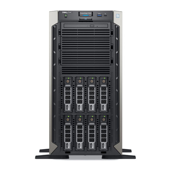
Figure 1. Front view of 8 x 3.5-inch drive system 1. Power button 2. Information tag 3. System health and system ID indicator 4. USB 3.0 port 5. iDRAC direct micro USB port 6. Optical drive (optional) 7. Drive (8) Dell EMC PowerEdge T340 system overview... - Page 9 4. USB 3.0 port 5. iDRAC direct micro USB port 6. Optical drive (optional) 7. Drive (4) 8. Four-slot drive blank For more information about the ports, see the Dell EMC PowerEdge T340 Technical Specifications Guide. Dell EMC PowerEdge T340 system overview...
-
Page 10: Rear View Of The System
4. System Identification button 5. USB 3.0 port (2) 6. iDRAC dedicated NIC port 7. VGA port 8. Serial port 9. NIC port (Gb1) 10. NIC port (Gb2) 11. PCIe expansion card slots (4) Dell EMC PowerEdge T340 system overview... -
Page 11: Inside The System
8. NIC port (Gb1) 9. NIC port (Gb2) 10. PCIe expansion card slots (4) NOTE: For more information about the ports and connectors, see the Dell EMC PowerEdge T340 Technical Specifications Guide. Inside the system NOTE: Components that are hot swappable are marked orange and touch points on the components are marked blue. - Page 12 2. Power interposer board 3. PCIe Expansion card latch (4) 4. PCIe Expansion card slots (4) 5. Intrusion switch 6. Fan 7. Memory module socket (4) 8. Processor and heat sink 9. System board 10. Drive backplane Dell EMC PowerEdge T340 system overview...
-
Page 13: Locating The Information Tag Of Your System
3. OpenManage Mobile (OMM) label 4. iDRAC MAC address and iDRAC secure password label 5. Service Tag, Express Service Code, QRL label System information label PowerEdge T340 – System information label Figure 8. Mechanical overview Dell EMC PowerEdge T340 system overview... - Page 14 Figure 9. Electrical overview Figure 10. Icon legend Figure 11. DVD and BOSS installation Figure 12. CPU installation Dell EMC PowerEdge T340 system overview...
- Page 15 Figure 13. Heat sink installation Figure 14. Internal cooling fan installation Figure 15. Memory population Figure 16. Quick resource locator Dell EMC PowerEdge T340 system overview...
-
Page 16: Chapter 3: Initial System Setup And Configuration
Initial system setup and configuration Topics: • Setting up your system • iDRAC configuration • Options to install the operating system Setting up your system Perform the following steps to set up your system: Steps 1. Unpack the system. 2. Connect the peripherals to the system. 3. -
Page 17: Log In To Idrac
Deployment Toolkit Dell certified VMware ESXi www.dell.com/virtualizationsolutions Installation and How-to videos for supported operating Supported Operating Systems for Dell EMC PowerEdge systems on PowerEdge systems systems Methods to download firmware and drivers You can download the firmware and drivers by using any of the following methods: Table 2. -
Page 18: Downloading Drivers And Firmware
Using iDRAC virtual media www.dell.com/idracmanuals Downloading drivers and firmware Dell EMC recommends that you download and install the latest BIOS, drivers, and systems management firmware on your system. Prerequisites Ensure that you clear the web browser cache before downloading the drivers and firmware. -
Page 19: Chapter 4: Installing And Removing System Components
Installing and removing system components Topics: • Safety instructions • Before working inside your system • After working inside your system • Recommended tools • Front bezel • System feet • Caster wheels – optional • System cover • Air shroud •... -
Page 20: Before Working Inside Your System
NOTE: It is recommended that you always use an antistatic mat and antistatic strap while working on components inside the system. Before working inside your system Prerequisites Follow the safety guidelines listed in Safety instructions. Steps 1. Power off the system and all attached peripherals. 2. -
Page 21: Installing The Front Bezel
2. Press the blue release latch at the top of the bezel to release the bezel from the system. 3. Unhook the bezel tabs from the slots at the bottom, and lift the bezel. Figure 17. Removing the front bezel Next steps Replace the front bezel. -
Page 22: System Feet
Figure 18. Installing the front bezel System feet Removing the system feet Prerequisites NOTE: It is recommended that you remove the system feet only when you are replacing the system feet with the wheel assembly. 1. Follow the safety guidelines listed in Safety instructions.. -
Page 23: Installing The System Feet
Figure 19. Removing the system feet Next steps Replace the system feet install the caster wheels. Installing the system feet Prerequisites CAUTION: Install the feet on a stand-alone tower system to provide stability to the system. An unstable system might tip over and cause injury to the user or damage to the system. 1. -
Page 24: Caster Wheels - Optional
Figure 20. Installing the system feet Next steps 1. Place the system upright on a flat, stable surface, and rotate the system feet outward. 2. Follow the procedure listed in After working inside your system. Caster wheels – optional Removing caster wheels Prerequisites 1. -
Page 25: Installing Caster Wheels
Next steps Replace the caster wheels replace the system feet, as applicable. Installing caster wheels Prerequisites 1. Follow the safety guidelines listed in Safety instructions. 2. Place the system on its side on a flat, stable surface. 3. If installed, remove the system feet. -
Page 26: System Cover
Figure 21. Installing caster wheels Next steps 1. Follow the procedure listed in After working inside your system. System cover Removing the system cover Prerequisites 1. Follow the safety guidelines listed in Safety instructions. 2. Power off the system and all attached peripherals. 3. -
Page 27: Installing The System Cover
Figure 22. Removing the system cover Installing the system cover Prerequisites 1. Follow the safety guidelines listed in Safety instructions. Remove the front bezel. 3. Power off the system and all attached peripherals. 4. Disconnect the system from the electrical outlet and disconnect the peripherals. 5. - Page 28 Figure 23. Installing the system cover Next steps 1. Place the system upright on its feet on a flat, stable surface. Install the front bezel. 3. Reconnect the peripherals, and connect the system to the electrical outlet. 4. Power on the system and all attached peripherals. Installing and removing system components...
-
Page 29: Air Shroud
Air shroud Removing the air shroud Prerequisites CAUTION: Never operate your system with the air shroud removed. The system may get overheated quickly, resulting in shutdown of the system and loss of data. 1. Follow the safety guidelines listed in Safety instructions. -
Page 30: Intrusion Switch
Figure 25. Installing the air shroud Next steps Install the system cover. 2. Follow the procedure listed in Before working inside your system. Intrusion switch Removing the intrusion switch Prerequisites 1. Follow the safety guidelines listed in Safety instructions. 2. Follow the procedure listed in Before working inside your system. -
Page 31: Installing The Intrusion Switch
Figure 26. Removing the intrusion switch Next steps Replace the intrusion switch. Installing the intrusion switch Prerequisites 1. Follow the safety guidelines listed in Safety instructions. 2. Follow the procedure listed in Before working inside your system. Steps 1. Align and slide the intrusion switch into the slot in the system. 2. -
Page 32: Drives
Next steps Install the air shroud. 2. Follow the procedure that is listed in After working inside your system. Drives Removing a drive blank Prerequisites 1. Follow the safety guidelines listed in Safety instructions. 2. Follow the procedure listed in Before working inside your system. -
Page 33: Removing A Drive Carrier
Steps Slide the drive blank into the drive slot until the release tab clicks into place. Figure 29. Installing a drive blank Next steps Replace the front bezel. 2. Follow the procedure listed in After working inside your system. Removing a drive carrier Prerequisites 1. -
Page 34: Installing The Drive Carrier
Figure 30. Removing a drive carrier Next steps Replace the drive or a drive blank. Installing the drive carrier Prerequisites CAUTION: Before removing or installing a drive while the system is running, see the documentation for the storage controller card to ensure that the host adapter is configured correctly to support drive removal and insertion. -
Page 35: Removing The Drive From The Drive Carrier
NOTE: The procedure to install a 2.5-inch or a 3.5-inch drive are the same. Figure 31. Installing a drive carrier Next steps Install the front bezel. 2. Follow the procedure listed in After working inside your system. Removing the drive from the drive carrier Prerequisites 1. -
Page 36: Installing The Drive Into The Drive Carrier
Figure 32. Removing the drive from the drive carrier Next steps Replace the drive into the drive carrier. Installing the drive into the drive carrier Prerequisites 1. Follow the safety guidelines listed in Safety instructions. 2. Follow the procedure listed in Before working inside your system. -
Page 37: Removing A 2.5-Inch Drive From The 3.5-Inch Drive Adapter
Figure 33. Installing a drive into the drive carrier Next steps Replace the drive carrier. Install the front bezel. 3. Follow the procedure listed in After working inside your system. Removing a 2.5-inch drive from the 3.5-inch drive adapter Prerequisites 1. -
Page 38: Installing A 2.5-Inch Drive Into The 3.5-Inch Drive Adapter
Figure 34. Removing a 2.5-inch drive from the 3.5-inch drive adapter Next steps Replace a 2.5-inch drive into the 3.5-inch drive adapter. Installing a 2.5-inch drive into the 3.5-inch drive adapter Prerequisites Follow the safety guidelines listed in Safety instructions. Steps 1. -
Page 39: Removing A 3.5-Inch Drive Adapter From A 3.5-Inch Drive Carrier
Figure 35. Installing a 2.5-inch drive into the 3.5-inch drive adapter Next steps Replace a 3.5-inch adapter into the 3.5-inch drive carrier. 2. Follow the procedure listed in After working inside your system. Removing a 3.5-inch drive adapter from a 3.5-inch drive carrier Prerequisites 1. -
Page 40: Installing A 3.5-Inch Adapter Into A 3.5-Inch Drive Carrier
Figure 36. Removing a 3.5-inch drive adapter from a 3.5-inch drive carrier Next steps Replace a 3.5-inch adapter into a 3.5-inch drive carrier. Installing a 3.5-inch adapter into a 3.5-inch drive carrier Prerequisites Follow the safety guidelines listed in Safety instructions. -
Page 41: Optical Drive And Tape Drives
Figure 37. Installing a 3.5-inch drive adapter into the 3.5-inch drive carrier Next steps Replace a 3.5-inch drive carrier into the system. 2. Follow the procedure listed in After working inside your system. Optical drive and tape drives Removing the optical or tape drive blank Prerequisites NOTE: The procedure to remove the optical drive blank is identical to removing a tape drive blank. -
Page 42: Installing The Optical Or Tape Drive Blank
Figure 38. Removing the optical drive or tape drive blank NOTE: Blanks must be installed on empty optical drive or tape drive slots to maintain FCC certification of the system. The brackets also keep dust and dirt out of the system and aid in proper cooling and airflow inside the system. Perform the same steps to install blanks. -
Page 43: Removing The Optical Drive
Figure 39. Installing the optical or tape drive blank Next steps Install the front bezel. 2. Follow the procedure listed in After working inside your system. Removing the optical drive Prerequisites 1. Follow the safety guidelines listed in Safety instructions. 2. -
Page 44: Installing The Optical Drive
Figure 40. Removing the optical drive Next steps Replace the optical drive. 2. Follow the procedure listed in After working inside your system. Installing the optical drive Prerequisites 1. Ensure that you follow the procedure listed in Safety instructions. 2. Follow the procedure listed in Before working inside your system. -
Page 45: Removing The Tape Drive
Figure 41. Installing the optical drive Next steps Install the front bezel. 2. Follow the procedure listed in After working inside your system. Removing the tape drive Prerequisites 1. Follow the safety guidelines listed in Safety instructions. 2. Follow the procedure listed in Before working inside your system. -
Page 46: Installing The Tape Drive
Figure 42. Removing the tape drive Next steps Replace the tape drive. 2. Follow the procedure listed in After working inside your system. Installing the tape drive Prerequisites 1. Ensure that you follow the procedure listed in Safety instructions. 2. Follow the procedure listed in Before working inside your system. -
Page 47: Drive Backplane
Figure 43. Installing the tape drive Next steps Install the front bezel. 2. Follow the procedure listed in After working inside your system. Drive backplane Drive backplane details Your system supports the following backplane configuration: ● x8 SAS/SATA backplane for 3.5-inch drives NOTE: The x8 backplane also supports up to eight 2.5-inch (SAS, SATA, or SSD) hot swappable drives that can be installed in 3.5-inch drive adapters, which can be installed in the 3.5-inch drive carriers. -
Page 48: Removing The Drive Backplane
Figure 44. x8 SAS/SATA backplane for 3.5-inch drives 1. ODD power connector (P1) 2. Backplane P4 power connector (BP_PWR) 3. Backplane sideband signal connector (BP_SIG) 4. Mini SAS SAS_A0 5. Mini SAS SAS_B0 Removing the drive backplane Prerequisites CAUTION: Note the number of each drive and temporarily label them before you remove the drive so that you can replace them in the same location. -
Page 49: Installing The Drive Backplane
Figure 45. Removing the drive backplane Next steps Replace a drive backplane. 2. Follow the procedure listed in After working inside your system. Installing the drive backplane Prerequisites 1. Follow the safety guidelines listed in Safety instructions. 2. Follow the procedure listed in Before working inside your system. -
Page 50: Backplane Cable Routing
Figure 46. Installing the drive backplane Next steps Install the air shroud. Install the drives. Install the front bezel. 4. Follow the procedure listed in After working inside your system. Backplane cable routing Figure 47. Cable routing - 8 x 3.5-inch, SATA drive backplane Installing and removing system components... -
Page 51: Four-Slot Drive Blank
Figure 48. Cable routing - 8 x 3.5-inch SAS/SATA drive backplane with PERC card Four-slot drive blank Systems with x8 drive backplanes configured for software RAID support only four drives. The remaining drive slots are pre- installed with the four-slot drive blank, and cannot be upgraded for additional storage. Removing a four-slot drive blank Prerequisites CAUTION:... -
Page 52: Installing A Four-Slot Drive Blank
Figure 49. Removing a four-slot drive blank Next steps Replace a four-slot drive blank. Installing a four-slot drive blank Prerequisites 1. Follow the safety guidelines listed in Safety instructions. 2. Follow the procedure listed in Before working inside your system. Steps 1. -
Page 53: System Memory
Next steps Install the drive backplane. Install the drives. Install the air shroud. 4. Follow the procedure listed in After working inside your system. System memory System memory guidelines The system supports DDR4 unbuffered DIMMs (UDIMMs). System memory holds the instructions that are executed by the processor. -
Page 54: General Memory Module Installation Guidelines
The following table shows the memory populations and operating frequencies for the supported configurations: Table 4. Memory population DIMM Type DIMMs Operating Frequency Maximum DIMM Rank/ Populated/ Voltage (in MT/s) Channel Channel UDIMM 2133, 2400, 2666 Dual rank or single rank 1.2 V 2133, 2400, 2666 Dual rank or single rank... -
Page 55: Removing A Memory Module
Removing a memory module Prerequisites WARNING: Allow the memory modules to cool after you power off the system. Handle the memory modules by the edges and avoid touching the components or metallic contacts on the memory module. CAUTION: To ensure proper system cooling, when processor 1 and processor 2 are installed, memory module blanks must be installed in memory sockets that are not occupied. -
Page 56: Cooling Fan
CAUTION: Handle each memory module only by the edges, ensuring not to touch the middle of the memory module or metallic contacts. CAUTION: To prevent damage to the memory module or the memory module socket during installation, do not bend or flex the memory module. You must insert both ends of the memory module simultaneously. 2. -
Page 57: Installing The Internal Cooling Fan
1. Follow the safety guidelines listed in Safety instructions. 2. Follow the procedure listed in Before working inside your system. Remove the air shroud. Steps 1. Press the release tabs on the fan cable connector and disconnect it from the connector on the system board. 2. -
Page 58: Optional Internal Usb Memory Key
Figure 55. Installing the internal cooling fan Next steps Install the air shroud. 2. Follow the procedure listed in After working inside your system. Optional internal USB memory key NOTE: To locate the internal USB port on the system board, see the System board jumpers and connectors section. -
Page 59: Expansion Cards
A System Event Log (SEL) event is logged if an expansion card riser is not supported or missing. It does not prevent your system from turning on. However, if a F1/F2 pause occurs with an error message, see Troubleshooting expansion cards section in the Dell EMC PowerEdge Servers Troubleshooting Guide at www.dell.com/poweredgemanuals. Expansion card guidelines The following table describes the installation order for installing expansion cards to ensure proper cooling and mechanical fit. - Page 60 Remove the air shroud. 4. Disconnect any cables connected to the expansion card. Steps 1. If installed, disconnect the data cables from the PERC card. 2. Press the expansion card retention latch and push the latch downwards to open it. Figure 56.
-
Page 61: Installing An Expansion Card
Next steps Replace an expansion card. Install the air shroud. Installing an expansion card Prerequisites 1. Follow the safety guidelines listed in Safety instructions. 2. Follow the procedure listed in Before working inside your system. Steps 1. Open the expansion card retention latch. 2. -
Page 62: M.2 Ssd Module
Figure 59. Installing the filler bracket 6. Connect the data cables to the expansion card. Next steps Install the air shroud. 2. Connect the cables to the expansion card. 3. Follow the procedure listed in After working inside your system. M.2 SSD module Removing the M.2 SSD module Prerequisites... -
Page 63: Installing The M.2 Ssd Module
Figure 60. Removing the M.2 SSD module Next steps Replace the M.2 SSD module. Installing the M.2 SSD module Prerequisites 1. Follow the safety guidelines listed in Safety instructions. 2. Follow the procedure listed in Before working inside your system. Remove the air shroud. -
Page 64: Optional Idsdm Or Vflash Module
Figure 61. Installing the M.2 SSD module Next steps 1. Install the BOSS card. NOTE: The procedure to install the BOSS card is similar to removing an expansion card. Install the air shroud. 3. Follow the procedure listed in the After working inside your system. -
Page 65: Installing Optional Idsdm Or Vflash Card
Installing optional IDSDM or vFlash card Prerequisites 1. Follow the safety guidelines listed in the Safety instructions. 2. Follow the procedure listed in the Before working inside your system. Remove the air shroud. Steps 1. Locate the IDSDM/vFlash connector on the system board. To locate IDSDM/vFlash connector, see System board jumpers and connectors section. -
Page 66: Installing The Microsd Card
NOTE: Temporarily label each MicroSD card with its corresponding slot number after removal. Figure 63. Removing the MicroSD card Next steps Replace the MicroSD cards. Installing the MicroSD card Prerequisites 1. Follow the safety guidelines listed in the Safety instructions. 2. -
Page 67: Processor And Heat Sink
Figure 64. Installing the MicroSD card Next steps Install the IDSDM or vFlash module. 2. Follow the procedure listed in the After working inside your system. Processor and heat sink Removing the heat sink Prerequisites WARNING: The heat sink may be hot to touch for some time after the system is powered down. Allow the heat sink to cool before removing it. -
Page 68: Removing The Processor
Figure 65. Removing the heat sink Next steps 1. If you are removing a faulty heat sink, Replace the heat sink. Else, remove the processor. 2. Follow the procedure listed in After working inside your system. Removing the processor Prerequisites WARNING: The heat sink may be hot to touch for some time after the system has been powered down. -
Page 69: Installing The Processor
Figure 66. Removing the processer CAUTION: Do not touch the processor socket pins, they are fragile and can be permanently damaged. Be careful not to bend the pins in the processor socket when removing the processor out of the socket. Next steps Replace the processor into the processor and heat sink. -
Page 70: Installing The Heat Sink
3. Follow the procedure listed in After working inside your system. Installing the heat sink Prerequisites 1. Follow the safety guidelines listed in Safety instructions. 2. Follow the procedure listed in Before working inside your system. Install the processor. Steps 1. -
Page 71: Power Supply Unit
4. Run the system diagnostics to verify that the new processor operates correctly. Power supply unit NOTE: For more information, see the Dell EMC PowerEdge R240 Technical Specifications. Removing the power supply unit blank Prerequisites 1. Follow the safety guidelines listed in Safety instructions. -
Page 72: Installing The Power Supply Unit Blank
CAUTION: To ensure proper system cooling, the PSU blank must be installed in the second PSU bay in a non- redundant configuration. Remove the PSU blank only if you are installing a second PSU. Figure 70. Removing the power supply unit blank Next steps Install the PSU PSU blank. -
Page 73: Removing A Redundant Ac Power Supply Unit
Figure 71. Installing the power supply unit blank Removing a redundant AC power supply unit Prerequisites 1. Follow the safety guidelines listed in Safety instructions. 2. Disconnect the power cable from the power outlet and from the PSU you want to remove, then remove the cable from the strap on the PSU handle. -
Page 74: Installing A Redundant Ac Power Supply Unit
Installing a redundant AC power supply unit Prerequisites 1. Follow the safety guidelines listed in Safety instructions. 2. For systems that support redundant PSU, ensure that both the PSUs are of the same type and have the same maximum output power. NOTE: The maximum output power (shown in watts) is listed on the PSU label. -
Page 75: Installing A Cabled Power Supply Unit
Figure 74. Removing a cabled power supply unit Next steps Replace a cabled PSU. Installing a cabled power supply unit Prerequisites 1. Follow the safety guidelines listed in Safety instructions. 2. Unpack the replacement power supply unit (PSU). Steps 1. Slide the PSU into the PSU bay in the chassis until the PSU is fully seated. 2. -
Page 76: Power Interposer Board
Figure 75. Installing a cabled power supply unit Next steps 1. Follow the procedure listed in After working inside your system. Power interposer board Removing the power interposer board Prerequisites 1. Follow the safety guidelines listed in Safety instructions. 2. Follow the procedure listed in Before working inside your system. -
Page 77: Installing The Power Interposer Board
Figure 76. Removing the power interposer board Next steps Replace the power interposer board (PIB). Installing the power interposer board Prerequisites 1. Follow the safety guidelines listed in Safety instructions. 2. Follow the procedure listed in Before working inside your system. -
Page 78: System Battery
3. Follow the procedure that is listed in After working inside your system. System battery Replacing the system battery Prerequisites NOTE: There is a danger of a new battery exploding if it is incorrectly installed. Replace the battery only with the same or equivalent type that the manufacturer recommends. -
Page 79: System Board
Figure 79. Installing the system battery Next steps 1. Follow the procedure listed in After working inside your system. 2. Enter the System Setup to confirm that the battery is operating properly. 3. Enter the correct time and date in the System Setup's Time and Date fields. 4. - Page 80 Internal USB key, if installed Processors and heat sink CAUTION: To prevent damage to the processor pins when replacing a faulty system board, ensure that you cover the processor socket with the processor protective cap. Memory modules Steps 1. Disconnect all cables from the system board. CAUTION: Take care not to damage the system identification button while removing the system board from the system.
-
Page 81: Installing The System Board
Next steps Replace or install the system board. Installing the system board Prerequisites Follow the safety guidelines listed in Safety instructions. Steps 1. Unpack the new system board assembly. CAUTION: Do not lift the system board by holding a memory module, processor, or other components. CAUTION: Take care not to damage the system identification button while placing the system board into the system. - Page 82 Next steps 1. Replace the following: Trusted Platform Module (TPM) NOTE: The TPM plug-in module is attached to the system board and cannot be removed. A replacement TPM plug- in module is provided for all system board replacements, where a TPM plug-in module was installed. Memory modules Processors and heat sink Internal USB...
-
Page 83: Trusted Platform Module
Steps 1. Power on the system. 2. To enter the System Setup, press F2. 3. Click Service Tag Settings. 4. Enter the service tag. NOTE: You can enter the service tag only when the Service Tag field is empty. Ensure that you enter the correct service tag. -
Page 84: Initializing Tpm For Bitlocker Users
Figure 83. Installing the TPM Next steps Replace the system board. 2. Follow the procedure listed in After working inside your system. 3. To verify if the memory module has been installed properly, press F2 and navigate to System Setup Main Menu > System BIOS >... -
Page 85: Control Panel
3. From the TPM Security option, select On. 4. Save the settings. 5. Restart your system. 6. Enter System Setup again. 7. On the System Setup Main Menu screen, click System BIOS > System Security Settings. 8. Select the TPM Advanced Settings option. 9. -
Page 86: Installing The Control Panel Assembly
Next steps Replace the control panel assembly. Installing the control panel assembly Prerequisites Follow the safety guidelines listed in Safety instructions. Steps 1. Replace the blank information tag in the new control panel with the information tag retained from the old control panel. 2. -
Page 87: Chapter 5: Jumpers And Connectors
Jumpers and connectors This topic provides specific information about the jumpers. It also provides some basic information about jumpers and switches and describes the connectors on the various boards in the system. Jumpers on the system board help to disable the system and setup passwords. -
Page 88: System Board Jumper Settings
Table 8. System board connectors Item Connector Description FP_USB Front panel USB connector PIB_CONN Power interposer board signal connector BP_SIG Backplane signal connector Slot 1 PCIE_G3_X8 CPU PCIe card connector 1 Slot 2 PCIE_G3_X8 CPU PCIe card connector 2 Slot 3 PCIE_G3_X1 PCH PCIe card connector 3 LEDs (7) System board diagnostic LED indicators... - Page 89 Steps 1. Power off the system, including any attached peripherals, and disconnect the system from the electrical outlet. 2. Remove the system cover. 3. Move the jumper on the system board jumper from pins 2 and 4 to pins 4 and 6. 4.
-
Page 90: Chapter 6: System Diagnostics And Indicator Codes
System diagnostics and indicator codes The diagnostic indicators on the system front panel display system status during system startup. Topics: • System health and system ID indicator codes • iDRAC Direct LED indicator codes • NIC indicator codes • Non-redundant cabled power supply unit indicator codes •... -
Page 91: Nic Indicator Codes
Table 10. iDRAC Direct LED indicator codes (continued) iDRAC Direct LED Condition indicator code Indicates that the laptop or tablet connected is recognized. Flashing green (on for two seconds and off for two seconds) Powers off Indicates that the laptop or tablet is unplugged. NIC indicator codes Each NIC on the back of the system has indicators that provide information about the activity and link status. -
Page 92: Power Supply Unit Indicator Codes
Figure 89. Non-redundant cabled AC PSU status indicator and self-diagnostic button 1. Self-diagnostic button 2. AC PSU status indicator Table 12. Non-redundant AC PSU status indicator Power Indicator Pattern Condition Not lit Power is not connected or PSU is faulty. Green A valid power source is connected to the PSU and the PSU is operational. -
Page 93: Drive Indicator Codes
Table 13. AC PSU status indicator codes (continued) Power indicator codes Condition CAUTION: If two PSUs are installed, both the PSUs must have the same type of label; for example, Extended Power Performance (EPP) label. Mixing PSUs from previous generations of PowerEdge servers is not supported, even if the PSUs have the same power rating. -
Page 94: System Diagnostics
Table 14. Drive indicator codes (continued) Drive status indicator code Condition NOTE: The drive status indicator remains off until all drives are initialized after the system is turned on. Drives are not ready for removal during this time. Flashes green, amber, and then turns off Predicted drive failure. - Page 95 Running the Embedded System Diagnostics from the Dell Lifecycle Controller Steps 1. As the system boots, press F10. 2. Select Hardware Diagnostics → Run Hardware Diagnostics. The ePSA Pre-boot System Assessment window is displayed, listing all devices detected in the system. The diagnostics starts executing the tests on all the detected devices.
-
Page 96: Chapter 7: Getting Help
Getting help Topics: • Recycling or End-of-Life service information • Contacting Dell • Accessing system information by using QRL • Receiving automated support with SupportAssist Recycling or End-of-Life service information Take back and recycling services are offered for this product in certain countries. If you want to dispose of system components, visit www.dell.com/recyclingworldwide and select the relevant country. -
Page 97: Quick Resource Locator For Dell Emc Poweredge T340 System
Dell EMC. This information is used by Dell EMC Technical Support to troubleshoot the issue. ● Proactive contact — A Dell EMC Technical Support agent contacts you about the support case and helps you resolve the issue. -
Page 98: Chapter 8: Documentation Resources
This section provides information about the documentation resources for your system. To view the document that is listed in the documentation resources table: ● From the Dell EMC support site: 1. Click the documentation link that is provided in the Location column in the table. - Page 99 OpenManage Enterprise, see the Dell OpenManage Enterprise User’s Guide. For information about installing https://www.dell.com/ and using Dell SupportAssist, see serviceabilitytools the Dell EMC SupportAssist Enterprise User’s Guide. For information about partner www.dell.com/ programs enterprise systems openmanagemanuals management, see the OpenManage Connections Enterprise Systems Management documents.
- Page 100 Table 15. Additional documentation resources for your system (continued) Task Document Location Troubleshooting your For information about identifying www.dell.com/poweredgemanuals system and troubleshooting the PowerEdge server issues, see the Server Troubleshooting Guide. Documentation resources...
Need help?
Do you have a question about the PowerEdge T340 and is the answer not in the manual?
Questions and answers