
Related Manuals for Vertiv VP8641


Summary of Contents for Vertiv VP8641
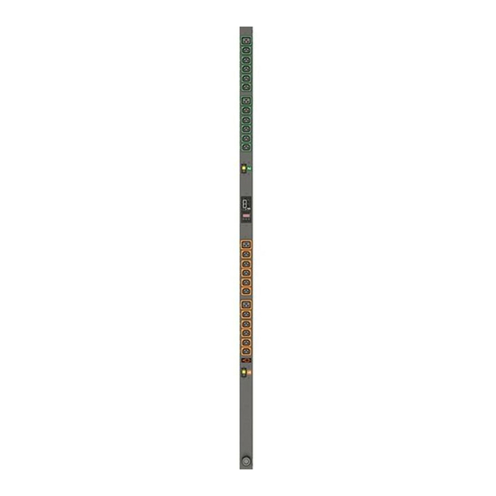
- Page 1 VERTIV INTELLIGENT RACK PDU VP8941, VP8641, VP5870V, VP5665V, VP8965, VP8932, VP8930, VP4551V, VP8959NA3, VP8959EU3 and VP8953 VertivCo.com/geist...
-
Page 2: Table Of Contents
VERTIV INTELLIGENT RACK PDU Page 2 CONTENTS Introduction............................. 6 1.1. Welcome ............................6 About this Manual........................... 9 2.1. Organization of the Manual ......................9 2.2. Audience Profile ..........................9 2.3. On-line Documentation ........................9 2.4. Reporting Document Errors ......................10 2.5. - Page 3 Cable Mount Brackets (CMB-1)................... 29 4.2.1.14. 19" Horizontal/Panel Mount Brackets (7938) .............. 30 4.2.2. Network Setup ........................31 Chapter 3 - Setup ..........................36 5.1. Interchangeable Monitoring Device (IMD-3E)................36 5.2. Vertiv Mobile App .......................... 44 5.3. Web Interface ..........................55...
- Page 4 VERTIV INTELLIGENT RACK PDU Page 4 5.4. Sensors ............................56 5.4.1. Overview ..........................56 5.4.1.1. Configuration and Operation ................... 58 5.4.2. Alarms & Warnings ......................62 5.4.2.1. Alarms & Warnings Configuration ................... 63 5.4.3. Logging ..........................67 5.5. System ............................69 5.5.1.
-
Page 5: Vertiv Intelligent Rack Pdu
VERTIV INTELLIGENT RACK PDU Page 5 6.1. Product-Specific Safety Notices....................98 6.1.1. General Safety........................98 6.1.2. Live Circuits Safety ......................98 6.1.3. Equipment Grounding......................99 6.1.4. Electrostatic Discharge ......................99 6.1.5. Explosive Environment ......................99 6.1.6. Servicing and Adjustments ....................99 6.1.7. -
Page 6: Introduction
1.1. W ELCOME Notice to Users Vertiv reserves the right to make changes to this document without notice to any user or reseller of this product. Vertiv also reserves the right to substitute or terminate distribution of this document, with no obligation to notify any person or party of such substitutions or terminations. - Page 7 Vertiv supports the intent of the law, which is the reduction of violence within the Democratic Republic of the Congo and will take several actions to both advance the goals of the Dodd-Frank Act and to provide exceptional support to our customers.
- Page 8 Nor shall Vertiv and its affiliates be liable for any damages, inclusive of loss of profits or data, arising from the use of or in connection with this document.
-
Page 9: About This Manual
VERTIV INTELLIGENT RACK PDU Page 9 2. ABO U T THIS M AN U AL This document provides an overview of Vertiv product(s), the major topics covered include: • Copyright, Trademarks, and Disclosure Restrictions. • Instructions for installing, powering and using the equipment. -
Page 10: Reporting Document Errors
VERTIV INTELLIGENT RACK PDU Page 10 2.4. REPORT ING DOCU MENT E RROR S Should you discover any error or identify a deficiency in this document, please take time to con- tact us at the following email address: Vertiv-Documents@vertivco.com Please be sure to provide us with the document name, part number, and page number(s). Also, please provide us with description of the error or the deficiency for the document. - Page 11 VERTIV INTELLIGENT RACK PDU Page 11 Figure 1 Overlay Symbology Guide...
-
Page 12: Safety
Page 12 2.5.3. SAFET Y This document contains varying levels of alerts pertaining to product and user safety. The alerts are visually presented with graphics and text per Vertiv equipment guidelines. The representations are: DANGER INDICATES AN IMMINENT HAZARDOUS SITUATION WHICH, IF NOT AVOIDED, W ILL RESULT IN DEATH OR SERIOUS INJURY. -
Page 13: Tables
VERTIV INTELLIGENT RACK PDU Page 13 2.5.4. FIGURES Figures presented in this document are identified and designated as follows: 'Figure:', Chapter # - Image # Example: Figure 1-1 Name and/or Title goes here 2.5.5. T ABLES Tables presented in this document are identified and designated as follows:... -
Page 14: Chapter 1 - Product Specifications
3.1. PRODU CT SPECIFI C AT IO NS 3.1.1. OVERVIEW The Vertiv Upgradeable second generation (GU2) product is a high tier rack level power distribution unit (PDU) with input and output monitoring, outlet level switching, remote network access via an embedded Vertiv API, and with external sensor support via built-in Enhanced Communications (EC) card. -
Page 15: Environmental
VERTIV INTELLIGENT RACK PDU Page 15 3.1.2. ENVIRON ME NT AL The operational environmental limits pertaining to Temperature, Humidity and Elevation are as defined below. 3.1.2.1. TEMPERATURE Table 1-2 Temperature Limits Minimum Maximum 60°C (140°F) UL Listed Models Operating 10°C (50°F) 50°C (122°F) CE Marked Models... -
Page 16: Receptacle Ratings
This product supports the following user interfaces: SNMP, JSON-based W eb GUI, JSON API, and Command-line interface using SSH. 3.1.5. REGULAT ORY CO MPLIAN C E Vertiv products are regulated for Safety, Emissions, and Environment Impact per the below agencies and policies. -
Page 17: Underwriters Laboratories (Ul)
VERTIV INTELLIGENT RACK PDU Page 17 3.1.5.1. UNDERW RITERS LABORATORIES (UL) UL Standards are used to assess products; test components, materials, systems and performance; and evaluate environmentally sustainable products, renewable energies, food and water products, recycling systems and other innovative technologies. -
Page 18: Rohs/Weee
VERTIV INTELLIGENT RACK PDU Page 18 3.1.5.4. ROHS/W EEE WEEE stands for Waste from Electrical and Electronic Equipment. W EEE Directive 2002/96/EC mandates the treatment, recovery and recycling of electric and electronic equipment (90% ends up in landfills). All applicable products in the EU market must pass WEEE compliance and carry the "Wheelie Bin" sticker. -
Page 19: Chapter 2 - Installation
VERTIV INTELLIGENT RACK PDU Page 19 4. CH AP TE R 2 - INS T ALL ATION 4.1. PRE-IN ST ALLAT ION • The ambient temperature of the installation location should be not greater than 60°C. NOTE Maximum environmental operating temperature is 60°C at full input and output nameplate rating, and with per receptacles max loading of 50% of outlet rating. -
Page 20: Installation
VERTIV INTELLIGENT RACK PDU Page 20 4.2. INST ALLAT ION 4.2.1. MO UNT ING Optional brackets sold separately. 1. Using appropriate hardware, mount unit to rack. (See below examples.) 2. Plug PDU into an appropriately-rated and protected branch-circuit receptacle. 3. Plug in the devices to be powered by the PDU. -
Page 21: Full Length Brackets
VERTIV INTELLIGENT RACK PDU Page 21 4.2.1.1. FULL LENGTH BRACKETS Figure 2-1 Full Length Bracket... -
Page 22: Mini "L" Brackets (Slb-4)
VERTIV INTELLIGENT RACK PDU Page 22 4.2.1.2. MINI "L" BRACKETS (SLB-4) Figure 2-2 Mini L Brackets... -
Page 23: Vertical Extension Brackets (Vcb-1)
VERTIV INTELLIGENT RACK PDU Page 23 4.2.1.3. VERTICAL EXTENSION BRACKETS (VCB-1) Figure 2-3 Vertical Extension Brackets... -
Page 24: Toolless Mounting Hardware (11621)
VERTIV INTELLIGENT RACK PDU Page 24 4.2.1.4. TOOLLESS MOUNTING HARDW ARE (11621) Figure 2-4 Toolless Mounting Hardware... -
Page 25: Toolless Full Length Brackets (Tlfl)
VERTIV INTELLIGENT RACK PDU Page 25 4.2.1.5. TOOLLESS FULL LENGTH BRACKETS (TLFL) Figure 2-5 Toolless Full Length Brackets 4.2.1.6. SINGLE SIDE MOUNT 2 UNIT BRACKETS (TSMX2) Figure 2-6 Single Side Mount 2 Units Brackets... -
Page 26: Offset/Side Mount Brackets (Ezb-1)
VERTIV INTELLIGENT RACK PDU Page 26 4.2.1.7. OFFSET/SIDE MOUNT BRACKETS (EZB-1) Figure 2-7 Offset/Side Mount Brackets... -
Page 27: 7" Extension Brackets (Xb-7)
VERTIV INTELLIGENT RACK PDU Page 27 4.2.1.8. 7" EXTENSION BRACKET S (XB-7) Figure 2-8 7" Extension Brackets 4.2.1.9. FLUSH MOUNT BRACKETS (FM) Figure 2-9 Flush Mount Brackets... -
Page 28: Adjustable Mount Brackets (Am)
VERTIV INTELLIGENT RACK PDU Page 28 4.2.1.10. ADJUSTABLE MOUNT BRACKETS (AM) Figure 2-10 Adjustable Mount Brackets 4.2.1.11. PANEL MOUNT BRACKETS (PM) Figure 2-11 Panel Mount Brackets... -
Page 29: 23" Conversion Mounting Brackets (23-Rm)
VERTIV INTELLIGENT RACK PDU Page 29 4.2.1.12. 23" CONVERSION MOUNT ING BRACKETS (23-RM) Figure 2-12 23" Conversion Mounting Brackets 4.2.1.13. 19" HORIZONTAL/PANEL MOUNT BRACKETS (7938) Figure 2-14 19" Horizontal/Panel Mount Brackets... -
Page 30: Network Setup
4.2.2. NETW ORK SET UP The Vertiv Upgradeable IMD has a default IP address for initial setup and access. To remove configured IP addresses and restore the unit to it's default IP address and reset all user-account information, if the user- assigned address or passwords are lost or forgotten, press and hold the network-reset button located below the Ethernet port number 2 for 5 seconds. - Page 31 VERTIV INTELLIGENT RACK PDU Page 31 · Windows 10: Click the Start button, then choose Network & Internet, then click Change adapter options. Locate the entry under LAN or High-Speed Internet or Local Area Connection which corresponds to the network card (NIC).
- Page 32 VERTIV INTELLIGENT RACK PDU Page 32 Find the entry titled "Internet Protocol Version 4 (TCP/IPv4)" in the list, then click the Properties button to open the Internet Protocol Properties window. If you see more than one TCP/IP entry, as in the ex- ample above, the computer may be configured for IPv6 support as well as IPv4;...
- Page 33 VERTIV INTELLIGENT RACK PDU Page 33 Note that the new settings will take effect when the Save button is clicked. The browser will no longer be able to reload the web page from the 192.168.123.123 address and will probably display a "page not found"...
- Page 34 VERTIV INTELLIGENT RACK PDU Page 34 Once the NIC settings are configured properly, you should be able to access the unit by typing http://192.168.123.123 into the address bar of your web browser. If you are setting up the unit for the first time, or if the unit has been reset back to factory defaults via the network-reset button, the unit will require you to create an Admin account and password before you can proceed.
-
Page 35: Chapter 3 - Setup
VERTIV INTELLIGENT RACK PDU Page 35 5. CH AP TE R 3 - SE TUP 5.1. INT ERCH ANGEA BLE MONI T ORING DEVI CE (I MD -3 E) The Interchangeable Monitoring Device (IMD) is the controller for the GU2 line of power products. The IMD can be replaced and upgraded to allow data-centers to future-proof their locations. - Page 36 VERTIV INTELLIGENT RACK PDU Page 36 5. Display Buttons: There are three buttons near the IMD display; a back button, a forward but- ton, and a center button. The functions of these buttons are as follows: Back Button Decrement to the previous channel.
- Page 37 6. Remote Sensor Port : RJ12 port for connecting a Vertiv plug-and-play remote digital sensors (sold separately). Each digital sensor has a unique serial number and is automatically discov- ered. GU2 PDUs support up to 16 sensors. The optional Vertiv A2D Converter can be added to support analog sensing.
- Page 38 PDU. Using a smart device, such as a smart phone or tablet with the Vertiv Mobile app installed, it is possible to capture data from the LED display when running in VLC mode, which can be enabled/disabled easily by using the display buttons on the device, or using the GUI on monitored units.
- Page 39 Certain custom models of Vertiv Upgradeable PDUs may not have VLC support within the Vertiv Mobile application. If your custom product is not supported by the Vertiv Mobile app it will be noted in the product specification sheet. Please contact your sales representative if you would like assistance with this.
- Page 40 PDU, put wrist strap on arm. 2. Insert Vertiv IMD Removal Tool as shown. Be sure to press tool in level and press in until tool is flush with face of IMD. Some older versions may require overlays to be removed prior to inserting tool.
- Page 41 VERTIV INTELLIGENT RACK PDU Page 41 Figure 3-3 IMD Removal Steps...
- Page 42 VERTIV INTELLIGENT RACK PDU Page 42 Installation 1. Connect the cable to the replacement IMD module. 2. Tuck the excess cable back into the PDU, and slide the IMD straight in. 3. Press with both thumbs until the IMD snaps into place.
-
Page 43: Vertiv Mobile App
Figure 3-5 Mobile App Home Screen • Scan: Turns on scan mode to allow the app to capture VLC data from Vertiv Upgradeable PDU. • Export: Pressing the export button will launch the smart device's email app and attach the Da-... - Page 44 VERTIV INTELLIGENT RACK PDU Page 44 Scanning a PDU Pressing the Scan button on the Home screen will load the Vertiv Mobile app scanning engine. Figure 3-6 Mobile App Scanning Screen To scan the PDU, position the smart device so that the characters on the LED display are between the lines on the screen.
- Page 45 Page 45 NOTE When a device is scanned for the first time, the Vertiv Mobile app will recog- nize the serial number as being new and ask if it should be added to the da- tabase as shown below. If added to the database, all future scanned data will be added to the device serial number record.
- Page 46 VERTIV INTELLIGENT RACK PDU Page 46 Proper capture methods: Figure 3-8 Mobile App Capture Screen • High Contrast between LED display and background • No glow around LED display characters • LED display characters between horizontal guidelines...
- Page 47 VERTIV INTELLIGENT RACK PDU Page 48 Improper capture methods: Figure 3-9 Mobile App Capture Misalignment • Blurry image • Over-exposed image • Glow around LED display characters • LED display characters not between horizontal guidelines...
- Page 48 Failure modes & Error messages: The Vertiv Mobile App will retry a scan 2 times if the scan cannot be completed. The scan can fail due to the smart device being unable to correctly capture all the VLC data correctly. If the app cannot properly...
- Page 49 VERTIV INTELLIGENT RACK PDU Page 50 Readings The Readings page displays scan results for each PDU scanned using VLC. Figure 3-11 Mobile App Readings Screen 1. Pressing the Settings button will enable the user to customized the data that is displayed in the scan results.
- Page 50 VERTIV INTELLIGENT RACK PDU Page 51 Figure 3-12 Mobile App Settings Screen • Collapse Rows: Allows user to collapse or expand the Readings page to help properly dis- play data on smart devices with smaller screens. • Unit Data to Display: Selects which data is shown on the Readings page. All data is stored within the database regardless of settings here.
- Page 51 NOTE An email app must be properly configured on the smart device to utilize the Export function. The Vertiv Mobile app does not directly support email func- tionality. Vertiv cannot troubleshoot email errors as this would be an issue with either the device, or email service being used.
- Page 52 VERTIV INTELLIGENT RACK PDU Page 53 The .csv data output organizes data first by serial number and then by date & time. You can further organ- ize the data by using the ‘Filter’ option in Excel. The data structure is split into two sections: 1.
- Page 53 VERTIV INTELLIGENT RACK PDU Page 54 Power Data 1 Volts 1 Amps 1 Watts 1 VA 1 kWh Input Phase for Phase Amperes Phase Real Power Phase Apparent Phase Kilowatt- Single Phase units. Power Hours Phase A or Phase AB if 3 Phase...
-
Page 54: Web Interface
.csv file. Data stored will vary based on product configuration. 5.3. W EB INT ERFACE The Vertiv Upgradeable Monitored units come with an embedded web interface. The unit is accessible via a standard, unencrypted HTTP connection, or via an encrypted HTTPS (TLS) connection. - Page 55 5.4. SEN SORS 5.4.1. OVERVIEW The Sensors Overview page displays the PDU's data. Vertiv Upgradeable PDUs measure power, voltage, current and energy. Readings on the Overview page are provided in real-time for all of the unit's measure- ments.
-
Page 56: Sensors
VERTIV INTELLIGENT RACK PDU Page 57 Sensors, System, and Help Tabs • Mouse over to show sub-menus: Table 3-2 Sensors, System, and Help Tabs Sensors System Help Overview Users Display Syslog Info Alarms & Warnings Network Time Admin Support Site... -
Page 57: Configuration And Operation
VERTIV INTELLIGENT RACK PDU Page 58 NOTE Groupings for Total, Phase, Circuit and Outlet Monitoring will vary depend- ing on the PDU's configuration and wiring. 5.4.1.1. CONFIGURATION AND OPERATION Configuration Icon Operation Icon NOTE Only users with control or admin level authorizations have access to these settings. - Page 58 VERTIV INTELLIGENT RACK PDU Page 59 Outlet Configuration: Click the desired Outlet Configuration icon. Figure 3-16 Outlet Configuration Page Configuration pop-up box will appear. Use the text box to change the outlet's Label. The outlet's state is described by three descriptors: •...
- Page 59 VERTIV INTELLIGENT RACK PDU Page 60 Click the Save button if any settings are changed. Device Operation: Click the Operation icon. Figure 3-17 Device Operation Page Select the operation you wish to perform: • On/Off turns on/off all outlets. •...
- Page 60 VERTIV INTELLIGENT RACK PDU Page 61 For operations involving the state of the outlets, setting Delay to True will use the current Delay config- uration for each outlet when performing the selected operation. Select Submit to issue the action. NOTE Power-on action delays reference the time since the unit was plugged in, not the time since it fully booted.
-
Page 61: Alarms & Warnings
VERTIV INTELLIGENT RACK PDU Page 62 Outlet Operation: Click the desired Outlet Operation icon. Figure 3-19 Outlet Operation Page The outlet's state is described by three descriptors: • State describes the outlet's current state (On/Off). • Pending State describes the state the outlet is currently transitioning to, if it is in the process of switching. -
Page 62: Alarms & Warnings Configuration
VERTIV INTELLIGENT RACK PDU Page 63 Events are displayed in different sections, based on the device or measurement the Event is associated with. Each Event can have one or more Actions to be taken when the Event occurs. Figure 3-20 Alarms & Warnings Page State: Shows the status of each Event. - Page 63 VERTIV INTELLIGENT RACK PDU Page 64 To add a new Alarm or Warning Event: Click the Add/Modify Alarms & W arnings button: Figure 3-21 Add/Modify Alarms & Warnings Page Set the desired conditions for this Event as follows: Select the Name of the phase or circuit you wish to set an Event on.
- Page 64 VERTIV INTELLIGENT RACK PDU Page 65 NOTE Only one valid time can be selected per alarm. Figure 3-22 Add Event Time The Invert Valid Time check box inverts the selected Valid Time setting. To determine where the alert notifications will be sent to when this particular Alarm or Warning...
- Page 65 Page 66 • Target is the e-mail address or SNMP manager to which notifications should be sent when the Event is tripped. Other options, such as "buzzer", may be available depending on your Vertiv PDU. • Delay determines how long this Event must remain tripped before this Action's first notification is sent.
-
Page 66: Logging
VERTIV INTELLIGENT RACK PDU Page 67 Click the Modify icon next to the Alarm or Warning Event you wish to change, then modify its settings as above. To delete an existing Alarm or Warning Event: Click the Delete icon next to the Alarm or Warning Event you wish to change, then click Delete to confirm. - Page 67 VERTIV INTELLIGENT RACK PDU Page 68 • Clicking on the CSV link will download the data log in .csv format for use in spreadsheet software such as Microsoft Excel. Log Interval • Change the frequency at which data is written to the log file. The logging interval can be 1-600 minutes with the default setting being 15 minutes.
-
Page 68: System
VERTIV INTELLIGENT RACK PDU Page 69 5.5. SYST E M 5.5.1. USE RS The Users page in the System menu allows you to manage or restrict access to the unit's features by cre- ating accounts for different users. Figure 3-27 User Account Page... - Page 69 VERTIV INTELLIGENT RACK PDU Page 70 Create the account information as follows: Username: the name of this account. Must be 1 to 32 characters in length. The first character must be 'a'-'z'. Subsequent characters must be 'a'-'z', '0'-'9', '-' or '_' Administrator: if set to True, this account has Administrator-level access to the unit, and can change any setting.
- Page 70 VERTIV INTELLIGENT RACK PDU Page 71 • Control: Control accounts (accounts with only Control set to True) have control over all settings per- taining to the device's sensors. They can add, modify, or delete Alarms & Warning Events and notifi- cation Actions, and can change the names or labels of the device and its sensors.
- Page 71 VERTIV INTELLIGENT RACK PDU Page 72 To Modify a user Account: Click the Modify User icon. Figure 3-29 Modify User Page 2. Modify the account information as follows: Language preference: Change the default language for this user. Options are English, French, Spanish, German, Portuguese, Japanese, Chinese and Korean.
- Page 72 VERTIV INTELLIGENT RACK PDU Page 73 Account Status: set the account to Enabled or Disabled. Disabling an account prevents it from being used to log in, but does not delete it from the account list. This option can only be modified by an Administrator level account.
-
Page 73: Network
VERTIV INTELLIGENT RACK PDU Page 74 5.5.2. NETW ORK The Unit’s network configuration is set on the network tab of the System Menu. Settings pertaining to the unit’s network connection are: Figure 3-31 Network Configuration Page... - Page 74 VERTIV INTELLIGENT RACK PDU Page 75 • Hostname: The Hostname may be used as a method for device identification on the network. • Interfaces: This section is used to configure the IP address of the PDU, enable/disable DHCP and to view Link State and Uptime.
- Page 75 VERTIV INTELLIGENT RACK PDU Page 76 NOTE Any changes you make to the Network Interface settings will take ef- fect once the Save button is clicked! If you have changed the IP ad- dress it will appear as if the unit is no longer responding because the browser will not be able to reload the web page.
- Page 76 VERTIV INTELLIGENT RACK PDU Page 77 Figure 3-34 Modify Existing IP Address To modify an existing IP Address: Click the Modify icon. Edit the IP Address and Prefix/Subnet Mask fields as needed. Click the Save button. Figure 3-35 Modify Port Settings To add a new Route: Click the Modify icon.
- Page 77 VERTIV INTELLIGENT RACK PDU Page 78 Figure 3-36 Add a New Route To add a new Route: Click the Add icon. Enter the appropriate information a. Destination IP address for desired route b. Enter Prefix for desired route c. Enter Gateway IP address d.
- Page 78 VERTIV INTELLIGENT RACK PDU Page 79 Click the Modify icon Edit the desired fields Click the Save button Figure 3-38 Add a New DNS Server Address To add a new DNS Server Address: Click the Add icon. Enter the IP of the desired DNS server. Up to two DNS servers can be added.
-
Page 79: Web Server
VERTIV INTELLIGENT RACK PDU Page 80 Use the RSTP section to Enable/Disable the RSTP Protocol, as well as make changes to RSTP settings. Enable: Enable or Disable RSTP protocol Mode: mode can be either "stp" or "rstp". RSTP mode supports falling back to STP when necessary. - Page 80 VERTIV INTELLIGENT RACK PDU Page 81 • HTTP/HTTPS Server Port: Allows you to change the TCP ports which the HTTP and HTTPS services listen to for incoming connections. The defaults are port 80 for HTTP and 443 for HTTPS. Figure 3-42 SSL Certificate Configuration Page •...
-
Page 81: Reports
VERTIV INTELLIGENT RACK PDU Page 82 5.5.4. REPORT S The Reports page allows the user to schedule the device to send recurring status reports. NOTE SMTP email must be set-up on the device via the Email page. Figure 3-43 Reports Page To Add or Modify a scheduled report: 1. -
Page 82: Ldap
VERTIV INTELLIGENT RACK PDU Page 83 5. Select the Target email address for the reports to be sent. 6. Click OK to save changes. To Delete a scheduled Report: 1. Click on the Delete icon next to the report to delete. - Page 83 VERTIV INTELLIGENT RACK PDU Page 84 • Bind Password: Password used to bind to the directory server. • Base DN: DN to use for the search base. The remaining fields come from the NIS schema, defined in RFC2307. They are used to authenticate us- ers in LDAP.
-
Page 84: Display
VERTIV INTELLIGENT RACK PDU Page 85 5.5.6. DISPL AY The unit's local display settings can be changed via the Display tab of the System menu. Figure 3-46 Display Mode The Display Mode section allows the user to configure what measurements are scrolling on the local dis- play. -
Page 85: Time
VERTIV INTELLIGENT RACK PDU Page 86 5.5.7. T IME The unit's time and date are set on this page. Figure 3-48 Time Configuration Page There are two mode available: Network Time Protocol (NTP) and Manual. NTP synchronizes the unit's time and date to the specified time zone using listed NTP Servers. NTP servers can be reconfigured. -
Page 86: Email
VERTIV INTELLIGENT RACK PDU Page 87 5.5.9. E MAIL The unit is capable of sending email notifications to up to ten email addresses when an Alarm or Warning Event occurs. Figure 3-50 Email Configuration Page Target email addresses can be configured as follows:... - Page 87 VERTIV INTELLIGENT RACK PDU Page 88 • Port: The TCP port which the SMTP Server uses to provide mail services. Typical values would be port 25 for an unencrypted connection, or 465 and 587 for a TLS/SSL-encrypted connection, but these may vary depending on the mail server's configuration.
-
Page 88: Snmp
VERTIV INTELLIGENT RACK PDU Page 89 5.5.10. SN MP Simple Network Management Protocol (SNMP) can be used to monitor the unit's measurements and sta- tus, if desired. SNMP v1, v2c and v3 are supported. In addition, alarm traps can be sent to up to two IP addresses. -
Page 89: Syslog
Syslog data can be captured remotely but must first be setup and enabled via the Syslog page. NOTE This function is primarily only useful for diagnostic purposes, and should normally be left Disabled unless advised to enable it by Vertiv technical sup- port for troubleshooting a specific issue. -
Page 90: Admin
VERTIV INTELLIGENT RACK PDU Page 91 Figure 3-57 Syslog Configuration Page Event log data can be downloaded by clicking on the CSV link at that top of the page. The event log will show system events such as user logins, configuration changes, service status, etc. The event log does not contain measurement data captured by the PDU as that data is located in the Data Log which can be found in the Sensors ->... -
Page 91: Locale
VERTIV INTELLIGENT RACK PDU Page 92 Figure 3-58 Admin Configuration Page 5.5.13. LO CALE The Locale page sets the default Language and Temperature Units for the device. These settings will be- come the default viewing options for the device, although individual users can change these options for their own accounts. - Page 92 Page 93 VERTIV INTELLIGENT RACK PDU The Configuration Backup and Restore section allows the user to backup the PDU configuration file for future use in the case that the device is reset to defaults for any reason. To download the current configuration click on the BIN link and save the file to an easily accessible loca- tion such as the local computer or a shared network folder.
-
Page 93: Help
Figure 3-64 Factory Access Page • Factory Access: Enabling Factory Access mode allows Vertiv support technicians access to more in-depth diagnostic information. It is recommended that this option be set to Disabled unless a Vertiv support member instructs you to enable it. -
Page 94: Support Site
Page 95 VERTIV INTELLIGENT RACK PDU Figure 3-65 Info Page 5.6.2. SUP PORT SIT E Technical support can be found at http://www.vertivco.com/support Phone Support • 1.800.432.3219... -
Page 95: Technical Support
5.7.3. USING MIC ROSOFT E X CHA NGE AS A N S MT P S ER VER If your facility uses a Microsoft Exchange email server, it can be used by the Vertiv Upgradeable PDU to send Alarm and Warning notification emails if desired. However, the Exchange server may need to be configured to allow SMTP connections from the unit first, as later version of Exchange often have SMTP services or basic authentication disabled by default. - Page 96 SMTP authentication and mail-relaying permis- sions correctly. If none of the above suggestions succeed in allowing your Vertiv Upgradeable PDU to send mail through your Exchange server, then you may need to contact Microsoft’s technical support for further assistance in configuring your Exchange server to allow SMTP emails to be sent from a 3rd-party, non-W indows device through your network.
-
Page 97: Chapter 4 - Final Checkout
Individuals using or maintaining Vertiv product(s) are expected to fol- low all the noted warnings and safety precautions necessary for safe operation of the equip- ment in your environment. Vertiv assumes no liability for failure to comply with these require- ments. - Page 98 Because of the danger of electrocution and/or severe health hazard, do not install substitute parts or preform any unauthorized modifications of this equipment. It is best to contact Vertiv for Warranty and Repair Service to ensure that safety features are maintained.
- Page 99 Page 100 VERTIV INTELLIGENT RACK PDU Thank You For Purchasing Your Vertiv Product VertivCo.com/geist...
Need help?
Do you have a question about the VP8641 and is the answer not in the manual?
Questions and answers