
Related Manuals for Vertiv NetSure 48BA1200-19


Summary of Contents for Vertiv NetSure 48BA1200-19
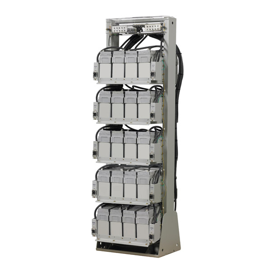
- Page 1 NetSure™ Battery Rack System (-48 VDC) Installation Manual (Section 6045), Revision E Specification Number: 588820100, 588820200 Model Number: 48BA1200-19, 48BA1200-23...
- Page 2 This document may contain confidential and/or proprietary information of Vertiv Group Corporation, and its receipt or possession does not convey any right to reproduce, disclose its contents, or to manufacture or sell anything that it may describe.
- Page 3 Installing Batteries into the Battery Shelves ................15 Installing Optional Front Battery Cover (23” Trays Only) ........... 19 Installing Optional Circuit Breaker Guard................... 20 Initially Starting the System ................20 Vertiv | NetSure Battery Rack System (-48 VDC) Installation Manual (Section 6045) | Rev. E...
- Page 4 SAFETY! Informs the reader of general safety information, reminders, precautions, or policies not related to a particular source of hazard or to fire safety. (ISO, ANSI, OSHA) Vertiv | NetSure Battery Rack System (-48 VDC) Installation Manual (Section 6045) | Rev. E...
- Page 5 Even a momentary short circuit can cause sparking, explosion, and injury. Vertiv | NetSure Battery Rack System (-48 VDC) Installation Manual (Section 6045) | Rev. E...
- Page 6 Only install in a ventilated environment. • Batteries are an energy source that can produce high amounts of electrical current. Vertiv | NetSure Battery Rack System (-48 VDC) Installation Manual (Section 6045) | Rev. E...
- Page 7 NOTE! When performing any step in procedures that requires removal of existing hardware, retain all hardware for use in subsequent steps, unless otherwise directed. Vertiv | NetSure Battery Rack System (-48 VDC) Installation Manual (Section 6045) | Rev. E...
- Page 8 This Page Intentionally Blank. Vertiv | NetSure Battery Rack System (-48 VDC) Installation Manual (Section 6045) | Rev. E...
- Page 9 The installer should be familiar with the installation requirements and techniques to be used in mounting the relay rack to the floor. Refer to Figure 1 or Figure 2 for floor mounting hole dimensions. Vertiv | NetSure Battery Rack System (-48 VDC) Installation Manual (Section 6045) | Rev. E...
- Page 10 Figure 1: Relay Rack Floor Mounting Hole Dimensions (588820100) Figure 2: Relay Rack Floor Mounting Hole Dimensions (588820200) Vertiv | NetSure Battery Rack System (-48 VDC) Installation Manual (Section 6045) | Rev. E...
- Page 11 REMOVE TAPE FROM HOLE LOCATIONS BEFORE INSTALLING LUG. Figure 3: Relay Rack Frame Grounding Connection Points Frame Ground Connection Point (1/4” clearance holes on 5/8” centers) Vertiv | NetSure Battery Rack System (-48 VDC) Installation Manual (Section 6045) | Rev. E...
- Page 12 Terminal Block (J3) accepts a wire size in the range of 26AWG to 14AWG (solid or stranded). Recommended Torque (J3): 0.5 to 0.6 Nm. Resistive Battery N.O. N.C. Com. Vertiv | NetSure Battery Rack System (-48 VDC) Installation Manual (Section 6045) | Rev. E...
- Page 13 300 in-lbs when using 3/8” bolts with a standard flat washer and lock washer. When connections are complete and verified, reinstall front and rear protective covers. Vertiv | NetSure Battery Rack System (-48 VDC) Installation Manual (Section 6045) | Rev. E...
- Page 14 Busbar Busbar Customer Battery Cable Customer Battery Cable Connections to Pwr. Sys. Connections to Pwr. Sys. Factory Battery Cable Connections Front Factory Battery Cable Connections Vertiv | NetSure Battery Rack System (-48 VDC) Installation Manual (Section 6045) | Rev. E...
- Page 15 ALERT! In the next step, observe correct polarity. Connect only cable labeled “+” to battery terminal labeled “+”. Likewise, connect only cable labeled “–” to battery terminal labeled “–”. Vertiv | NetSure Battery Rack System (-48 VDC) Installation Manual (Section 6045) | Rev. E...
- Page 16 If Battery Trays Are Equipped With Circuit Breakers: To connect the batteries to the Power System, turn ON the Battery Disconnect circuit breakers located on all battery trays. Vertiv | NetSure Battery Rack System (-48 VDC) Installation Manual (Section 6045) | Rev. E...
- Page 17 1/4-20 x 5/8" Hex Head Screw (4 Places) 1/4-20 Lock Washer (3 Places) 1/4-20 Flat Washer (3 Places) DETAIL A Alternate Orientation of Retention Bracket Vertiv | NetSure Battery Rack System (-48 VDC) Installation Manual (Section 6045) | Rev. E...
- Page 18 1/4-20 x 5/8" Hex Head Screw (4 Places) 1/4-20 Lock Washer (3 Places) 1/4-20 Flat Washer (3 Places) DETAIL A Alternate Orientation of Retention Bracket Vertiv | NetSure Battery Rack System (-48 VDC) Installation Manual (Section 6045) | Rev. E...
- Page 19 Assembled View Kit Battery Cover Kit Battery Cover Assembled to Existing Assembled to Existing Front Battery Bracket Front Battery Bracket Front View Rear View Vertiv | NetSure Battery Rack System (-48 VDC) Installation Manual (Section 6045) | Rev. E...
- Page 20 • If provided, ensure all battery circuit breakers are placed in the ON position. NOTE! Circuit breakers are provided with lockout/tagout capability. • Refer to any Initial Startup procedure in the documentation supplied with the respective power system. Vertiv | NetSure Battery Rack System (-48 VDC) Installation Manual (Section 6045) | Rev. E...
- Page 21 This Page Intentionally Blank. Vertiv | NetSure Battery Rack System (-48 VDC) Installation Manual (Section 6045) | Rev. E...
- Page 22 VertivCo.com | Vertiv Headquarters, 1050 Dearborn Drive, Columbus, OH, 43085, USA Section 6045 (RE 10/17)
Need help?
Do you have a question about the NetSure 48BA1200-19 and is the answer not in the manual?
Questions and answers