Table of Contents
Advertisement
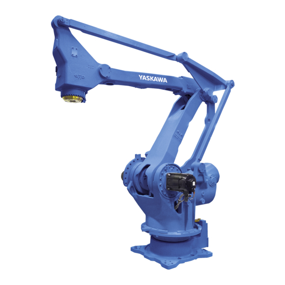
MOTOMAN-MPL100
INSTRUCTIONS
TYPE:
YR-MPL0100-A00 (STANDARD SPECIFICATION)
YR-MPL0100-A04 (WITH BUILT-IN TUBE FOR FIELDBUS CABLE)
Upon receipt of the product and prior to initial operation, read these instructions thoroughly, and retain
for future reference.
MOTOMAN INSTRUCTIONS
MOTOMAN-MPL100 INSTRUCTIONS
DX100 INSTRUCTIONS
DX100 OPERATOR'S MANUAL
DX100 MAINTENACE MANUAL
The DX100 operator's manual above corresponds to specific usage.
Be sure to use the appropriate manual.
Part Number:
157569-1CD
Revision:
4
MANUAL NO.
HW0485652
1 of 106
3
Advertisement
Table of Contents

Related Manuals for YASKAWA MOTOMAN-MPL100


Summary of Contents for YASKAWA MOTOMAN-MPL100
- Page 1 YR-MPL0100-A04 (WITH BUILT-IN TUBE FOR FIELDBUS CABLE) Upon receipt of the product and prior to initial operation, read these instructions thoroughly, and retain for future reference. MOTOMAN INSTRUCTIONS MOTOMAN-MPL100 INSTRUCTIONS DX100 INSTRUCTIONS DX100 OPERATOR’S MANUAL DX100 MAINTENACE MANUAL The DX100 operator’s manual above corresponds to specific usage.
- Page 2 Copyright © 2018, 2011 Yaskawa America, Inc. Terms of Use and Copyright Notice All rights reserved. This manual is freely available as a service to Yaskawa customers to assist in the operation of Motoman robots, related equipment and software This manual is copyrighted property of Yaskawa and may not be sold or redistributed in any way.
- Page 3 If such modification is made, the manual number will also be revised. • If your copy of the manual is damaged or lost, contact a YASKAWA representative to order a new copy. The representatives are listed on the back cover. Be sure to tell the representative the manual number listed on the front cover.
- Page 4 ALLOW UNTRAINED PERSONNEL TO OPERATE, PROGRAM, OR REPAIR THE EQUIPMENT! We recommend approved Yaskawa training courses for all personnel involved with the operation, programming, or repair of the equipment. This equipment has been tested and found to comply with the limits for a Class A digital device, pursuant to part 15 of the FCC rules.
- Page 5 Failure to observe this caution may result in electric shock or injury. • For disassembly or repair, contact your YASKAWA representative. • Do not remove the motor, and do not release the brake. Failure to observe these safety precautions may result in death or serious injury from unexpected turning of the manipulator's arm.
- Page 6 157569-1CD MPL100 Notes for Safe Operation WARNING • Before operating the manipulator, check that servo power is turned OFF pressing the emergency stop buttons. When the servo power is turned OFF, the SERVO ON LED on the programming pendant is turned OFF. Injury or damage to machinery may result if the emergency stop circuit cannot stop the manipulator during an emergency.
- Page 7 Read and understand the Explanation of Warning Labels in the DX100 Instructions before operating the manipulator: Definition of Terms Used In this Manual The MOTOMAN is the YASKAWA industrial robot product. The MOTOMAN usually consists of the manipulator, the controller, the programming pendant, and supply cables.
- Page 8 MOTOMAN- TYPE Do not enter PAYLOAD MASS robot DATE ORDER NO. work area. SERIAL NO. YASKAWA ELECTRIC CORPORATION 2-1 Kurosakishiroishi, Yahatanishi-ku, Kitakyushu 806-0004 Japan MADE IN JAPAN WARNING Label B: WARNING Moving parts may cause injury 8 of 106 viii...
- Page 9 157569-1CD MPL100 Safeguarding Tips Safeguarding Tips All operators, programmers, maintenance personnel, supervisors, and anyone working near the system must become familiar with the operation of this equipment. All personnel involved with the operation of the equipment must understand potential dangers of operation. General safeguarding tips are as follows: •...
- Page 10 Do not make any modifications to the controller unit. Making any changes without the written permission from Yaskawa will void the warranty. • Some operations require standard passwords and some require special passwords.
- Page 11 Turn the power OFF and disconnect and lockout/tagout all electrical circuits before making any modifications or connections. Perform only the maintenance described in this manual. Maintenance other than specified in this manual should be performed only by Yaskawa- trained, qualified personnel. Summary of Warning Information This manual is provided to help users establish safe conditions for operating the equipment.
- Page 12 If you need assistance with any aspect of your MPL100 system, please contact YASKAWA Customer Support at the following 24-hour telephone number: (937) 847-3200 For routine technical inquiries, you can also contact YASKAWA Customer Support at the following e-mail address: techsupport@motoman.com When using e-mail to contact YASKAWA Customer Support, please provide a detailed description of your issue, along with complete contact information.
-
Page 13: Table Of Contents
157569-1CD MPL100 Table of Contents Table of Contents 1 Product Confirmation ........................1-1 1.1 Contents Confirmation ....................... 1-1 1.2 Order Number Confirmation ....................1-2 2 Transport............................2-1 2.1 Transport Method ......................2-1 2.1.1 Using a Crane ...................... 2-2 2.2 Shipping Bolts and Brackets....................2-3 3 Installation............................ - Page 14 157569-1CD MPL100 Table of Contents 7 System Application.......................... 7-1 7.1 Peripheral Equipment Mounts.................... 7-1 7.2 Internal User I/O Wiring Harness and Air Line..............7-2 8 Electrical Equipment Specification ....................8-1 8.1 Position of Limit Switch ...................... 8-1 8.2 Internal Connections ......................8-2 9 Maintenance and Inspection ......................
-
Page 15: Product Confirmation
157569-1CD MPL100 Product Confirmation 1.1 Contents Confirmation Product Confirmation CAUTION • Confirm that the manipulator and the DX100 have the same order number. Special care must be taken when more than one manipulator is to be installed. If the numbers do not match, manipulators may not perform as expected and cause injury or damage. -
Page 16: Order Number Confirmation
157569-1CD MPL100 Product Confirmation 1.2 Order Number Confirmation Order Number Confirmation Check that the order number of the manipulator corresponds to the DX100. The order number is located on a label as shown below. Fig. 1-1: Location of Order Number Labels Label (Enlarged View) THE MANIPULATOR AND THE CONTROLLER Check that the manipulator... -
Page 17: Transport
157569-1CD MPL100 Transport 2.1 Transport Method Transport CAUTION • Sling applications and crane or forklift operations must be performed by authorized personnel only. Failure to observe this caution may result in injury or damage. • Avoid excessive vibration or shock during transport. The system consists of precision components. -
Page 18: Using A Crane
157569-1CD MPL100 Transport 2.1 Transport Method 2.1.1 Using a Crane As a rule, the manipulator should be lifted by a crane with four wire ropes when removing it from the package and moving it. Be sure that the manipulator is fixed with the shipping bolts and brackets before transport, and lift it in the posture as shown in Fig. -
Page 19: Shipping Bolts And Brackets
157569-1CD MPL100 Transport 2.2 Shipping Bolts and Brackets Shipping Bolts and Brackets The manipulator is provided with shipping bolts and brackets at positions A, B, and C. (See Fig. 2-1 “Transporting Position”.) • The shipping bolts and brackets are painted yellow. Position Screw Type Hexagon socket head cap screw M20... -
Page 20: Installation
157569-1CD MPL100 Installation Installation WARNING • Install the safeguarding. Failure to observe this warning may result in injury or damage. • Install the manipulator in a location where the tool or the workpiece held by its fully extended arm will not reach the wall, safeguarding, or controller. -
Page 21: Safeguarding Installation
157569-1CD MPL100 Installation 3.1 Safeguarding Installation Safeguarding Installation To insure safety, be sure to install safeguarding. It prevents unforeseen accidents with personnel and damage to equipment. Refer to the quoted clause for your information and guidance: Responsibility for Safeguarding (ISO10218) The user of a manipulator or robot system shall ensure that safeguards are provided and used in accordance with Sections 6, 7, and 8 of this standard. -
Page 22: Mounting Example
157569-1CD MPL100 Installation 3.2 Mounting Procedures for Manipulator Base 3.2.1 Mounting Example For the first process, anchor the baseplate firmly to the ground. The baseplate should be rugged and durable to prevent shifting of the manipulator or the mounting fixture. It is recommended to prepare a baseplate of 50 mm or more thickness, and anchor bolts of M24 or larger size. -
Page 23: Location
157569-1CD MPL100 Installation 3.3 Location Location When installing a manipulator, it is necessary to satisfy the following environmental conditions: • Ambient temperature: 0 to + 45C • Humidity: 20 to 80 %RH (non-condensing) • Free from dust, soot, or water •... -
Page 24: Wiring
157569-1CD MPL100 Wiring 4.1 Grounding Wiring WARNING Ground resistance must be 100 or less. • Failure to observe this warning may result in fire or electric shock. • Before wiring, make sure to turn the primary power supply off, and put up a warning sign. -
Page 25: Cable Connection
157569-1CD MPL100 Wiring 4.2 Cable Connection Fig. 4-1: Grounding Method Bolt M8 (for grounding) Delivered with the manipulator Enlarged View A 5.5 mm or more Cable Connection Three manipulator cables are delivered with the manipulator: an encoder cable (1BC) and two power cables (2BC and 3BC). (Refer to Fig. 4-2 “Manipulator Cables”.) Connect these cables to the manipulator base connectors and to the DX100. - Page 26 157569-1CD MPL100 Wiring 4.2 Cable Connection Fig. 4-2: Manipulator Cables DX100 side Manipulator side Encoder Cable Manipulator side DX100 side Power Cable DX100 side Manipulator side Power Cable 26 of 106 HW0485652...
- Page 27 157569-1CD MPL100 Wiring 4.2 Cable Connection Fig. 4-3(a): Manipulator Cable Connectors (Manipulator Side, YR-MPL0100-A00) positions Connector Details (Manipulator Side) Fig. 4-3(b): Manipulator Cable Connectors (Manipulator Side, YR-MPL0100-A04) positions Connector Details (Manipulator Side) 27 of 106 HW0485652...
- Page 28 157569-1CD MPL100 Wiring 4.2 Cable Connection Fig. 4-3(c): Manipulator Cable Connection (DX100 Side) 28 of 106 HW0485652...
-
Page 29: Basic Specifications
157569-1CD MPL100 Basic Specifications 5.1 Basic Specifications Basic Specifications Basic Specifications Table 5-1: Basic Specifications Item Type YR-MPL0100-A00, A04 Structure Vertically Articulated Degree of Freedom Payload 100 kg Repeatability ±0.5 mm Range of Motion S-Axis (turning) ±180 L-Axis (lower arm) +90, -45... -
Page 30: Part Names And Working Axes
157569-1CD MPL100 Basic Specifications 5.2 Part Names and Working Axes Part Names and Working Axes Fig. 5-1: Part Names and Working Axes Upper arm (U-arm) Wrist Wrist flange Lower arm L-arm Rotary head S-head Base Manipulator Base Dimensions Fig. 5-2: Manipulator Base Dimensions 220±0.1 220±0.1 +0.021... -
Page 31: Dimensions And T-Point Maximum Envelope
157569-1CD MPL100 Basic Specifications 5.4 Dimensions and T-Point Maximum Envelope Dimensions and T-Point Maximum Envelope Fig. 5-3: Dimensions and P-Point Maximum Envelope (YR-MPL0100-A00, A04) 1300 1600 2776 2162 1400 R1124 2204 P-point T -Point 1241 -point maximum envelope Units: mm 1037 3159 31 of 106... -
Page 32: Alterable Operating Range
Alterable Operating Range The operating range of the S-axis can be altered in accordance with the operating conditions as shown in Table 5-2 "S-Axis Operating Range". If alteration is necessary, contact your YASKAWA representative in advance. Table 5-2: S-Axis Operating Range... -
Page 33: Components For Altering Operating Range
157569-1CD MPL100 Basic Specifications 5.5 Alterable Operating Range 5.5.1 Components for Altering Operating Range When modifying the operating range of the S-axis, prepare the components shown in Fig. 5-4 “Components of S-Axis Stopper” referring to the following list. (1) Pin (drawing No. HW0407007-1, 1 pin) (2) Stopper (drawing No. -
Page 34: Notes On The Mechanical Stopper Installation
157569-1CD MPL100 Basic Specifications 5.5 Alterable Operating Range 5.5.2 Notes on the Mechanical Stopper Installation • Apply the Locktite 242 to the thread part of the pin HW0407007-1, and install the pin bottom up into the S-axis mechanical stopper HW0307574-1 as shown in Fig. 5-4 “Components of S-Axis Stopper”. Mount the stopper to the S-head with three hexagon head screws M20 (length: 70 mm) and tighten the screws to the tightening torque of ... -
Page 35: Adjustment Of The Soft Limit Of The S-Axis Pulse
157569-1CD MPL100 Basic Specifications 5.5 Alterable Operating Range 5.5.3 Adjustment of the Soft Limit of the S-Axis Pulse To limit the operating range of the S-axis, refer to "DX100 Concurrent I/O (manual No. RE-CKI-A453)" and change the following parameters with the programming pendant. - Page 36 157569-1CD MPL100 Basic Specifications 5.5 Alterable Operating Range Table 5-3: Settable Angle for S-Axis Stopper 36 of 106 HW0485652...
- Page 37 157569-1CD MPL100 Basic Specifications 5.5 Alterable Operating Range Fig. 5-6(a): Properly-Mounted Models for S-Axis Stopper The stopper is reversible. Either side of the stopper can be used. Hexagon head screw M20 (3 screws) (length: 70 mm) with three washers M20 Installation at + 180°...
- Page 38 157569-1CD MPL100 Basic Specifications 5.5 Alterable Operating Range Fig. 5-6(b): Properly-Mounted Models for S-Axis Stopper The stopper is irreversible. Only this side of the stopper can be used at this angle. Hexagon head screw M20 (3 screws) (length: 70 mm) with three washers M20 Installation at + 150°...
- Page 39 157569-1CD MPL100 Basic Specifications 5.5 Alterable Operating Range Fig. 5-6(c): Properly-Mounted Models for S-Axis Stopper The stopper is irreversible. Only this side of the stopper can be used at this angle. Hexagon head screw M20 (3 screws) (length: 70 mm) with three washers M20 Installation at + 120°...
- Page 40 157569-1CD MPL100 Basic Specifications 5.5 Alterable Operating Range Fig. 5-6(d): Properly-Mounted Models for S-Axis Stopper The stopper is reversible. Either side of the stopper can be used. Hexagon head screw M20 (3 screws) (length: 70 mm) with three washers M20 Installation at + 90°...
- Page 41 157569-1CD MPL100 Basic Specifications 5.5 Alterable Operating Range Fig. 5-6(e): Properly-Mounted Models for S-Axis Stopper The stopper is irreversible. Only this side of the stopper can be used at this angle. Hexagon head screw M20 (3 screws) (length: 70 mm) with three washers M20 Installation at + 60°...
- Page 42 157569-1CD MPL100 Basic Specifications 5.5 Alterable Operating Range Fig. 5-6(f): Properly-Mounted Models for S-Axis Stopper Hexagon head screw M20 (3 screws) (length: 70 mm) The stopper is irreversible. with three washers M20 Only this side of the stopper can be used at this angle. Installation at + 30°...
- Page 43 157569-1CD MPL100 Basic Specifications 5.5 Alterable Operating Range Fig. 5-6(g): Properly-Mounted Models for S-Axis Stopper Hexagon head screw M20 (3 screws) (length: 70 mm) with three washers M20 The stopper is reversible. Either side of the stopper can be used. Installation at + 0°...
- Page 44 157569-1CD MPL100 Basic Specifications 5.5 Alterable Operating Range Fig. 5-6(h): Properly-Mounted Models for S-Axis Stopper The stopper is reversible. Either side of the stopper can be used. Hexagon head screw M20 (3 screws) (length: 70 mm) 180 ° with three washers M20 Installation at - 180°...
- Page 45 157569-1CD MPL100 Basic Specifications 5.5 Alterable Operating Range Fig. 5-6(i): Properly-Mounted Models for S-Axis Stopper Hexagon head screw M20 (3 screws) (length: 70 mm) with three washers M20 The stopper is irreversible. Only this side of the stopper can be used at this angle. Installation at - 150°...
- Page 46 157569-1CD MPL100 Basic Specifications 5.5 Alterable Operating Range Fig. 5-6(j): Properly-Mounted Models for S-Axis Stopper Hexagon head screw M20 (3 screws) (length: 70 mm) with three washers M20 The stopper is irreversible. Only this side of the stopper can be used at this angle. Installation at - 120°...
- Page 47 157569-1CD MPL100 Basic Specifications 5.5 Alterable Operating Range Fig. 5-6(k): Properly-Mounted Models for S-Axis Stopper Hexagon head screw M20 (3 screws) (length: 70 mm) The stopper is reversible. with three washers M20 Either side of the stopper Installation at - 90° can be used.
- Page 48 157569-1CD MPL100 Basic Specifications 5.5 Alterable Operating Range Fig. 5-6(l): Properly-Mounted Models for S-Axis Stopper Hexagon head screw M20 (3 screws) (length: 70 mm) with three washers M20 The stopper is irreversible. Only this side of the stopper can be used at this angle. Installation at - 60°...
- Page 49 157569-1CD MPL100 Basic Specifications 5.5 Alterable Operating Range Fig. 5-6(m): Properly-Mounted Models for S-Axis Stopper Hexagon head screw M20 (3 screws) (length: 70 mm) with three washers M20 The stopper is irreversible. Only this side of the stopper can be used at this angle. Installation at - 30°...
-
Page 50: Allowable Load For Wrist Axis And Wrist Flange
157569-1CD MPL100 Allowable Load for Wrist Axis and Wrist Flange 6.1 Allowable Wrist Load Allowable Load for Wrist Axis and Wrist Flange Allowable Wrist Load The allowable wrist load including the weight of the mount/gripper is 100 kg maximum. 1. - Page 51 157569-1CD MPL100 Allowable Load for Wrist Axis and Wrist Flange 6.1 Allowable Wrist Load Fig. 6-1: Moment Arm Rating for MPL100 Center of T-axis flange rotation LT (mm) 1000 900 800 700 600 500 400 300 200 100 100 200 300 400 500 600 700 800 900 1000 W=100 kg W=80 kg...
-
Page 52: Wrist Flange
157569-1CD MPL100 Allowable Load for Wrist Axis and Wrist Flange 6.2 Wrist Flange Wrist Flange The wrist flange dimensions are shown in Fig. 6-2 “Wrist Flange”. It is recommended that the attachment be mounted inside the fitting in order to identify the alignment marks. -
Page 53: Levelness Of The Wrist Flange
157569-1CD MPL100 Allowable Load for Wrist Axis and Wrist Flange 6.3 Levelness of the Wrist Flange Levelness of the Wrist Flange The wrist flange is kept level to the mounting surface of the MOTOMAN- MPL100 in the full range of motion. However, minor tilting may occur due to the posture and load conditions. -
Page 54: System Application
157569-1CD MPL100 System Application 7.1 Peripheral Equipment Mounts System Application Peripheral Equipment Mounts The peripheral equipment mounts and tapped holes are provided on the wrist unit as shown in Fig. 7-1 “Installing Peripheral Equipment” for easier installation of the users’ system applications. The following conditions shall be observed to attach or install peripheral equipment. -
Page 55: Internal User I/O Wiring Harness And Air Line
157569-1CD MPL100 System Application 7.2 Internal User I/O Wiring Harness and Air Line Internal User I/O Wiring Harness and Air Line Internal user I/O wiring harness (0.5 mm x 23 wires), and air lines (6 lines for A00 and 5 lines for A04) are incorporated in the manipulator for the drive of peripheral devices mounted on the upper arm as shown in Fig. - Page 56 157569-1CD MPL100 System Application 7.2 Internal User I/O Wiring Harness and Air Line Fig. 7-2(a): Connectors for Internal User I/O Wiring Harness and Air Line (YR-MPL0100-A00) Connector for the internal user I/O wiring harness (wrist side): JL05-2A24-28SC (with a cap) Prepare connector: JL05-6A24-28P Exhaust port: A, B, C, D, E, F PT3/8 with a pipe plug (6 places)
- Page 57 157569-1CD MPL100 System Application 7.2 Internal User I/O Wiring Harness and Air Line Fig. 7-2(b): Connectors for Internal User I/O Wiring Harness and Air Line (YR-MPL0100-A04) Cable B (See "Note 1" below.) Tube for field bus cable (inside dia.: 12) Details of Part Y (inside the junction box of the wrist) Part Y...
- Page 58 157569-1CD MPL100 System Application 7.2 Internal User I/O Wiring Harness and Air Line Note 2: As shown in Fig. 7-2(c) “Field Bus Cable Connection”, the tube for a field bus cable (inside dia.: 12 mm) is connected by a union in the Z part of the S- head.
- Page 59 157569-1CD MPL100 System Application 7.2 Internal User I/O Wiring Harness and Air Line Fig. 7-2(d): Details of the Connector Pin Numbers 11 12 18 19 20 Pins used Internal user I/O wiring harness: 23 wires, size 0.5 mm The same numbered pins (1 to 23) of the two connectors are connected with a single lead wire of 0.5 mm 59 of 106 HW0485652...
- Page 60 System Application 7.2 Internal User I/O Wiring Harness and Air Line The wrist part of MOTOMAN-MPL100 has a hollow structure for the internal user I/O wiring harness, air line, etc. To run the internal user I/O wiring harness, air line, etc. through the hollow part, follow the conditions below.
-
Page 61: Electrical Equipment Specification
157569-1CD MPL100 Electrical Equipment Specification 8.1 Position of Limit Switch Electrical Equipment Specification Position of Limit Switch The limit switches are optional. For the S-, L-, and U-axes with limit switches specifications, the limit switches are located on the S-axis, L-axis, and U-axis respectively. -
Page 62: Internal Connections
157569-1CD MPL100 Electrical Equipment Specification 8.2 Internal Connections Internal Connections Highly reliable connectors are equipped on each connection part of the manipulator to enable easy removal and installation for maintenance and inspection. For the number and location of connectors, see Fig. 8-2(a) “Locations and Numbers of Connectors (YR-MPL0100-A00)”... - Page 63 157569-1CD MPL100 Electrical Equipment Specification 8.2 Internal Connections Fig. 8-2(b): Locations and Numbers of Connectors (YR-MPL0100-A04) Connector for internal user Connector for internal user I/O wiring harness I/O wiring harness Enlarged View A Enlarged View B Table 8-1: List of Connector Types Name Type of Connector Connector for the internal user I/O...
- Page 64 157569-1CD MPL100 8 Electrical Equipment Specification 8.2 Internal Connections Fig. 8-3(a): Internal Connection Diagram Notes 1. For the limit switch specification, the connection of the section 0BAT11 0BAT1 parts are changed as follows: P BAT BAT11 BAT1 0BAT12 0BAT2 P BAT BAT12 BAT2 0BAT3...
- Page 65 157569-1CD MPL100 8 Electrical Equipment Specification 8.2 Internal Connections Fig. 8-3(b): Internal Connection Diagram X21(8X5) 2BC(8X5) CN1-1 CN1-1 CN1-2 CN1-2 CN1-3 CN1-3 CN1-4 CN1-4 CN1-5 CN1-5 CN1-6 CN1-6 No.9CN CN1-7 CN1-7 9CN-A CN1-8 CN1-8 CN2-1 CN2-1 CN2-2 CN2-2 CN2-3 CN2-3 S-axis CN2-4 CN2-4...
-
Page 66: Maintenance And Inspection
Failure to observe this caution may result in electric shock or injury. • For disassembly or repair, contact your YASKAWA representative. • DO NOT remove the motor, and DO NOT release the brake. Failure to observe this caution may result in injury from unexpected turning of the manipulator’s arm. - Page 67 157569-1CD MPL100 Maintenance and Inspection 9.1 Inspection Schedule • The inspection interval depends on the total servo operation time. • The following inspection schedule is based on the case that each axis is used under normal conditions. For axes which are used very frequently (in handling applications, etc.), it is recommended that inspections be conducted at intervals of 1/2 of the schedule indicated in Table 9-1 NOTE...
- Page 68 Table 9-1: Inspection Items (Sheet 1 of 2) Items Schedule Method Operation Inspection Charge • • • • Alignment mark Visual Check alignment mark accordance and damage at the home position. • • • • External lead Visual Check for damage and deterioration of leads. •...
- Page 69 Table 9-1: Inspection Items (Sheet 2 of 2) Items Schedule Method Operation Inspection Charge • • • Battery pack in manipulator Screwdriver, Replace the battery pack when the battery alarm Wrench occurs or the manipulator drove for 36000H. See section 9.2.1 “Battery Pack Replacement”. •...
- Page 70 1 Inspection item numbers correspond to the numbers in Fig. 9-1 “Inspection Items”. 2 The occurrence of a grease leakage indicates the possibility that grease has seeped into the motor. This can cause a motor breakdown. Contact your YASKAWA representative.
- Page 71 Fig. 9-1: Inspection Items View A U-axis T-axis L-axis S-axis 71 of 106...
-
Page 72: Notes On Maintenance Procedures
157569-1CD MPL100 Maintenance and Inspection 9.2 Notes on Maintenance Procedures Table 9-2: Inspection Parts and Grease Used Grease Used Inspected Parts 13, 14, 15 Molywhite RE No.00 Speed reducers for S-, L-, U- and T-axes 9, 16 Alvania EP Grease 2 L-axis balancer, bearings The numbers in the above table correspond to the numbers in Table 9-1 "Inspection Items"... - Page 73 157569-1CD MPL100 Maintenance and Inspection 9.2 Notes on Maintenance Procedures Fig. 9-2(c): Battery Location (Top View) Battery pack Board Fig. 9-3: Battery Connection Battery pack before replacement See the step 5. Connector Board See the step 4. New battery pack (HW0470360-A) 1.
-
Page 74: Notes On Grease Replenishment/Exchange Procedures
157569-1CD MPL100 Maintenance and Inspection 9.3 Notes on Grease Replenishment/Exchange Procedures 6. Mount the new battery pack to the holder. 7. Reinstall the plate. Do not allow the plate to pinch the cables when reinstalling NOTE the plate. Notes on Grease Replenishment/Exchange Procedures Make sure to follow the instructions listed below at grease replenishment/ exchange. -
Page 75: Grease Replenishment/Exchange For S-Axis Speed Reducer And Gear
157569-1CD MPL100 Maintenance and Inspection 9.3 Notes on Grease Replenishment/Exchange Procedures 9.3.1 Grease Replenishment/Exchange for S-Axis Speed Reducer and Gear Fig. 9-4: S-Axis Speed Reducer and Gear Diagram Grease exhaust port Hexagon socket head plug Grease inlet Hexagon socket head plug S-axis speed reducer 9.3.1.1 Grease Replenishment (Refer to Fig. -
Page 76: Grease Exchange
157569-1CD MPL100 Maintenance and Inspection 9.3 Notes on Grease Replenishment/Exchange Procedures 6. Remove the grease zerk from the grease inlet, and reinstall the plug. Before installing the plug, apply Three Bond 1206C on the thread part of the plug. Then tighten the plug with a tightening torque of 4.9 N•m (0.5 kgf•m). -
Page 77: Grease Replenishment/Exchange For L-Axis Speed Reducer
157569-1CD MPL100 Maintenance and Inspection 9.3 Notes on Grease Replenishment/Exchange Procedures 9.3.2 Grease Replenishment/Exchange for L-Axis Speed Reducer Fig. 9-5(a): L-Axis Speed Reducer Diagram L-axis speed reducer Grease exhaust port Hexagon socket head plug Grease inlet Hexagon socket head plug Section A-A’... - Page 78 157569-1CD MPL100 Maintenance and Inspection 9.3 Notes on Grease Replenishment/Exchange Procedures 9.3.2.1 Grease Replenishment (Refer to Fig. 9-5(a) “L-Axis Speed Reducer Diagram” and Fig. 9-5(b) “L- Axis Grease Replenishment”.) 1. Remove the hexagon socket head plugs from the grease inlet and grease exhaust port.
- Page 79 157569-1CD MPL100 Maintenance and Inspection 9.3 Notes on Grease Replenishment/Exchange Procedures CAUTION • If the L-arm is tilted at 80 degrees or more, the link-C interferes with the plug for air exhaust. Do not tilt the L-arm over 80 degrees when verifying the manipulator operation.
- Page 80 157569-1CD MPL100 Maintenance and Inspection 9.3 Notes on Grease Replenishment/Exchange Procedures 4. The grease exchange is completed when new grease appears in the grease exhaust port. (The new grease can be distinguished from the old grease by color.) 5. Move the L-axis for a few minutes to discharge excess grease. 6.
-
Page 81: Grease Replenishment
157569-1CD MPL100 Maintenance and Inspection 9.3 Notes on Grease Replenishment/Exchange Procedures 9.3.3 Grease Replenishment/Exchange for U-Axis Speed Reducer Fig. 9-6: U-Axis Speed Reducer Diagram Grease exhaust port Hexagon socket head plug Grease inlet U-axis speed Hexagon socket head plug reducer 9.3.3.1 Grease Replenishment (Refer to Fig. - Page 82 157569-1CD MPL100 Maintenance and Inspection 9.3 Notes on Grease Replenishment/Exchange Procedures 5. Wipe the discharged grease with a cloth, and reinstall the plug. Before installing the plug, apply Three Bond 1206C on the thread part of the plug. Then tighten the plug with a tightening torque of 24.5 N•m (2.5 kgf•m).
-
Page 83: Grease Replenishment
157569-1CD MPL100 Maintenance and Inspection 9.3 Notes on Grease Replenishment/Exchange Procedures 9.3.4 Grease Replenishment/Exchange for T-Axis Speed Reducer Fig. 9-7: T-Axis Speed Reducer Diagram Grease exhaust port Hexagon socket head plug T-axis speed reducer Grease inlet Hexagon socket head plug 9.3.4.1 Grease Replenishment (Refer to Fig. -
Page 84: Grease Exchange
157569-1CD MPL100 Maintenance and Inspection 9.3 Notes on Grease Replenishment/Exchange Procedures If the plug is installed while grease is being exhausted, grease will leak inside the motor and may cause a damage. NOTE Make sure to install the plug when the grease exhaust is completed. -
Page 85: Grease Replenishment For U-Axis Cross Roller Bearing
157569-1CD MPL100 Maintenance and Inspection 9.3 Notes on Grease Replenishment/Exchange Procedures 9.3.5 Grease Replenishment for U-axis Cross Roller Bearing Fig. 9-8: U-Axis Cross Roller Bearing Diagram Exhaust port U-axis cross roller bearing Hexagon socket head plug Grease inlet Hexagon socket head plug 1. -
Page 86: Grease Replenishment For Links
157569-1CD MPL100 Maintenance and Inspection 9.3 Notes on Grease Replenishment/Exchange Procedures 9.3.6 Grease Replenishment for Links Fig. 9-9: Grease Replenishment for Links 86 of 106 9-21 HW0485652... - Page 87 157569-1CD MPL100 Maintenance and Inspection 9.3 Notes on Grease Replenishment/Exchange Procedures 1. Remove the hexagon socket head plug PT1/8 from the exhaust port of each link. (Refer to Fig. 9-9 “Grease Replenishment for Links”) 2. Remove the hexagon socket head plug PT1/8 from the grease inlet of each link and install the grease zerk A-PT1/8.
-
Page 88: Notes For Maintenance
157569-1CD MPL100 Maintenance and Inspection 9.3 Notes on Grease Replenishment/Exchange Procedures 9.3.7 Notes for Maintenance When performing maintenance such as replacement of a wire harness in the manipulator, the encoder connector may be necessary to be removed. In this case, be sure to connect the battery pack to the battery backup connector before removing the encoder connector. - Page 89 157569-1CD MPL100 Maintenance and Inspection 9.3 Notes on Grease Replenishment/Exchange Procedures Fig. 9-10: Battery Pack Connection Motor Motor power connector Connector for motor encoder 0BT* BAT* Battery pack: HW9470932-A Battery backup connector a: Crimped contact-pin (pin) b: Crimped contact-pin (socket) 89 of 106 9-24 HW0485652...
-
Page 90: Recommended Spare Parts
10 Recommended Spare Parts It is recommended to keep the parts and components in the following table in stock as spare parts for the MOTOMAN-MPL100. Product performance cannot be guaranteed when using spare parts from any company other than YASKAWA. The spare parts are ranked as follows: •... - Page 91 Recommended Spare Parts Table 10-1: Spare Parts for the YR-MPL0100-A00, -A04 (Sheet 2 of 2) Rank Parts Name Type Manufacturer Remarks Unit U-axis Cross HW9482144-A YASKAWA Roller Bearing Electric Corporation AC Servomotor for SGMRV-44ANA-YR1* YASKAWA S-, L-, and U-axes HW0389698-A Electric...
-
Page 92: Parts List
157569-1CD MPL100 Parts List 11.1 S-Axis Unit 11 Parts List 11.1 S-Axis Unit Fig. 11-1: S-Axis Unit 1072 1005 1071 1069 1006 1070 1082 1080 1081 1075 1076 1068 1037 1039 1038 1026 1011 1034 1014 1001 1077 1022 1013 1029 1015 1078... - Page 93 157569-1CD MPL100 Parts List 11.1 S-Axis Unit Table 11-1: S-Axis Unit (Sheet 1 of 2) DWG No. Name 1001 SGMRV-44ANA-YR1* Motor 1002 HW0281280-A Speed reducer 1003 M8X100 Socket screw 1004 2H-8 Spring washer 1005 M16X70 Socket screw 1006 2H-16 Spring washer 1011 HW0101143-1 S-head...
- Page 94 157569-1CD MPL100 Parts List 11.1 S-Axis Unit Table 11-1: S-Axis Unit (Sheet 2 of 2) DWG No. Name 1051 HW9405304-* Shim 1052 O-ring 1053 HW9405048-1 Housing 1054 2H-8 Spring washer 1055 M8X25 Socket screw 1056 2H-5 Spring washer 1057 M5X16 Socket screw 1058 IRTW-72...
-
Page 95: L-Axis Unit
157569-1CD MPL100 Parts List 11.2 L-Axis Unit 11.2 L-Axis Unit Fig. 11-2(a): L-Axis Unit 2077 2076 2003 2055 2041 2085 2035 2058 2056 2043 2031 2076 2078 2059 2057 2077 2008 2045 2002 2041 2054 2040 2039 2067 2072 2070 2075 2074 2073... - Page 96 157569-1CD MPL100 Parts List 11.2 L-Axis Unit Fig. 11-2(b): L-Axis Unit 2034 2031 2035 2035 2095 2006 2094 2039 2008 2040 2045 2045 2045 2028 2021 2016 2001 2092 2080 2086 2093 2015 2087 2017 2022 2014 2045 2018 2045 2002 2019...
- Page 97 157569-1CD MPL100 Parts List 11.2 L-Axis Unit Table 11-2: L-Axis Unit (Sheet 1 of 2) DWG No. Name 2001 SGMRV-44ANA-YR1* Motor 2002 HW0101144-1 L-arm 2003 HW0101146-1 Link A 2004 HW9482144-A Cross roller bearing 2005 HW9301736-1 B-cover 2006 HW9200827-1 M-base 2007 HW0200685-1 M-base 2008...
- Page 98 157569-1CD MPL100 Parts List 11.2 L-Axis Unit Table 11-2: L-Axis Unit (Sheet 2 of 2) DWG No. Name 2046 HW0307641-1 Shaft 2047 HW0406922-1 B-cover 2048 HW0406923-1 Pup washer 2051 HW9405055-1 Shaft 2052 HW9405699-1 B-cover 2053 HW9302054-1 Shaft 2054 HW0308094-1 Link-C 2055 HW0400016-1 Shaft...
-
Page 99: U-Axis Unit
157569-1CD MPL100 Parts List 11.3 U-Axis Unit 11.3 U-Axis Unit Fig. 11-3: U-Axis Unit 3022 3005 3034 3030 3030 3032 3023 3023 2054 3032 3009 3027 3023 3009 3033 3032 3022 3034 3034 3030 3022 3009 3024 3032 3030 3005 3027 3023 3015... - Page 100 157569-1CD MPL100 Parts List 11.3 U-Axis Unit Table 11-3: U-Axis Unit DWG No. Name 3001 HW9403571-2 Shaft 3002 HW9301405-1 B-cover 3003 HW9403656-* Shim 3004 AG4059E0 Oil seal 3005 PT1/8 Plug 3006 HR32016XJ Bearing 3007 M6X6 Socket screw 3008 2H-6 Spring washer 3009 M6X20 GT-SA Bolt...
-
Page 101: Wrist Unit
157569-1CD MPL100 Parts List 11.4 Wrist Unit 11.4 Wrist Unit Fig. 11-4: Wrist Unit 4045 4045 4022 4001 4029 4024 4017 4018 4037 4044 4012 4032 4011 4046 4010 4038 4019 4015 4020 4014 4004 4033 4024 3039 4013 3037 4008 4038 4009... - Page 102 157569-1CD MPL100 Parts List 11.4 Wrist Unit Table 11-4: Wrist Unit (Sheet 1 of 2) DWG No. Name 4001 SGMRV-13ANA-YR1* Motor 4002 HW0381150-C Speed reducer 4003 HW0102580-1 Wrist base 4004 HW0406923-1 Pup washer 4005 O-ring 4006 HW0406922-1 B-cover 4007 HW0484003-A Bearing 4008 HW0307641-1...
- Page 103 157569-1CD MPL100 Parts List 11.4 Wrist Unit Table 11-4: Wrist Unit (Sheet 2 of 2) DWG No. Name 4045 M8X25 GT-SA Bolt 4046 M6X20 GT-SA Bolt 4047 M10X20 Socket screw 4048 2H-10 Spring washer 4049 M4X10 GT-SA Bolt 4050 M8X80 Socket screw 4051 2H-8...
-
Page 104: Balancer Unit
157569-1CD MPL100 Parts List 11.5 Balancer Unit 11.5 Balancer Unit Fig. 11-5: Balancer Unit 5018 5019 5011 5004 5020 5007 5005 5002 5017 5006 5016 5015 5012 5003 5008 5003 5012 5014 5010 5013 5009 104 of 106 11-13 HW0485652... - Page 105 157569-1CD MPL100 Parts List 11.5 Balancer Unit Table 11-5: Balancer Unit DWG No. Name 5002 HW0481740-A Coil spring 5003 SOB607440 OILES bearing 5004 HW0100477-1 Case 5005 HW0306033-1 Flange 5006 HW0200420-1 Flange 5007 HW0401112-1 Flange 5008 HW0303581-1 5009 HW9405057-1 Clevis 5010 FD3187A0 Dust seal 5011...
- Page 106 INSTRUCTIONS HEAD OFFICE 2-1 Kurosakishiroishi, Yahatanishi-ku, Kitakyushu 806-0004, Japan Phone +81-93-645-7703 Fax +81-93-645-7802 YASKAWA America Inc. (Motoman Robotics Division) 100 Automation Way, Miamisburg, OH 45342, U.S.A. Phone +1-937-847-6200 Fax +1-937-847-6277 YASKAWA Europe GmbH Robotics Divsion ) Yaskawastrasse 1, 85391 Allershausen, Germany...
Need help?
Do you have a question about the MOTOMAN-MPL100 and is the answer not in the manual?
Questions and answers