Table of Contents
Advertisement
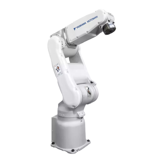
MOTOMAN-MH5S(II)/MH5F
MAINTENANCE MANUAL
TYPE:
YR-MH0005F-A00 (STANDARD SPECIFICATION)
YR-MH0005S-A00 (STANDARD SPECIFICATION)
YR-MH0005S-J00 (STANDARD SPECIFICATION)
Procedures described in this maintenance manual should be carried out by the person who took
the maintenance-relevant trainings offered by YASKAWA.
Upon receipt of the product and prior to initial operation, read these instructions thoroughly, and
retain for future reference.
MOTOMAN INSTRUCTIONS
MOTOMAN-MH5S/MH5F INSTRUCTIONS
MOTOMAN-MH5S II INSTRUCTIONS
DX100 INSTRUCTIONS
DX100 OPERATOR'S MANUAL
DX100 MAINTENANCE MANUAL
DX200 INSTRUCTIONS
DX200 OPERATOR'S MANUAL (for each purpose)
DX200 MAINTENANCE MANUAL
FS100 INSTRUCTIONS
FS100 OPERATOR'S MANUAL
FS100 MAINTENANCE MANUAL
The controller operator's manual above correspond to a specific usage. Be sure to use the appropriate manual.
Part Number:
176183-1CD
Revision:
1
MANUAL NO.
HW1483638
2
1 of 99
Advertisement
Table of Contents


Need help?
Do you have a question about the MOTOMAN-MH5S and is the answer not in the manual?
Questions and answers