Table of Contents
Advertisement
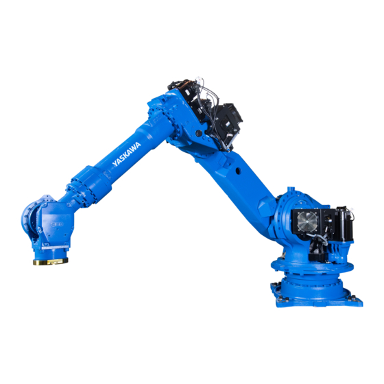
MOTOMAN-PH130F
MAINTENANCE MANUAL
TYPE:
YR-1-06VXF130-A00
(MOTOMAN-PH130F STANDARD SPECIFICATION)
Procedures described in this maintenance manual should be carried out by the person who took
the maintenance-relevant trainings offered by YASKAWA.
Upon receipt of the product and prior to initial operation, read these instructions thoroughly, and
retain for future reference.
MOTOMAN INSTRUCTIONS
MOTOMAN-PH130F INSTRUCTIONS
YRC1000 INSTRUCTIONS
YRC1000 OPERATOR'S MANUAL (GENERAL) (SUBJECT SPECIFIC)
YRC1000 MAINTENANCE MANUAL
YRC1000 ALARM CODES (MAJOR ALARMS) (MINOR ALARMS)
The YRC1000 operator's manual above corresponds to specific usage. Be sure to use the appropriate manual.
The YRC1000 operator's manual above consists of "GENERAL" and "SUBJECT SPECIFIC".
The YRC1000 alarm codes above consists of "MAJOR ALARMS" and "MINOR ALARMS".
187273-1CD
0
MANUAL NO.
HW1485471
1/134
Advertisement
Table of Contents

Related Manuals for YASKAWA MOTOMAN-PH130F


Summary of Contents for YASKAWA MOTOMAN-PH130F
- Page 1 (MOTOMAN-PH130F STANDARD SPECIFICATION) Procedures described in this maintenance manual should be carried out by the person who took the maintenance-relevant trainings offered by YASKAWA. Upon receipt of the product and prior to initial operation, read these instructions thoroughly, and retain for future reference.
-
Page 2: Table Of Contents
HW1485471 Contents 1 Introduction ............................. 1-1 2 Notes for Maintenance ........................2-1 2.1 Details of Internal Connections ..................2-1 2.2 Multi-Port Connector ......................2-3 3 Home Position Return ........................3-1 3.1 Home Position Posture of Manipulator ................3-1 3.2 Types of Methods for Home Position Return ..............3-2 3.2.1 Using a Teaching Point for Setting the Home Position......... - Page 3 HW1485471 Contents 5.2.2 Applying Sealing Bond to Sealing Surface ............5-10 5.2.3 Assembling After Applying Sealing Bond ............5-11 6 Disassembly and Reassembly of the Motors.................. 6-1 6.1 Disassembly and Reassembly of the S-Axis Motor ............6-2 6.2 Disassembly and Reassembly of the L-Axis Motor ............6-6 6.3 Disassembly and Reassembly of U-Axis Motor...............
- Page 4 HW1485471 Contents 12.3 U-, R-, B-, T-Axis Unit ....................12-7 12.4 U-arm unit ........................12-10 12.5 Wrist unit ........................12-12 12.6 Balancer Unit ....................... 12-15 HW1485471 4/134...
-
Page 5: Introduction
If such modification is made, the manual number will also be revised. • If your copy of the manual is damaged or lost, contact a YASKAWA representative to order a new copy. The representatives are listed on the back cover. Be sure to tell the representative the manual number listed on the front cover. - Page 6 HW1485471 Introduction Notes for Safe Operation Read this manual carefully before installation, operation, maintenance, or inspection of your manipulator. In this manual, the Notes for Safe Operation are classified as “DANGER”, “WARNING”, “CAUTION”, or “NOTICE”. Indicates an imminently hazardous DANGER situation which, if not avoided, will result in death or serious injury.
- Page 7 WARNING • Maintenance and inspection must be performed by specified personnel. Failure to observe this caution may result in electric shock or injury. • For disassembly or repair, contact your YASKAWA representative. HW1485471 7/134...
- Page 8 HW1485471 Introduction DANGER • Before operating the manipulator, make sure the servo power is turned OFF by performing the following operations. When the servo power is turned OFF, the SERVO ON LED on the programming pendant is turned OFF. – Press the emergency stop buttons on the front door of the YRC1000, on the programming pendant, on the external control device, etc.
- Page 9 Failure to observe this instruction may result in the loss of home position data. Definition of Terms Used Often in This Manual The MOTOMAN is the YASKAWA industrial robot product. The MOTOMAN usually consists of the manipulator, the YRC1000, the programming pendant, and supply cables.
- Page 10 Also, an identification label with important information is placed on the body of the manipulator. Prior to operating the manipulator, confirm the contents. Note: Taking the maintenance-relevant trainings offered by YASKAWA is indispensable for replacing the L-axis of the balancer-equipped manipulator.
- Page 11 HW1485471 Introduction Fall down hazard label Description Make sure to secure the manipulator base by using the bolts of the specified sizes and by tightening the bolts with the specified tightening torques. If the power is turned ON and the manipulator is operated without securing the manipulator properly, the manipulator may fall down, which may result in personal injury and/or equipment damage.
- Page 12 HW1485471 Introduction Crush hazard label Description Keep clear of moving parts when performing a teaching operation within the manipulator's operating range. Failure to observe this instruction may result in personal injury. Balancer disassembly prohibited label Description Do not disassemble the balancer. When disassembling the balancer, the internal energy is released and the L-arm rotates.
-
Page 13: Notes For Maintenance
HW1485471 Notes for Maintenance Details of Internal Connections Notes for Maintenance Details of Internal Connections For the encoder and the power supply of the motor of each axis, lead wires are connected to each part of the manipulator. When replacing a motor or lead wire, prepare the necessary parts and perform maintenance operations by referring to fig. - Page 14 HW1485471 Notes for Maintenance Details of Internal Connections Table 2-1: Details of Internal Connections Item Qty. Note S-axis motor Encoder cable: Not provided with the motor Power cable: Not provided with the motor L-axis motor Encoder cable: Not provided with the motor Power cable: Not provided with the motor...
-
Page 15: Multi-Port Connector
HW1485471 Notes for Maintenance Multi-Port Connector Multi-Port Connector Three multi-port connectors (refer to fig. 2-2 “Multi-Port Connector” ) for the encoders of the motors are provided on the manipulator. (For the locations, refer to fig. 2-4 “Locations of Battery Pack and Multi-Port Connector”... - Page 16 HW1485471 Notes for Maintenance Multi-Port Connector Fig. 2-4: Locations of Battery Pack and Multi-Port Connector Cable tie Protective tube Battery for U-, R-axes Battery pack for B-, T-axes Multi-port connector Cable tie When the Cover is Removed Fixing bolt for the cover Cross head APS bolt M4 (length: 8 mm) (3 bolts) Cover...
-
Page 17: Home Position Return
HW1485471 Home Position Return Home Position Posture of Manipulator Home Position Return Reset the home position of the manipulator if the home NOTE position is cleared or deviated. The YRC1000 stores the position data of the job program (hereinafter called JOB) as the pulse number from the home position of each axis. -
Page 18: Types Of Methods For Home Position Return
HW1485471 Home Position Return Types of Methods for Home Position Return Types of Methods for Home Position Return This section explains the types of methods for home position return in detail. 3.2.1 Using a Teaching Point for Setting the Home Position As a preparation, create the standard position for home position adjustment under normal operating conditions. -
Page 19: Methods For Home Position Return
HW1485471 Home Position Return Methods for Home Position Return Methods for Home Position Return 3.3.1 Using a Teaching Point for Setting the Home Position 3.3.1.1 Preparation Before the replacement of a motor or a speed reducer, the standard position (hereinafter called the check-point) must be created for home position adjustment. -
Page 20: Home Position Adjustment
HW1485471 Home Position Return Methods for Home Position Return 3.3.1.3 Home Position Adjustment After the replacement, move the axis whose motor or speed reducer was replaced to the position of the home position mark, and register the home position tentatively. For details, refer to chapter 8.1 “Home Position Calibration”... -
Page 21: Using Keys
HW1485471 Home Position Return Methods for Home Position Return 3.3.2 Using Keys The parts in table 3-2 “Parts List” are required. Prepare them beforehand. Table 3-2: Parts List Drawing No. Name Qty. Note HW9405595-1 For S-, L-, U-, R-, B- and T-axes HW0300669-1 Plate Plate for R-axis... - Page 22 HW1485471 Home Position Return Methods for Home Position Return 2. L-Axis Positioning As shown in fig. 3-3 “L-Axis Positioning” , insert the pin (HW9405595- 1) from the pin hole ( +0.012 ) on the S-head and perform positioning 6 dia. by using the programming pendant so that the pin fits into the hole of the L-arm.
- Page 23 HW1485471 Home Position Return Methods for Home Position Return 4. R-Axis Positioning As shown in fig. 3-5 “R-Axis Positioning” , insert two pins (HW1408161-6- 20) into the U-arm, and then mount the plate (HW0300669-1). Insert the pin (HW9405595-1) from the hole ( +0.012 ) of the plate 6 dia.
-
Page 24: Using Encoder Backup Error Recovery Function
Pin hole (6 dia. Wrist 3.3.3 Using Encoder Backup Error Recovery Function For details on the encoder backup error recovery function, refer to “YRC1000 INSTRUCTIONS (RE-CTO-A221)”. 3.3.4 Robot Calibration (MOTOCALV EG) Contact your YASKAWA representative for the procedure of robot calibration. HW1485471 24/134... -
Page 25: Axis Fixing Jig
HW1485471 L-Axis Fixing Jig Fixing Jig L-Axis Fixing Jig DANGER • The maintenance operation should be carried out by a specified person. • Execute disassembly and reassembly of the L-axis motor after mounting the L-axis fixing jig on the balancer. After mounting the L- axis fixing jig, be sure to confirm that the L-axis is firmly fixed by releasing the L-axis motor brake. -
Page 26: Recommended Installation Posture Of The Specified Fixing Jig
HW1485471 L-Axis Fixing Jig Fixing Jig 4.1.1 Recommended Installation Posture of the Specified Fixing Jig When using this fixing jig, operating the manipulator in the posture shown in fig. 4-1 “Recommended Installation Posture of the Specified Fixing Jig” is recommended. L-axis: -60°... -
Page 27: Range Of L-Arm Postures To Avoid
HW1485471 L-Axis Fixing Jig Fixing Jig 4.1.2 Range of L-Arm Postures to Avoid Avoid operating the manipulator in the posture shown in fig. 4-2 “Range of L-Arm Postures to Avoid” as much as possible. The flange tip may move several hundred millimeters. If there are objects in the surrounding area that will interfere with this operation, operate the turning axis or other axes and move the manipulator to a posture without interference. -
Page 28: Installation And Removal Of The L-Axis Fixing Jig
HW1485471 L-Axis Fixing Jig Installation and Removal of the L-axis Fixing Jig Installation and Removal of the L-axis Fixing Jig Refer to table 4-1 “Parts Check List of L-Axis Fixing Jig” , fig. 4-3 “Details of Specified Jig Installation” , and fig. 4-4 “Details of Specified Jig Removal”... - Page 29 HW1485471 L-Axis Fixing Jig Installation and Removal of the L-axis Fixing Jig Table 4-1: Parts Check List of L-Axis Fixing Jig No. Name Qty. Note Rubber cap Hexagon socket head cap screw M8 Tightening torque: 24.5 N•m (length: 16 mm) each Conical spring washer 2L-8 Stud HW0400632-1...
- Page 30 HW1485471 L-Axis Fixing Jig Installation and Removal of the L-axis Fixing Jig Fig. 4-3: Details of Specified Jig Installation Before installing the jig M36XP2 M55XP2 Case After installing the jig HW1485471 30/134...
- Page 31 HW1485471 L-Axis Fixing Jig Installation and Removal of the L-axis Fixing Jig Fig. 4-4: Details of Specified Jig Removal M36XP2 M55XP2 Case Before removing the jig Case When using the jig for removal After removing the jig HW1485471 31/134...
-
Page 32: Mechanism
HW1485471 L-Axis Fixing Jig Mechanism Mechanism • Refer to fig. 4-5 “The L-arm Rotation Direction” . The L-arm rotational direction of when L-axis holding power is released depends on the extent of the torque Tb generated by the balancer, and the load torque TL generated around the L-axis. -
Page 33: Notes On Grease Replenishment/Exchange Procedures
HW1485471 Notes on Grease Replenishment/Exchange Procedures Grease Exchange Procedures for Each Axis Speed Reducer Notes on Grease Replenishment/Exchange Procedures Grease Exchange Procedures for Each Axis Speed Reducer 5.1.1 Notes on Grease Exchange Procedures Make sure to follow the instructions listed below at grease replenishment/ exchange. - Page 34 HW1485471 Notes on Grease Replenishment/Exchange Procedures Grease Exchange Procedures for Each Axis Speed Reducer WARNING When operating the manipulator, do not enter into the working area of the manipulator. Injury may result if anyone enter into the working area during the operation. HW1485471 34/134...
-
Page 35: Grease Exchange Procedure
HW1485471 Notes on Grease Replenishment/Exchange Procedures Grease Exchange Procedures for Each Axis Speed Reducer 5.1.2 Grease Exchange Procedure Fig. 5-1: Grease Inlets and Exhaust Ports for Each Axis Grease exhaust port of S-axis (Hexagon socket head plug PT3/8) S-axis speed areducer Grease inlet of S-axis (Hexagon socket head plug PT1/4) Grease exhaust port of L-axis... - Page 36 HW1485471 Notes on Grease Replenishment/Exchange Procedures Grease Exchange Procedures for Each Axis Speed Reducer 1. Before injecting grease, the posture of the manipulator must be set as indicated in table 5-1 “Recommended Posture for Grease Injection” . If it is difficult to make the recommended posture because of the external cabling or etc., adjust the posture as much as possible to set the position of the grease inlet face the lower part and the position of exhaust port face the upper part.
- Page 37 HW1485471 Notes on Grease Replenishment/Exchange Procedures Grease Exchange Procedures for Each Axis Speed Reducer 5. Injection stop: – <When replacing the speed reducer> Stop injecting grease when grease can be seen from the exhaust port. – <When exchanging grease> The old grease is discharged from the grease exhaust port. At this time, stop injection when the mixture of the old grease and the new grease in an equal ratio is seen.
- Page 38 HW1485471 Notes on Grease Replenishment/Exchange Procedures Grease Exchange Procedures for Each Axis Speed Reducer Method 2: Suctioning grease out (1) Keep the inlet open and insert the tube into the exhaust port. (2) Discharge grease by suctioning grease out of the exhaust port. (Suction pressure: 0.025 MPa or less) (3) If grease is not discharged by suctioning, operate the manipulator again about 5 times in the teach mode as shown in table 5-3...
- Page 39 HW1485471 Notes on Grease Replenishment/Exchange Procedures Grease Exchange Procedures for Each Axis Speed Reducer Table 5-6: Plug Type and Tightening Torque for Each Axis Axis to exchange grease Plug for the grease inlet Plug for the grease exhaust port Plug type Tightening torque Plug type Tightening torque...
-
Page 40: Grease Replenishment For Balancer Link Part
HW1485471 Notes on Grease Replenishment/Exchange Procedures Grease Exchange Procedures for Each Axis Speed Reducer 5.1.3 Grease Replenishment for Balancer Link Part Fig. 5-3: Balancer Link Part Link air exhaust port Link air exhaust port (Hexagon socket head plug PT1/8) (Hexagon socket head plug PT1/8) Link grease inlet Link... -
Page 41: Removing, Applying, Assembling Of Sealing Bond
HW1485471 Notes on Grease Replenishment/Exchange Procedures Removing, Applying, Assembling of Sealing Bond Removing, Applying, Assembling of Sealing Bond 5.2.1 Removing Sealing Bond from Sealing Surface and Cleaning 1. Remove the sealing bond of the sealing surface of the manipulator on which the speed reducer or the motor was mounted by using a spatula etc. -
Page 42: Applying Sealing Bond To Sealing Surface
HW1485471 Notes on Grease Replenishment/Exchange Procedures Removing, Applying, Assembling of Sealing Bond 5.2.2 Applying Sealing Bond to Sealing Surface 1. Check that the degreasing and cleaning agent of the sealing surface is dried. (Refer to fig. 5-5 “Checking the Dryness” .) If not dried, wipe the agent with a new cloth. -
Page 43: Assembling After Applying Sealing Bond
HW1485471 Notes on Grease Replenishment/Exchange Procedures Removing, Applying, Assembling of Sealing Bond 5.2.3 Assembling After Applying Sealing Bond 1. After applying sealing bond, pay attention to the following and immediately perform assembling. • Remove any dust, dirt, foreign objects, and oil on the sealing surface. -
Page 44: Disassembly And Reassembly Of The Motors
HW1485471 Disassembly and Reassembly of the Motors Disassembly and Reassembly of the Motors WARNING Because the motor is removed, the manipulator cannot keep its posture during the replacement of the motor or speed reducer. When replacing the motor or speed reducer, hold the manipulator arm by using a hanging tool (e.g., chain block). -
Page 45: Disassembly And Reassembly Of The S-Axis Motor
HW1485471 Disassembly and Reassembly of the Motors Disassembly and Reassembly of the S-Axis Motor Disassembly and Reassembly of the S-Axis Motor • Refer to fig. 6-2(a) “Disassembly and Reassembly of the S-Axis Motor” . Disassembly 1. Turn OFF the power supply of the YRC1000. 2. - Page 46 HW1485471 Disassembly and Reassembly of the Motors Disassembly and Reassembly of the S-Axis Motor 7. Insert the power connector to the S-axis motor by aligning the key position as shown in fig. 6-2(e) “Motor Power Cable” , and turn the coupling nut of the connector on the cable side until it makes a clicking sound.
- Page 47 HW1485471 Disassembly and Reassembly of the Motors Disassembly and Reassembly of the S-Axis Motor Fig. 6-2(a): Disassembly and Reassembly of the S-Axis Motor Tapped hole for eyebolt (2 places) (diagonal) Tapped hole for motor (4 places) Apply sealing bond here. Gear case Fig.
- Page 48 HW1485471 Disassembly and Reassembly of the Motors Disassembly and Reassembly of the S-Axis Motor Fig. 6-2(d): Surface to Apply Sealing Bond on the S-Axis Flywheel Apply sealing bond evenly to Apply sealing bond evenly to whole surface. whole surface. Apply sealing Apply sealing bond here.
-
Page 49: Disassembly And Reassembly Of The L-Axis Motor
HW1485471 Disassembly and Reassembly of the Motors Disassembly and Reassembly of the L-Axis Motor Disassembly and Reassembly of the L-Axis Motor DANGER • Execute disassembly and reassembly of the L-axis motor after mounting the L-axis fixing jig on the balancer. Also, be sure to confirm that the L-axis is firmly fixed by releasing the L-axis motor brake. - Page 50 HW1485471 Disassembly and Reassembly of the Motors Disassembly and Reassembly of the L-Axis Motor Reassembly For removing/applying of sealing bond and assembling after NOTE applying sealing bond, refer to chapter 5.2 “Removing, Applying, Assembling of Sealing Bond” . 1. Mount the key on the L-axis motor .
- Page 51 HW1485471 Disassembly and Reassembly of the Motors Disassembly and Reassembly of the L-Axis Motor Table 6-2: L-Axis Motor Parts Checklist Item Qty. Note L-axis motor SGM7G-44APK-YR1* Hexagon socket head cap screw Tightening torque 84.0 N•m M12 (length: 35 mm) *trivalent chro- each mate* Conical spring washer 2H-12 *triva-...
- Page 52 HW1485471 Disassembly and Reassembly of the Motors Disassembly and Reassembly of the L-Axis Motor Fig. 6-3(a): Disassembly and Reassembly of the L-Axis Motor S-head Apply sealing bond here. Fig. 6-3(b): Surface to Apply Sealing Bond on the L-axis Motor Apply sealing bond evenly Surface to apply to whole surface.
- Page 53 HW1485471 Disassembly and Reassembly of the Motors Disassembly and Reassembly of the L-Axis Motor Fig. 6-3(c): Motor Power Cable Main key Coupling nut Alignment mark HW1485471 53/134 6-10...
-
Page 54: Disassembly And Reassembly Of U-Axis Motor
HW1485471 Disassembly and Reassembly of the Motors Disassembly and Reassembly of U-Axis Motor Disassembly and Reassembly of U-Axis Motor • Refer to fig. 6-4(a) “Disassembly and Reassembly of the U-Axis Motor” . Disassembly 1. Support the U-arm with the chain block, etc. 2. - Page 55 HW1485471 Disassembly and Reassembly of the Motors Disassembly and Reassembly of U-Axis Motor Reassembly For removing/applying of sealing bond and assembling after NOTE applying sealing bond, refer to chapter 5.2 “Removing, Applying, Assembling of Sealing Bond” . 1. Mount the key on the U-axis motor .
- Page 56 HW1485471 Disassembly and Reassembly of the Motors Disassembly and Reassembly of U-Axis Motor Table 6-3: U-Axis Motor Parts Checklist Item Qty. Note U-axis motor SGM7G-37APK-YR1* Hexagon socket head cap screw Tightening torque 84.0 N•m M12 (length: 40 mm) *trivalent each chromate* Conical spring washer 2H-12 *trivalent chromate*...
- Page 57 HW1485471 Disassembly and Reassembly of the Motors Disassembly and Reassembly of U-Axis Motor Fig. 6-4(a): Disassembly and Reassembly of the U-Axis Motor Casing Apply sealing bond here. L-arm HW1485471 57/134 6-14...
- Page 58 HW1485471 Disassembly and Reassembly of the Motors Disassembly and Reassembly of U-Axis Motor Fig. 6-4(b): Surface to Apply Sealing Bond on the U-axis Motor Apply sealing bond Surface to apply evenly to whole surface. sealing bond 2 Apply sealing bond evenly to whole surface.
-
Page 59: Disassembly And Reassembly Of The R-, B-, T-Axis Motors
HW1485471 Disassembly and Reassembly of the Motors Disassembly and Reassembly of the R-, B-, T-Axis Motors Disassembly and Reassembly of the R-, B-, T-Axis Motors • Make the U-arm point downwards as much as possible at disassembly or reassembly of the R-, B-, T-axis motor. - Page 60 HW1485471 Disassembly and Reassembly of the Motors Disassembly and Reassembly of the R-, B-, T-Axis Motors Reassembly For removing/applying of sealing bond and assembling after NOTE applying sealing bond, refer to chapter 5.2 “Removing, Applying, Assembling of Sealing Bond” . 1.
- Page 61 HW1485471 Disassembly and Reassembly of the Motors Disassembly and Reassembly of the R-, B-, T-Axis Motors Table 6-4: R-, B-, and T-Axis Motor Parts Checklist Item Qty. Note R-, B-, and T-axis motor 1 each SGM7G-13APK-YR1* ×3 Hexagon socket head cap screw M8 4 each Tightening torque 24.5 N•m (length: 25 mm) *trivalent chromate*...
- Page 62 HW1485471 Disassembly and Reassembly of the Motors Disassembly and Reassembly of the R-, B-, T-Axis Motors Fig. 6-5(a): Disassembly and Reassembly of the R-, B-, T-Axis Motors Apply sealing bond here. B-axis R-axis T-axis R-axis T-axis B-axis View A HW1485471 62/134 6-19...
- Page 63 HW1485471 Disassembly and Reassembly of the Motors Disassembly and Reassembly of the R-, B-, T-Axis Motors Fig. 6-5(b): Surface to Apply Sealing Bond on the R-, B-, and T-Axis Motors Apply sealing bond evenly Surface to apply to whole surface. sealing bond 2 Surface to apply sealing bond 1...
-
Page 64: Disassembly And Reassembly Of The Speed Reducers
HW1485471 Disassembly and Reassembly of the Speed Reducers Disassembly and Reassembly of S-Axis Speed Reducer Disassembly and Reassembly of the Speed Reducers Disassembly and Reassembly of S-Axis Speed Reducer • Refer to fig. 7-1(a) “Disassembly and Reassembly of the S-Axis Speed Reducer”... - Page 65 HW1485471 Disassembly and Reassembly of the Speed Reducers Disassembly and Reassembly of S-Axis Speed Reducer Reassembly For removing/applying of sealing bond and assembling after NOTE applying sealing bond, refer to chapter 5.2 “Removing, Applying, Assembling of Sealing Bond” . 1.
- Page 66 HW1485471 Disassembly and Reassembly of the Speed Reducers Disassembly and Reassembly of S-Axis Speed Reducer 14. Turn ON the power supply of the YRC1000. Table 7-1: S-Axis Speed Reducer Parts Checklist Item Qty. Note Speed reducer HW0281310-A Hexagon socket head cap screw Tightening torque 142 N•m M12 (length: 60 mm) each...
- Page 67 HW1485471 Disassembly and Reassembly of the Speed Reducers Disassembly and Reassembly of S-Axis Speed Reducer Fig. 7-1(a): Disassembly and Reassembly of the S-Axis Speed Reducer Apply MP-1 grease here. Apply sealing bond here. Gear unit S-head Apply sealing bond here. Fig.
-
Page 68: Disassembly And Reassembly Of L-Axis Speed Reducer
HW1485471 Disassembly and Reassembly of the Speed Reducers Disassembly and Reassembly of L-Axis Speed Reducer Disassembly and Reassembly of L-Axis Speed Reducer Refer to chapter 10 “Disassembly and Reassembly of Bal- NOTE ancer Unit” . DANGER When removing the balancer, confirm that the L-arm is firmly fixed with the chain block, etc. - Page 69 HW1485471 Disassembly and Reassembly of the Speed Reducers Disassembly and Reassembly of L-Axis Speed Reducer Reassembly For removing/applying of sealing bond and assembling after NOTE applying sealing bond, refer to chapter 5.2 “Removing, Applying, Assembling of Sealing Bond” . 1.
- Page 70 HW1485471 Disassembly and Reassembly of the Speed Reducers Disassembly and Reassembly of L-Axis Speed Reducer Table 7-2: L-Axis Speed Reducer Parts Checklist Item Qty. Note Speed reducer HW0384780-A Hexagon socket head cap screw Tightening torque 348 N•m M16 (length: 55 mm) each Conical spring washer 2H-16 O-ring G340...
- Page 71 HW1485471 Disassembly and Reassembly of the Speed Reducers Disassembly and Reassembly of L-Axis Speed Reducer Fig. 7-2(b): Surface to Apply Sealing Bond on the L-Axis Speed Reducer L-axis speed reducer ThreeBond 1206C Border line for applying sealing bond Edge surface of sealing bond contacting part ThreeBond 1206C Apply sealing bond evenly from the edge...
-
Page 72: Disassembly And Reassembly Of U-Axis Speed Reducer
HW1485471 Disassembly and Reassembly of the Speed Reducers Disassembly and Reassembly of U-Axis Speed Reducer Disassembly and Reassembly of U-Axis Speed Reducer • Refer to fig. 7-3(a) “Disassembly and Reassembly of the U-Axis Speed Reducer” . Disassembly 1. Turn OFF the power supply of the YRC1000. 2. - Page 73 HW1485471 Disassembly and Reassembly of the Speed Reducers Disassembly and Reassembly of U-Axis Speed Reducer 6. Remove the hexagon socket head plugs from the grease inlet and the grease exhaust port, and then replenish grease (Molywhite RE No.00) from the grease inlet. Tighten the hexagon socket head plugs on the grease inlet and the grease exhaust port after the replenishment of grease.
- Page 74 HW1485471 Disassembly and Reassembly of the Speed Reducers Disassembly and Reassembly of U-Axis Speed Reducer Fig. 7-3(a): Disassembly and Reassembly of the U-Axis Speed Reducer Apply sealing bond here. Casing Apply MP-1 grease here. U-arm unit Fig. 7-3(b): Surface to Apply Sealing Bond on the U-Axis Speed Reducer Especially for the part A, apply sealing bond evenly without any break.
- Page 75 HW1485471 Disassembly and Reassembly of the Speed Reducers Disassembly and Reassembly of U-Axis Speed Reducer Fig. 7-3(c): Surface to Apply Sealing Bond Between U-axis Speed Reducer and L-arm Apply sealing bond in the bead shape. L-arm Bead Cross-section HW1485471 75/134 7-12...
-
Page 76: Disassembly And Reassembly Of R-Axis Speed Reducer
HW1485471 Disassembly and Reassembly of the Speed Reducers Disassembly and Reassembly of R-Axis Speed Reducer Disassembly and Reassembly of R-Axis Speed Reducer • Refer to fig. 7-4(a) “Disassembly and Reassembly of the R-Axis Speed Reducer” . Disassembly 1. Turn OFF the power supply of the YRC1000. 2. - Page 77 HW1485471 Disassembly and Reassembly of the Speed Reducers Disassembly and Reassembly of R-Axis Speed Reducer Table 7-4: R-Axis Speed Reducer Parts Checklist Item Qty. Note Speed reducer HW0384822-A Hexagon socket head cap screw M8 Tightening torque 40 N•m (length: 95 mm) each Conical spring washer 2L-8 Hexagon socket head cap screw M12...
- Page 78 HW1485471 Disassembly and Reassembly of the Speed Reducers Disassembly and Reassembly of R-Axis Speed Reducer Fig. 7-4(b): Surface to Apply Sealing Bond on the R-Axis Speed Reducer Apply sealing bond evenly Apply sealing bond evenly to whole surface. to whole surface. U-arm Side Wrist Base Side HW1485471...
-
Page 79: Disassembly And Reassembly Of B-Axis Speed Reducer
HW1485471 Disassembly and Reassembly of the Speed Reducers Disassembly and Reassembly of B-Axis Speed Reducer Disassembly and Reassembly of B-Axis Speed Reducer • Refer to fig. 7-5(a) “Disassembly and Reassembly of the B-Axis Speed Reducer” . Disassembly 1. Turn OFF the power supply of the YRC1000. 2. - Page 80 HW1485471 Disassembly and Reassembly of the Speed Reducers Disassembly and Reassembly of B-Axis Speed Reducer 6. Remove the hexagon socket head plugs from the grease inlet and the grease exhaust port, and then replenish grease (Molywhite RE No.00) from the grease inlet. Tighten the hexagon socket head plugs on the grease inlet and the grease exhaust port after the replenishment of grease.
- Page 81 HW1485471 Disassembly and Reassembly of the Speed Reducers Disassembly and Reassembly of B-Axis Speed Reducer Fig. 7-5(a): Disassembly and Reassembly of the B-Axis Speed Reducer Apply sealing bond here. Shim adjustment: When installing the gear, measure the space indicated with “*” mark, and select a shim to meet the dimensions in this figure.
- Page 82 HW1485471 Disassembly and Reassembly of the Speed Reducers Disassembly and Reassembly of B-Axis Speed Reducer Fig. 7-5(b): Surface to Apply Sealing Bond on the B-Axis Speed Reducer Apply sealing bond evenly to whole surface. Wrist Base Side HW1485471 82/134 7-19...
-
Page 83: Disassembly And Reassembly Of T-Axis Speed Reducer
HW1485471 Disassembly and Reassembly of the Speed Reducers Disassembly and Reassembly of T-Axis Speed Reducer Disassembly and Reassembly of T-Axis Speed Reducer • Refer to fig. 7-6(a) “Assembling View of T-axis (Disassembly and Reassembly of Speed Reducer)” . Disassembly 1. - Page 84 HW1485471 Disassembly and Reassembly of the Speed Reducers Disassembly and Reassembly of T-Axis Speed Reducer 8. Remove the hexagon socket head plugs from the grease inlet and the grease exhaust port, and then replenish grease (Molywhite RE No.00) from the grease inlet. Tighten the hexagon socket head plugs on the grease inlet and the grease exhaust port after the replenishment of grease.
- Page 85 HW1485471 Disassembly and Reassembly of the Speed Reducers Disassembly and Reassembly of T-Axis Speed Reducer Fig. 7-6(a): Assembling View of T-axis (Disassembly and Reassembly of Speed Reducer) Apply sealing bond here. Apply sealing bond here. 7±0.1 1 (shim) Shim adjustment: When installing the gear , measure the space indicated with “*”...
- Page 86 HW1485471 Disassembly and Reassembly of the Speed Reducers Disassembly and Reassembly of T-Axis Speed Reducer Fig. 7-6(b): Surface to Apply Sealing Bond on the T-axis Speed Reducer Apply sealing bond evenly Apply sealing bond evenly to whole surface. to whole surface. Wrist Side of the Speed Reducer Flange Side HW1485471...
-
Page 87: Disassembly And Reassembly Of Wrist Unit
HW1485471 Disassembly and Reassembly of Wrist Unit Disassembly and Reassembly of Wrist Unit • Refer to fig. 8-1 “Disassembly and Reassembly of Wrist Unit” . Refer to chapter 2 “Notes for Maintenance” and chapter 3 “Home Position Return” . NOTE Remove old sealing from each part before starting assem- bling. - Page 88 HW1485471 Disassembly and Reassembly of Wrist Unit Table 8-1: Wrist Unit Parts Checklist Item Qty. Note Wrist unit HW1173507-A Wrist base Hexagon socket head cap screw Tightening torque 142 N•m M12 (length: 35 mm) each Conical spring washer 2H-12 Speed reducer HW0390046-A Cover HW0411720-1 GT-SA bolt M4 (length: 12 mm) Tightening torque 4.8 N•m...
- Page 89 HW1485471 Disassembly and Reassembly of Wrist Unit Fig. 8-1: Disassembly and Reassembly of Wrist Unit U-arm Wrist HW1485471 89/134...
-
Page 90: Cable Wiring
HW1485471 Cable Wiring Disassembly and Reassembly of Internal Wiring Harness Cable Wiring Disassembly and Reassembly of Internal Wiring Harness Refer to chapter 2 “Notes for Maintenance” and chapter 3 NOTE “Home Position Return” . Disassembly 1. Connectors for Internal User I/O Wiring Harness of the Casing •... - Page 91 HW1485471 Cable Wiring Disassembly and Reassembly of Internal Wiring Harness Fig. 9-1: Disassembly and Reassembly of Internal Wiring Harness (Connectors for Internal User I/O Wiring Harness) For the internal user I/O wiring harness Connector for the internal user I/O wiring harness Position of the main key Details of the Connector for the Internal User I/O Wiring Harness...
- Page 92 HW1485471 Cable Wiring Disassembly and Reassembly of Internal Wiring Harness 2. Casing • Refer to table 9-2 “Internal Wiring Harness Parts Checklist (Casing)” and fig. 9-2 “Disassembly and Reassembly of the Internal Wiring Harness (Casing)” . 1. Unscrew the cross head APS bolts and remove the cover 2.
- Page 93 HW1485471 Cable Wiring Disassembly and Reassembly of Internal Wiring Harness Fig. 9-2: Disassembly and Reassembly of the Internal Wiring Harness (Casing) (Internal wiring harness) (Internal wiring harness) Casing Multi-port connector When the Cover is Removed (Internal wiring harness) HW1485471 93/134...
- Page 94 HW1485471 Cable Wiring Disassembly and Reassembly of Internal Wiring Harness 3. L-Arm • Refer to table 9-3 “Internal Wiring Harness Parts Checklist (L-Arm)” and fig. 9-3 “Disassembly and Reassembly of the Internal Wiring Harness (L-Arm)” . 1. Unscrew the hexagon socket head cap screws and remove the plate 2.
- Page 95 HW1485471 Cable Wiring Disassembly and Reassembly of Internal Wiring Harness Fig. 9-3: Disassembly and Reassembly of the Internal Wiring Harness (L-Arm) HW1485471 95/134...
- Page 96 HW1485471 Cable Wiring Disassembly and Reassembly of Internal Wiring Harness 4. S-Head • Refer to table 9-4 “Internal Wiring Harness Parts Checklist (S- Head)” and fig. 9-4 “Disassembly and Reassembly of the Internal Wiring Harness (S-Head)” . 1. Cut off cable ties 2.
- Page 97 HW1485471 Cable Wiring Disassembly and Reassembly of Internal Wiring Harness Fig. 9-4: Disassembly and Reassembly of the Internal Wiring Harness (S-Head) (Internal wiring harness) (Internal wiring harness) Multi-port connector (Internal wiring harness) (Internal wiring harness) When the Cover is Removed HW1485471 97/134...
- Page 98 HW1485471 Cable Wiring Disassembly and Reassembly of Internal Wiring Harness 5. Connector Base • Refer to table 9-5 “Internal Wiring Harness Parts Checklist (Connec- tor Base)” and fig. 9-5 “Disassembly and Reassembly of the Internal Wiring Harness (Connector Base)” . 1.
- Page 99 HW1485471 Cable Wiring Disassembly and Reassembly of Internal Wiring Harness Fig. 9-5: Disassembly and Reassembly of the Internal Wiring Harness (Connector Base) Union (Grease inlet) Support Connector for 1BC connector internal user I/O wiring harness Connector base Marking position of the internal wiring harness Board for the encoder power box View A-A...
- Page 100 HW1485471 Cable Wiring Disassembly and Reassembly of Internal Wiring Harness Reassembly 1. Connector Base • Refer to table 9-5 “Internal Wiring Harness Parts Checklist (Connec- tor Base)” and fig. 9-5 “Disassembly and Reassembly of the Internal Wiring Harness (Connector Base)” . 1.
- Page 101 HW1485471 Cable Wiring Disassembly and Reassembly of Internal Wiring Harness 3. L-Arm • Refer to fig. 9-3 “Disassembly and Reassembly of the Internal Wir- ing Harness (L-Arm)” and table 9-3 “Internal Wiring Harness Parts Checklist (L-Arm)” . 1. Set the Velcro part of the shield tubing (zipper type) alongside the L- arm.
- Page 102 HW1485471 Cable Wiring Disassembly and Reassembly of Internal Wiring Harness 2. Connect the air line to the union from the back of the cover. 3. Mount the cover on the side face of the casing by using the cross head APS bolts , and tighten them with the tightening torque shown in table 9-1 “Internal Wiring Harness Parts Checklist (Connectors for Internal User I/O Wiring Harness)”...
-
Page 103: Disassembly And Reassembly Of Balancer Unit
HW1485471 Disassembly and Reassembly of Balancer Unit 10.1 Notes when Disassembling and Reassembling the Balancer Unit 10 Disassembly and Reassembly of Balancer Unit 10.1 Notes when Disassembling and Reassembling the Balancer Unit Carefully read and observe the precautions below when disassembling and reassembling the balancer unit. - Page 104 HW1485471 Disassembly and Reassembly of Balancer Unit 10.2 Disassembly and Reassembly of Balancer Unit 10.2 Disassembly and Reassembly of Balancer Unit • Refer to fig. 10-2 “Spring Fixing Bolts Mounted” and fig. 10-3 “Bal- ancer Installation Diagram” . Disassembly Although the balancer unit position would not deviate when NOTE disassembled and reassembled, refer to chapter 3 “Home...
- Page 105 HW1485471 Disassembly and Reassembly of Balancer Unit 10.2 Disassembly and Reassembly of Balancer Unit 6. Remove the hexagon socket head cap screws and mount 2 fully threaded screws M8 for removal on the B-cover . Then remove the B-cover and shim 7.
- Page 106 HW1485471 Disassembly and Reassembly of Balancer Unit 10.2 Disassembly and Reassembly of Balancer Unit 11. Tighten the hexagon socket head cap screws with the tightening torque shown in table 10-1 “Balancer Unit Parts Checklist” . 12. Apply sealing bond ThreeBond 1206C to the contact surface of the shaft assembly (support part 1) and the balancer unit assembly 13.
- Page 107 HW1485471 Disassembly and Reassembly of Balancer Unit 10.2 Disassembly and Reassembly of Balancer Unit 27. Remove the chain block, etc., that is supporting the balancer unit assembly When not replacing the balancer unit: the reassembly work is finished. Only when replacing the balancer unit: perform the following work. 28.
-
Page 108: Disassembly And Reassembly Of Balancer Unit
HW1485471 Disassembly and Reassembly of Balancer Unit 10.2 Disassembly and Reassembly of Balancer Unit Table 10-1: Balancer Unit Parts Checklist Item Qty. Note Balancer unit assembly Balancer unit HW0171165-G Oil seal VB60787 Needle bearing NA6912 Outer ring Retaining ring AR85 Oil seal VB75956 Shaft assembly (knuckle part) Shaft HW9302054-1... - Page 109 HW1485471 Disassembly and Reassembly of Balancer Unit 10.2 Disassembly and Reassembly of Balancer Unit Fig. 10-3: Balancer Installation Diagram View A L-arm Flange S-head HW1485471 109/134 10-7...
-
Page 110: Unit Assembly
HW1485471 Disassembly and Reassembly of Balancer Unit 10.3 Unit Assembly 10.3 Unit Assembly 10.3.1 Balancer Unit Assembly 1. Insert the oil seal into the clevis of the balancer unit to the correct direction. 2. Apply Alvania EP Grease 2 on the lip part of the oil seal Clevis Apply Alvania EP Grease 2 3. -
Page 111: Shaft Assembly (Knuckle Part)
HW1485471 Disassembly and Reassembly of Balancer Unit 10.3 Unit Assembly 5. Insert the oil seal into the clevis of the balancer unit to the correct direction. 6. Apply Alvania EP Grease 2 on the lip part of the oil seal Apply Alvania EP Grease 2 Clevis 10.3.2 Shaft Assembly (Knuckle Part) -
Page 112: Shaft Assembly (Support Part 1)
HW1485471 Disassembly and Reassembly of Balancer Unit 10.3 Unit Assembly 10.3.3 Shaft Assembly (Support Part 1) 1. Inject Alvania EP Grease 2 on the tapered roller bearing 2. Insert the inner rings of the tapered roller bearing into the shaft (Inner ring) 10.3.4 Shaft Assembly (Support Part 2) 1. -
Page 113: Unit Assembly Parts Checklist
HW1485471 Disassembly and Reassembly of Balancer Unit 10.3 Unit Assembly 10.3.5 Unit Assembly Parts Checklist Table 10-2: Unit Assembly Parts Checklist Item Qty. Note Balancer unit HW0171165-G 1 Oil seal VB60787 Needle bearing NA6912 Outer ring/inner ring Retaining ring AR85 Oil seal VB75956 Shaft HW9302054-1 Retaining ring WR60... -
Page 114: Battery Pack Replacement
HW1485471 Battery Pack Replacement 11.1 Battery Pack Replacement 11 Battery Pack Replacement 11.1 Battery Pack Replacement Three battery packs are installed to the position as shown in fig. 11-1 “Location of the Battery and Multi-port Connector” with the multi-port connectors. If the battery alarm appears on the programming pendant, replace the battery pack by following one of the procedures described as follows. - Page 115 HW1485471 Battery Pack Replacement 11.1 Battery Pack Replacement Normal (The power supply of the YRC1000 can be turned ON) Fig. 11-2: Battery connection (the power supply of the YRC1000 can be turned ON) Old battery pack Multi-port connector Connector New battery pack (HW1483880-A) 1.
- Page 116 HW1485471 Battery Pack Replacement 11.1 Battery Pack Replacement When the Power Supply of the YRC1000 Cannot Be Turned ON Fig. 11-3: Battery Connection (the power supply of the YRC1000 cannot be turned ON) Old battery pack Multi-port connector Connector or “Y”...
- Page 117 HW1485471 Battery Pack Replacement 11.1 Battery Pack Replacement 10. After placing the connector and the lead wires around the connector into the protective tube, fix the opening of the protective tube by using the cable tie T18L-HSW. 11. Fix the new battery pack and the protective tube in which the connector is placed at step 10 by using the cable tie T18L-HSW.
-
Page 118: Parts List
HW1485471 Parts List 12.1 S-Axis Unit 12 Parts List 12.1 S-Axis Unit Fig. 12-1: S-Axis Unit 1026 1025 1027 1028 1029 1031 1030 1051 1032 1052 1033 1050 1034 1053 1058 1035 1032 1024 1022 1023 1059 1040 1054 1036 1041 1020 1055... - Page 119 HW1485471 Parts List 12.1 S-Axis Unit Table 12-1: S-Axis Unit (Sheet 1 of 2) DWG No. Name Pcs. 1001 HW0101362-1 Base 1002 HW0402102-1 Stopper 1003 HW9404486-1 Shaft 1004 M8×45 (TRIVALENT Hexagon socket head cap screw CHROMATE) 1005 2H-8 (TRIVALENT Conical spring washer CHROMATE) 1006 HW0200830-1...
- Page 120 HW1485471 Parts List 12.1 S-Axis Unit Table 12-1: S-Axis Unit (Sheet 2 of 2) DWG No. Name Pcs. 1042 HW9405047-1 Shaft 1043 M8×25 Hexagon socket head cap screw 1044 2L-8 Conical spring washer 1045 HW9405304-* Shim 1046 O-ring 1047 HW9405048-1 Housing 1048 M5×16...
-
Page 121: L-Axis Unit
HW1485471 Parts List 12.2 L-Axis Unit 12.2 L-Axis Unit Fig. 12-2: L-Axis Unit 2027 2036 2037 2034 2031 2033 2030 2029 2001 2038 2005 2028 2035 2007 2002 2041 2042 2003 2010 2041 2004 2032 2039 2006 2032 2028 2008 2029 2033 2009... - Page 122 HW1485471 Parts List 12.2 L-Axis Unit Table 12-2: L-Axis Unit (Sheet 1 of 2) DWG No. Name Pcs. 2001 SGM7G-44APK-YR1* Motor 2002 M12×35 (TRIVALENT Hexagon socket head cap screw CHROMATE) 2003 2H-12 (TRIVALENT Conical spring washer CHROMATE) 2004 HW9482306-B Shaft 2005 HW9481343-A Shaft...
- Page 123 HW1485471 Parts List 12.2 L-Axis Unit Table 12-2: L-Axis Unit (Sheet 2 of 2) DWG No. Name Pcs. 2041 PT1/8 (STAINLESS) Hexagon socket head plug 2042 EZ0094-A0 Air breezer 1017 HW0101363-1 S-head HW1485471 123/134 12-6...
-
Page 124: U-, R-, B-, T-Axis Unit
HW1485471 Parts List 12.3 U-, R-, B-, T-Axis Unit 12.3 U-, R-, B-, T-Axis Unit Fig. 12-3: U-, R-, B-, T-Axis Unit 3023 3028 3006 R-axis 3027 3029 3032 3009 3024 3033 3030 U-axis 3025 3031 3010 3013 3023 3026 3012 3014 3034... - Page 125 HW1485471 Parts List 12.3 U-, R-, B-, T-Axis Unit Table 12-3: U-, R-, B-, T-Axis Unit (Sheet 1 of 2) DWG No. Name Pcs. 3001 HW0101365-1 Casing 3002 HW0384510-A Speed reducer 3003 M12X65 Hexagon socket head cap screw 3004 2H-12 Conical spring washer 3005 G280...
- Page 126 HW1485471 Parts List 12.3 U-, R-, B-, T-Axis Unit Table 12-3: U-, R-, B-, T-Axis Unit (Sheet 2 of 2) DWG No. Name Pcs. 3043 TSH6-01M Union 3044 UB0640.1C Air tube 3045 G210 O-ring 3046 M12×40 Hexagon socket head cap screw 3047 2H-12 Conical spring washer...
-
Page 127: U-Arm Unit
HW1485471 Parts List 12.4 U-arm unit 12.4 U-arm unit Fig. 12-4: U-arm unit 3001 5001 5006 5004 5008 5009 5009 5003 5002 5008 5011 5005 5010 5012 5018 5014 5016 5017 5020 5015 5021 5013 5022 5029 5023 5031 5019 5041 5024 5032... - Page 128 HW1485471 Parts List 12.4 U-arm unit Table 12-4: U-arm unit DWG No. Name Pcs. 5001 M8×20 Hexagon socket head cap screw 5002 2L-8 Conical spring washer 5003 HW0401508-1 Plate 5004 HW0401505-1 B nut 5005 HW0100173-1 Housing 5006 M8×20 Hexagon socket head cap screw 5007 2L-8 Conical spring washer...
-
Page 129: Wrist Unit
HW1485471 Parts List 12.5 Wrist unit 12.5 Wrist unit Fig. 12-5: Wrist unit 5011 6002 6003 6005 6006 6001 6009 6004 6011 6012 6015 6007 6014 6016 6008 6019 6017 6010 6061 6031 6056 6030 6060 6029 6018 6057 6021 6052 6023 6023... - Page 130 HW1485471 Parts List 12.5 Wrist unit Table 12-5: Wrist unit (Sheet 1 of 2) DWG No. Name Pcs. 6001 HW0401510-1 B nut 6002 M4×8 Hexagon socket set screw 6003 HW0401511-1 B holder 6004 M4×12 GT-SA bolt 6005 6908DB Bearing 6006 HW0401509-1 Housing 6007...
- Page 131 HW1485471 Parts List 12.5 Wrist unit Table 12-5: Wrist unit (Sheet 2 of 2) DWG No. Name Pcs. 6045 HW0300889-1 Cover 6046 M6×25 Hexagon socket head cap screw 6047 2L-6 Conical spring washer 6048 PT1/8 (STAINLESS) Hexagon socket head plug 6049 O-ring 6050...
-
Page 132: Balancer Unit
HW1485471 Parts List 12.6 Balancer Unit 12.6 Balancer Unit Fig. 12-6: Balancer Unit 7018 7004 7011 7007 7005 7001 7002 7006 7016 7017 7015 7012 7003 7008 7003 7012 7014 7010 7013 2006 7009 2046 2041 2045 2044 2042 2043 2048 2047 HW1485471... - Page 133 HW1485471 Parts List 12.6 Balancer Unit Table 12-6: Balancer Unit DWG No. Name Pcs. 7001 HW0481740-A Coil spring 7002 HW0481741-A Coil spring 7003 SOB607440 OILES bearing 7004 HW0100477-1 Case 7005 HW0306033-1 Flange 7006 HW0200420-1 Flange 7007 HW0401112-1 Flange 7008 HW0303581-1 7009 HW9405057-1 Clevis...
- Page 134 MAINTENANCE MANUAL HEAD OFFICE 2-1 Kurosakishiroishi, Yahatanishi-ku, Kitakyushu 806-0004, Japan Phone +81-93-645-7703 Fax +81-93-645-7802 YASKAWA America Inc. (Motoman Robotics Division) 100 Automation Way, Miamisburg, OH 45342, U.S.A. Phone +1-937-847-6200 Fax +1-937-847-6277 YASKAWA Europe GmbH (Robotics Divsion ) Yaskawastrasse 1, 85391 Allershausen, Germany...
Need help?
Do you have a question about the MOTOMAN-PH130F and is the answer not in the manual?
Questions and answers