
Related Manuals for Hantek 1060


Summary of Contents for Hantek 1060
- Page 1 Hantek ® Hantek Electronic co.,Ltd. No.177 zhuzhou road(huite industry city), QingDao,China...
- Page 2 DSO1000SERIES HANDHELD OSCILLOSCOPE USER’S MANUAL 1060/1200/1600/1600H www.hantek.com.cn...
- Page 3 DSO1000 SERIES HANDHELD OSCILLOSOPE USER’S MANUAL 1060 / 1200 / 1600 / 1600H...
-
Page 4: Table Of Contents
1060/1200/1600/1600H Content General Safety Notice …………………………………….…..3 Digital ………………………..…………………4 CHAPTER 1: Getting Start…………………………………... 6 General Check………………………………………..7 User’s Interface……………………………………...…7 Input Connections…………………………………..12 Function Check……………………………………….13 To compensate probes……………………………..14 To display a signal automatically…………………..15 Using the ……………………………..16 CHAPTER 2: Operating ……………………..19 Set Vertical System…………………………………...20 Set Horizontal System………………………………..36 Set Trigger System…………………………………...40... -
Page 5: General Safety Notice
DSO1000 SERIES HANDHELD OSCILLOSOPE General Safety Notice 1. Safety Terms and Symbols Terms in this manual: These terms may appear in this manual: WARNING: Warning statements identify conditions or practices that could result in injury or loss of life. CAUTION: Caution statements identify conditions or practices that could result in damage to this product or other property. -
Page 6: Digital Ll
1060/1200/1600/1600H ■ Connect and Disconnect Properly. Do not connect or disconnect probes or test leads while they are connected to a voltage source. ■ Connect and Disconnect Properly. Connect the probe output to the measurement device before connecting the probe to the circuit under test. Disconnect the probe input and the probe reference lead from the circuit under test before disconnecting the probe from the measurement device. - Page 7 DSO1000 SERIES HANDHELD OSCILLOSOPE ■ Maximum real-time sampling rate: 250MSa/s (DSO1060) 500MSa/s (DSO1200) 1GSa/s (DSO1600) 2GSa/s (DSO1600H) ■ Memory depth: 32K points (Single Channel), 16K points (Dual Channels) ■ Color TFT LCD, 320×240 pixels resolution. ■ USB storage and printing supports, firmware upgrade via USB interface. ■...
-
Page 8: Chapter 1: Getting Start
1060/1200/1600/1600H CHAPTER 1: Getting Start This chapter covers the following topics: ■ General Check ■ Functional Check ■ The User Interface ■ Input Connections ■ To compensate probes ■ To display a signal automatically ■ Using the... -
Page 9: General Check
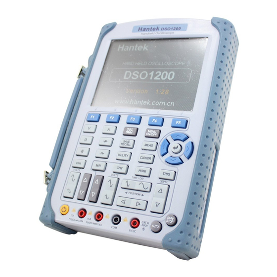
DSO1000 SERIES HANDHELD OSCILLOSOPE General Check When you have got a new DSO1000 series , it is suggested that you should perform a general inspection on the instrument according to the following steps: ■ Check the shipping container for damage: Keep the damaged shipping container or cushioning material until the contents of the shipment have been checked for completeness and the instrument has been checked mechanically and electrically. - Page 10 1060/1200/1600/1600H Figure 1-1 Front Panel...
- Page 11 DSO1000 SERIES HANDHELD OSCILLOSOPE Figure 1-2 Front Panel Description Description 1. LCD Display 2. F1~F5: Sets or switch options for the menu 3. Arrow Keys 4. HORI: Shows Horizontal menu 5. TRIG: Shows Trigger menu 6. LEVEL: Adjust the trigger level 7.
- Page 12 1060/1200/1600/1600H 9. TIME/DIV: Decrease or Increase the time base 10. POSITION: Adjust the horizontal trigger position 11. CH2: Shows the CH2 menu 12. VOLTS: Decrease or Increase the voltage/div 13. CH1: Shows the CH1 menu 14. M/R: Shows the Math or REF menu 15.
- Page 13 DSO1000 SERIES HANDHELD OSCILLOSOPE 2. Shows horizontal trigger time 3. Shows location of the current waveform in the memory 4. Shows the trigger position in the memory 5. Shows the trigger mode 6. Shows the trigger source 7. Shows the trigger level 8.
-
Page 14: Input Connections
1060/1200/1600/1600H Input Connections See the following Figure 1-4: Figure 1-4 Input Connections Description: 1. The power adapter is supplied for AC power supply and battery recharging. 2. Multi-meter input jacks, including four circular banana jacks .The four circular jacks are used for voltage,resistance,mA range current and A range current inputs. -
Page 15: Function Check
DSO1000 SERIES HANDHELD OSCILLOSOPE Function Check Perform this quick functional check to verify that your oscilloscope is operating correctly. 1. Turn on the instrument. Use the power adapter designed for your oscilloscope only. Use a power source that delivers 100 to 240 VACRMS, 50Hz. Turn on the oscilloscope. 2. -
Page 16: To Compensate Probes
1060/1200/1600/1600H To compensate probes Perform this adjustment to match the characteristics of the probe and the channel input. This should be performed whenever attaching a probe to any input channel the first time. CH1→Probe→10X 1. From CH1 menu, set the probe attenuation to 10X (press Set the switch to X10 on the probe and connect it to CH1 of the oscilloscope. -
Page 17: To Display A Signal Automatically
DSO1000 SERIES HANDHELD OSCILLOSOPE Under Compensated 3. If necessary, use a non-metallic tool to adjust the trimmer capacitor of the probe for the flattest square wave being displayed on the oscilloscope. 4. Repeat if necessary. WARNNING: To avoid electric shock while using the probe, be sure the perfection of the insulated cable, and do not touch the metallic portions of the probe head while it is connected with a voltage source. -
Page 18: Using The Ll Ll
1060/1200/1600/1600H Using the Oscilloscope This part provides a step-by-step introduction to the scope functions. The introduction does not cover all of the capabilities of the scope functions but gives basic examples to show how to use the menus and perform basic operations. - Page 19 DSO1000 SERIES HANDHELD OSCILLOSOPE Figure 1-7 The Menu MENU ON/OFF 1. Press the key to display the Function Menu on the bottom of the MENU ON/ screen and the corresponding optional settings on the bottom. Press again to hide the Function Menu. 2.
- Page 20 1060/1200/1600/1600H ■ button changes the time base in a 1-2-5 step sequence, and displays thevalue in the status bar. 2. Move signal horizontally. ■ button moves displayed signal horizontally on waveform window. It sets the trigger point position. Set up the trigger system 1.
-
Page 21: Chapter 2: Operating
DSO1000 SERIES HANDHELD OSCILLOSOPE CHAPTER 2: Operating Scope The end user should know how to determine the system setup from the status bar of a . This chapter will detail the function of the test tool. ■ Set Vertical System ■... -
Page 22: Set Vertical System
1060/1200/1600/1600H Set Vertical System Each channel of has its own independent operation menu and it will pop up after pressing CH1 or CH2 button. The settings of all items in the menu are shown in the table below. To make vertical CH1 and CH2 settings, do the following: 1. - Page 23 DSO1000 SERIES HANDHELD OSCILLOSOPE Figure 2-1 The CH1 Menu The following table describes the channel menu: Menu Setting Description Turn on Channel Enable Turn off Channel The dc component in the input signal is blocked Coupling The ac and dc components of the input signal are allowed Disconnect the input signal Select one according to the probe attenuation factor to Probe...
- Page 24 1060/1200/1600/1600H Turn on the BW Limit BW Limit Turn off the BW Limit 1. Change Volt/DIV It is the default setting of Volts/Div in a 1-2-5-step sequence from 1mV/div,2mV/div,5mV/ div or 10mV/div, 20mV/div, 50mV/div,..., to 1V/div,2 V/div,5 V/div. The Volt/DIV will be displayed in the status bar on the bottom of the screen.
- Page 25 DSO1000 SERIES HANDHELD OSCILLOSOPE Figure 2-3 Waveform Display Press CH1→Coupling→DC, to set “DC” coupling. It will pass both AC and DC components of the input signal. The waveform is displayed as Figure 2-4.
- Page 26 1060/1200/1600/1600H Figure 2-4 Waveform Display CH1→Coupling→GND Press , to set “GND” coupling, it disconnects the input signal. The screen displays as Figure 2-5:...
- Page 27 DSO1000 SERIES HANDHELD OSCILLOSOPE Figure 2-5 Waveform Display 3. Set Probe Attenuation allows adjusting the probe attenuation scale factor correspondingly in the channel operation menu in order to comply with the probe attenuation scale. The attenuation factor changes the vertical scaling of the so that the measurement results reflect the actual voltage levels at the probe tip.
- Page 28 1060/1200/1600/1600H 4. Invert a waveform The displayed waveform reverses 180 degrees relatively to the ground potential. CH1 or CH2 → F5 → F3 Invert. Press , to turn on/off the Figure 2-7 Turn Invert off...
- Page 29 DSO1000 SERIES HANDHELD OSCILLOSOPE Figure 2-8 Turn Invert on 5. Set Band-Width Limit With CH1 taken for example, input a signal containing high frequency component. Press CH1→F5→F4→OFF, to set up bandwidth limit to “OFF” status. The oscillosc ope is set to full bandwidth and passing the high frequency component in the signal. The waveform is displayed as Figure 2-9.
- Page 30 1060/1200/1600/1600H Figure 2-9 Turn BW limit Off Press CH1→F5→F4→ON, to set up bandwidth limit to “ON” status. It will reject the frequency component higher than 20MHz. Press CH1→F5→F5→F2→ON, to set up bandwidth limit to “ON” status. It will reject the frequency component higher than 100MHz.This function is not used in DSO1060.
- Page 31 DSO1000 SERIES HANDHELD OSCILLOSOPE Figure 2-10 Turn BW limit On 6. Math Setting The mathematic functions include “add”, “subtract”, “multiply”, “division”, and “FFT” for CH1 and CH2. The mathematic result can be measured by the grid and the cursor. The mathematic window is displayed as figure 2-11. The Math menu (Page 1/2) Figure 2-11 The Math menu The Math menu (Page 2/2)
- Page 32 1060/1200/1600/1600H Figure 2-12 The Math menu The Math menu setting table Menu Setting Description Turn on math Enable Turn off math A + B Add source A and source B A - B Subtract source B from source A Operate...
- Page 33 DSO1000 SERIES HANDHELD OSCILLOSOPE Figure 2-13 The multiplication 7. FFT The FFT (Fast Fourier Transform) process converts a time-domain signal into its frequency components mathematically. FFT waveforms are useful in the following applications: ■ Measure harmonic content and distortion in systems ■...
- Page 34 1060/1200/1600/1600H Figure 2-14 The FFT menu The FFT menu table Menu Setting Description Turn on FFT Enable Turn off FFT Operate Fast Fourier Transform Source Define CH1 or CH2 as FFT source Rectangle Hanning Window Select window for FFT Hamming...
- Page 35 DSO1000 SERIES HANDHELD OSCILLOSOPE measurement and the source signals characteristics to determine the window to use. Use the following guidelines to select the best window. The FFT Window table Window Features Best for measuring Best frequency resolution and Transients or bursts, the signal worst magnitude resolution.This levels before and after the is essentially the same as no...
- Page 36 1060/1200/1600/1600H Figure 2-15 The reference function window Internal M/R → REF → InternaI Press and go to the following menu. REF menu when using internal memory Figure 2-16 The Internal menu REF menu table when using internal memory Menu Setting...
- Page 37 DSO1000 SERIES HANDHELD OSCILLOSOPE Select memory location in scope Internal Location Select memory location out scope External Save REF waveform Save Load REF waveform Load REF menu table when using external memory Menu Setting Description Turn on REF Enable Turn off REF Select CH1 as REF channel Source Select CH2 as REF channel...
-
Page 38: Set Horizontal System
1060/1200/1600/1600H To load a chosen file Load Go to the Storage menu page Display a Reference Waveform Figure 2-19 Reference display 1. Press M/R button to show the reference waveform menu. 2. Press F2 to select the reference channel: CH1, CH2 or MATH. - Page 39 DSO1000 SERIES HANDHELD OSCILLOSOPE center. Horizontal position changes the displayed waveform position, relative to the trigger point. Press HORI button to show the horizontal system menu. The settings of this menu are listed in the following table. The Horizontal Menu Figure 2-20 The Horizontal menu The Horizontal Menu Table Menu...
- Page 40 1060/1200/1600/1600H Figure 2-23 The horizontal/Time base marks Marks Indicator 1. The current running status. 2. The trigger position in the memory. 3. The current waveform window’s position in the memory. 4. The trigger position in the current waveform window. 5. The horizontal time base (main time base).
- Page 41 DSO1000 SERIES HANDHELD OSCILLOSOPE Figure 2-24 ALT Mag Mode Description: 1. Wave to be horizontally expanded. 2.The magnified Wave. 3.The time base of ALT Mag. 4.The main time base. The following describes the ALT Mag display. The screen is divides into two parts. The upper half displays the main waveform window and the lower half displays an expanded portion of the main waveform window.This expanded portion of the main window is called the ALT Mag window.Two blocks shadow the upper half.
-
Page 42: Set Trigger System
1060/1200/1600/1600H horizontal axis (X) and CH2 in the vertical axis (Y) Figure 2-25 X-Y display format The following modes or functions will not work in X-Y format. ■ Automatic Measurements ■ Cursor Measurements ■ REF and MATH Operations ■ Horizontal Position ■... - Page 43 DSO1000 SERIES HANDHELD OSCILLOSOPE Trigger Modes provides four trigger modes: Edge, Pulse , Alternative and Video. Edge: An edge trigger occurs when the trigger input passes through a specified voltage level in the specified slope direction. Pulse : Use this trigger type to catch pulses with certain pulse width. Alternative : Trigger on non-synchronized signals.
- Page 44 1060/1200/1600/1600H Set the trigger level to the center of the signal Pulse Trigger Setting Pulse trigger occurs according to the width of pulse. The abnormal signals can be detected through setting up the pulse width condition. Press TRIG → F1 → Pulse button to show the pulse trigger menu as the following table.
- Page 45 DSO1000 SERIES HANDHELD OSCILLOSOPE The Pulse Trigger Table (Page 2/2) Menu Setting Description Back to the previous menu page Auto Acquire waveform even no trigger occurred Sweep Normal Acquire waveform when trigger occurred Single When trigger occurs, acquire one waveform and then stop Reject high frequency signals Reject Set the trigger level to the center of the signal...
- Page 46 1060/1200/1600/1600H Edge Type Set Edge/Pulse Trigger as the trigger type Pulse Rising Trigger on rising edge Slope Falling Trigger on falling edge Go to the next menu page Figure 2-29 ALT Mode Screen Description: 1. The trigger type of CH1 2.
- Page 47 DSO1000 SERIES HANDHELD OSCILLOSOPE 11. The trigger level of CH2 12. The trigger delay time of CH2 13.The CH1 Voltage/Div 14.The CH2 Voltage/Div Figure 2-31 The ALT Trigger menu The Alternative menu table (Type edge)(Page 2/2) Menu Setting Description Back to the previous menu page HF Reject Reject high frequency signals or not Set the trigger level to the center of the signal...
- Page 48 1060/1200/1600/1600H +More +Pulse width more than selecting pulse condition +Less +Pulse width less than selecting pulse condition +Equal +Pulse width equal to selecting pulse condition When -More -Pulse width more than selecting pulse condition -Less -Pulse width less than selecting pluse condition...
- Page 49 DSO1000 SERIES HANDHELD OSCILLOSOPE The Video Trigger menu (Page 2/2) Figure 2-34 The Video Tirgger menu The Video Trigger menu table Menu Setting Description Set trigger mode for CH1 Channel Set trigger mode for CH2 Applicable to the video signal of which the black level is Normal Polarity Applicable to the video signal of which the black level is...
-
Page 50: Save / Recall Waveforms And Setups
1060/1200/1600/1600H Force the oscilloscope to trigger in the absence condi- Auto Let oscilloscope to trigger in the suitable trigger condi- Sweep Normal Let osclloscope to trigger one time in the suitable trig- Single ger condition,then stop Back to the previous menu page Term interpretation ■... - Page 51 DSO1000 SERIES HANDHELD OSCILLOSOPE External Go to menu for external memory operation Wave The Wave menu Figure 2-35 The Wave menu The Wave menu table Menu Setting Description Internal Go to menu for internal memory operation External Go to menu for external memory operation Setup The Setup menu Figure 2-36 The Setup menu...
- Page 52 1060/1200/1600/1600H Figure 2-37 The Bitmap menu The Bitmap menu table Menu Setting Description External Go to menu for external memory operation The CSV menu Figure 2-38 The CSV menu The CSV menu table Menu Setting Description External Go to menu for external memory operation...
- Page 53 DSO1000 SERIES HANDHELD OSCILLOSOPE Load Recall factory setups or files Internal Memory SAVE/RECALL →Internal Press to go to the following menu Menu Setting Description Setup_01 Internal Set up the location of files in internal memory Setup_15 Recall waveform files and setup files from the Load internal memory location Save waveform files and setup files to the internal...
-
Page 54: Utility Function
1060/1200/1600/1600H Figure 2-40 File System Factory The oscilloscope has default settings and can be recalled at any time. Memory location Specify the memory location to save/recall the waveforms and setups. Load Recall saved waveforms, setups and default settings. Save Save waveforms and setups. - Page 55 DSO1000 SERIES HANDHELD OSCILLOSOPE Utility Utility Press the button to show the menu of the settings in the system. The series without RS232 and LAN: The Utility menu (Page 1/4) The Utility menu (Page 2/4) The Utility menu (Page 3/4) The Utility menu (Page 4/4) Figure 2-41 The Utility menu(without RS232 and LAN) The series with RS232 and LAN:...
- Page 56 1060/1200/1600/1600H The Utility menu (Page 3/5) The Utility menu (Page 4/5) The Utility menu (Page 5/5) Figure 2-42 The Utility menu (with RS232 and LAN) The Utility menu table (Page 1/4 and Page 1/5) Menu Setting Description Turn off Frequency or Counter...
- Page 57 DSO1000 SERIES HANDHELD OSCILLOSOPE Go to the next menu page The Utility menu table (Page 2/4 and Page 2/5) Menu Setting Description Back to the previous menu page Back to the previous menu page Pass/Fail Go to Pass/Fail menu page Record Go to Record menu page Select languages...
- Page 58 1060/1200/1600/1600H Go to the next menu page The Utility menu table (Page 4/4 and Page 4/5) Menu Setting Description Back to the previous menu page Back to the previous menu page Not save the system configuration when shut down No Save...
- Page 59 DSO1000 SERIES HANDHELD OSCILLOSOPE The calibration screen is shown as in Figure 2-43. Figure 2-43 The Calibration Screen Note: must have been working or warm-up at least 30-minutes before running calibration to get best accuracy. will calibrate parameter of vertical system (CH1, CH2). Pass/Fail The Pass/Fail function monitors changes of signals and output pass or fail signals by comparing the input signal is within the pre-defined mask.
- Page 60 1060/1200/1600/1600H Figure 2-44 The Pass/Fail menu The Pass/Fail menu (Page 2/2) Figure 2-45 The Pass/Fail menu The Pass/Fail menu table (Page 1/2) Menu Setting Description Turn on Pass/Fail test Enable Turn off Pass/Fail test Select Pass/Fail test on CH1 Source...
- Page 61 DSO1000 SERIES HANDHELD OSCILLOSOPE Utility→Pass/Fail→Mask Press Setting to go to the following menu. The Mask menu (Page 1/2) Figure 2-46 The Mask menu The Mask menu (Page 2/2) Figure 2-47 The Mask menu The Mask setting menu table (Page 1/2) Menu Setting Description...
- Page 62 1060/1200/1600/1600H Menu Setting Description Save Go to save menu (same as REF save menu) Load Recall mask setting file from external memory Waveform Recorder Waveform recorder records input waveforms from CH1 and CH2, with a maximum record length of 1000 frames.
- Page 63 DSO1000 SERIES HANDHELD OSCILLOSOPE Go to the next menu page The Record menu table (Record Mode) (Page 2/2) Menu Setting Description Back to the previous menu page Interval <10.0ms-20s> Set time interval between record frames Back to the Utility menu page Play : Play back the recorded waveforms.
- Page 64 1060/1200/1600/1600H Go to the next menu page The Record menu table (Play Mode) (Page 2/2) Menu Setting Description Back to the previous menu page Start Frame <1-1000> Set start frame Cur Frame <1-1000> Select current frame to be played End Frame <1-1000>...
-
Page 65: Signal Measurement
DSO1000 SERIES HANDHELD OSCILLOSOPE End Frame <1-1000> Set end frame to be saved Internal Location Set up Store location External Go to the next menu page The Record menu when the save to Internal memory (Storage Mode) (Page 2/2) Menu Setting Description Save... - Page 66 1060/1200/1600/1600H The Measure menu (Page 2/5) Figure 2-55 The Measure menu The Measure menu (Page 3/5) Figure 2-56 The Measure menu The Measure menu (Page 4/5) Figure 2-57 The Measure menu The Measure menu (Page 5/5) Figure 2-58 The Measue menu...
- Page 67 DSO1000 SERIES HANDHELD OSCILLOSOPE Select CH1 or CH2 as source Source channel for measurement Voltage Type Select to measure voltage parameter Time Turn on all measurement result Meas All Turn off all measurement result Clear Clear measurement result on screen Go to the next menu page The Voltage Measurement menu table Menu...
-
Page 68: Cursor Measurement
1060/1200/1600/1600H Frequency Reciprocal of the period of the first cycle in the waveform Period Time to take for the first signal cycle to complete in the waveform Rising The time taken from lower threshold to upper threshold Falling The time taken from upper threshold to lower threshold... - Page 69 DSO1000 SERIES HANDHELD OSCILLOSOPE Manual Set to Manual Mode Track Set to Track Mode Mode Auto Set to Auto Mode Turn off the cursor measure Shown as vertical line to measure the horizontal parameters Type Shown as horizontal line to measure the vertical parameters Source Select the measurement signal source...
- Page 70 1060/1200/1600/1600H Figure 2-60 The Automatic Cursor Mode 2. Manual Cursor Mode In this mode, the measures the Y or X coordinate increments between the two cursors. See figure 2-61. 1) Select menu Mode->Manual. 2) Select menu Type->X/Y to get the vertical or horizontal of Cursor A or Cursor B.
- Page 71 DSO1000 SERIES HANDHELD OSCILLOSOPE Figure 2-61 The Manual Cursor Mode 3. Track Cursor Mode In Track Cursor Mode, the Cursor A and Cursor B move together with the selected waveform. See figure 2-62.
-
Page 72: Io Set
1060/1200/1600/1600H Figure 2-62 Track Cursor Mode Please do the following steps: 1. Select menu Mode->Track. 2. Select Source for measurements. Select options as followings. Cursor A->CH1/CH2. Cursor B->CH1/CH2. 3. Select Cursor A or Cursor B. Move the Select Cursors to adjust the increments between the Cursors. - Page 73 DSO1000 SERIES HANDHELD OSCILLOSOPE Figure 2-63 The IO Set menu(LAN) The IO Set menu table(LAN) Menu Setting Description Setting Create a new LAN connection Go to the Utility menu page The IO Set menu(RS232) Figure 2-64 The IO Set menu(RS232) The IO Set menu table(RS232) Menu Setting...
- Page 74 1060/1200/1600/1600H Figure 2-65 the Lan Setting window Press the button F2 in the IO Set menu(RS232),you can modify Baud Rate value. See the IO Set menu (RS232) in Figure 2-64. Acquire When you acquire an analog signal, the oscilloscope will convert it into a digital one.
-
Page 75: Chapter 3 Using Examples
DSO1000 SERIES HANDHELD OSCILLOSOPE Chapter 3 Using examples Example 1: Simple Measurement To acquire and display a signal, please do the steps as followings: 1. Connect signal to CH1 by using probe. 2. Press the key AUTO on key panel. set the vertical, horizontal, and triggers controls at the best status automatically. - Page 76 1060/1200/1600/1600H Figure 3-1 The Vpp and Freq measurement Window Example 2: The Application of the X-Y Operation X-Y Plot acts to analyze correlation of data of two channels. Lissajous diagram is displayed in the screen when you use X-Y Plot,which enables to compare frequencies,amplitudes and phases of counterpart waveform against the reference waveform.
- Page 77 DSO1000 SERIES HANDHELD OSCILLOSOPE See Signal in X-Y Format in figure 3-2. Figure 3-2 Signal in X-Y Format Instruction of the Ellipse Method...
- Page 78 1060/1200/1600/1600H Sinθ = A/B or C/D, where θ = phase shift (in degrees) between the two signals. From the formula above: θ = ±arcsine (A/B) or ±arcsine (C/D) θ must be in the range of (0~π/2) or (3π/2~2π) if the main axis of the ellipse is between I and III quadrant, .
- Page 79 DSO1000 SERIES HANDHELD OSCILLOSOPE See the FFT Measurement (Cursor Type X) in figure 3-4. Figure 3-4 FFT Measurement (Cursor Type X) Example 4: The Pass/Fail Test The Pass/Fail Test is one of the enhanced special functions of the . By this function, the could compare the input signal with the established waveform mask.
- Page 80 1060/1200/1600/1600H See the Pass/Fail window in figure 3-5. Figure 3-5 The Pass/Fail Window Example 5: Reduce the noise on a signal See the signal with random noise in figure 3-6. To reduce random noise, do the following steps: 1. Set the Probe and the channel attenuations to “x10”.
- Page 81 DSO1000 SERIES HANDHELD OSCILLOSOPE See signal after reducing random noise in figure 3-7. Figure 3-6 Signal with random noise...
- Page 82 1060/1200/1600/1600H Figure 3-7 Signal afer reducing random noise Example 6: Capture a Single signal To capture a single event, it needs to gather some pre-test knowledge of the signal in order to set up the trigger level and slope correctly. For example, if the event is derived from TTL logic, a trigger level of 2 Volts should work on a rising edge.
-
Page 83: Chapter 4: Multimeter
DSO1000 SERIES HANDHELD OSCILLOSOPE CHAPTER 4: Multimeter About this chapter This chapter provides an introduction to the multimeter functions of DSO1000 Series. The introduction gives guides to show how to use the menus and perform basic measurements. Connecting the Meter Use the 4-mm safety banana jack inputs for the Meter functions: 10A , mA, COM,V/Ω/C. - Page 84 1060/1200/1600/1600H DC: Direct electric measurement AC: Alternating electric measurement 3)The symbol of Mutimeter current mode. 4) Manual/Auto range indictors, among which the MANUAL refers to measuring range in manual operation mode and Auto means the measuring range in automatic operation mode.
- Page 85 DSO1000 SERIES HANDHELD OSCILLOSOPE Figure 4-2 Resistance Measurement Making a Diode Measurement To make a measurement on the diode, do the following: 1) Press the diode key and a diode symbol appears at the top of the screen. 2) Insert the black lead into the COM banana jack input and the red lead into the V/Ω/C banana jack input.
- Page 86 1060/1200/1600/1600H Figure 4-3 Diode Measurement To perform an On-off test, do the following: 1) Press the On-off key and then On-off indictor appears on the top of the screen. 2) Insert the black lead into the COM banana jack input and the red lead into the V/Ω/C banana jack input.
- Page 87 DSO1000 SERIES HANDHELD OSCILLOSOPE Figure 4-4 On-off Measurement Making a Capacitance Measurement To measure a capacitance, do the following: 1) Press the C key and a capacitor symbol appears on the top of the screen. 2) Insert the black lead into the COM banana jack input and the red lead into the V/Ω/C banana jack input.
- Page 88 1060/1200/1600/1600H Figure 4-5 Capacitance Measurement Making a DC Voltage Measurement To measure a DC voltage, do the following: 1. Press the V key and DC appears at the top of the screen. 2. Insert the black lead into the COM banana jack input and the red lead into the V/Ω/C banana jack input.
- Page 89 DSO1000 SERIES HANDHELD OSCILLOSOPE Figure 4-6 DC voltage Measurement Making an AC Voltage Measurement To measure the AC voltage, do the following: 1) Press the V key and DC appears on the screen. 2) Press the F1 key and AC appears on the screen. 3) Insert the black lead into the COM banana jack input and the red lead into the V/Ω/C banana jack input.
- Page 90 1060/1200/1600/1600H Figure 4-7 AC voltage Measurement Making a DC Current Measurement To measure a DC current which is less than 600 mA , do the following: 1) Press the A key and then DC appears on the screen. The unit on the main reading screen is mA.
- Page 91 DSO1000 SERIES HANDHELD OSCILLOSOPE Figure 4-8 DC current Measurement for 600 mA To measure a DC current which is larger than 600 mA, do the following: 1) Press the A key and then DC appears on the screen. The unit on the main reading screen is mA.
- Page 92 1060/1200/1600/1600H Figure 4-9 DC Current Measurement for 10A Making an AC Current Measurement To measure an AC current which is less than 600 mA, do the following: 1) Press the A key and then DC appears on the screen. The unit on the main reading screen is mA,and mA will display on the bottom of the screen, press F2 to switch the measurement between mA and 10A.
- Page 93 DSO1000 SERIES HANDHELD OSCILLOSOPE Figure 4-10 AC Current Measurement for 600 mA To measure an AC current which is larger than 600 mA, do the following: 1) Press the A key and then DC appears on the screen. The unit on the main reading screen is mA.
- Page 94 1060/1200/1600/1600H Figure 4-11 AC Current Measurement for 10A Taking a Relative Measurement A currently measured result relative to the defined reference value is displayed in a rela- tive measurement. The following example shows how to take a relative measurement. At first, it is required to acquire a reference value.
- Page 95 DSO1000 SERIES HANDHELD OSCILLOSOPE Figure 4-12 Relative Measurement Selecting Automatic/Manual Range Adjustment The default range mode of the instrument is automatic range. Suppose you are using the DC voltage mode, to switch to the manual range, perform the following steps: 1) Press F3 key to enter the manual range mode and then Manual is displayed on the top of the screen.
- Page 96 1060/1200/1600/1600H Figure 4-13 The Manual Range Mode...
-
Page 97: Chapter 5: Troubleshooting
DSO1000 SERIES HANDHELD OSCILLOSOPE Chapter 5: Troubleshooting 1.The oscilloscope cannot start. 1) Check the power cable connection. 2) Ensure the power switch is turned on. 3) After the above inspection, restart the oscilloscope. 4) If the problem still remains, please contact us for help. 2. -
Page 98: Chapter 6: Specifications
1060/1200/1600/1600H Chapter 6: Specifications Vertical Channels DSO1060: 60MHz DSO1200: 200MHz Bandwidth DSO1600: 600MHz DSO1600H: 600MHz DSO1060: 5.8ns DSO1200: 1.7ns Rise Time DSO1600: 0.58ns DSO1600H: 0.58ns Input Impedance Resistance: 1M;Capacitance: 15pF DSO1060: 10mv/div to 5v/div DSO1200: 10mv/div to 5v/div Input Sensitivity... - Page 99 DSO1000 SERIES HANDHELD OSCILLOSOPE Source CH1,CH2 Mode Edge, Pulse Width, Alternative, Video. X-Y Mode X-Axis Input Y-Axis Input Phrase Shift Max.3 degree Cursors and Measurement Vpp,Vamp,Vmax,Vmin,Vtop,Vmid,VbaseVpp,Vamp,Vmax,Vmin,Vtop,Vmi Voltage d,Vbase,Vavg,Vrms,Vcrms,Preshoot,Overshoot Frequency,Period,Rise time,Fall Time,Positive Width,Negative Width,Duty Time Cycle Delay Delay 1->2↑, Delay 1-2↓ Cursor Manual,Track,Auto Measure Modes Math...
- Page 100 1060/1200/1600/1600H Range Accuracy Resolution 60.00mV(manual) 10uV 600.0mV 100uV 6.000V DC Voltage ±1%±1digit 60.00V 10mV 600.0V 100mV 800V 60.00mV(manual) 10uV 600.0mV(manual) 100uV AC Voltage 6.000V ±1%±3digit 60.00V 10mV 600.0V 100mV 60.00mA 10uA ±1.5%±1digit 600.0mA ±1%±1digit 100uA DC Current 6.000A ±1.5%±3digit 10.00A 10mA 60.00mA...
- Page 101 DSO1000 SERIES HANDHELD OSCILLOSOPE Range Accuracy Resolution On-off Test < 10 Ω Display TFT LCD Type 5.7 Inch width LED Backlight Display Display Resolution 240 (Vertical) X 320 (Horizontal) pixels Interface USB 2.0 Optional RS232,LAN Power Source AC 100V ~ 240V, 50Hz ~ 60Hz; Line Voltage Range DC Input:8.5VDC,1500mA Battery Power(Installed)
-
Page 102: Chapter 7: Appendix
1060/1200/1600/1600H Chapter 7: Appendix Appendix A: Accessories 1) Probe×2 (1.2m), 1:1, (10:1) Passive Probes 2) A Power Adapter that fits the standard of destination country 3) A User’s Guide 4) A User Registration Form 5) A User Warranty Card 6) A Software CD Appendix B: Warranty We warrant our products’... - Page 103 DSO1000 SERIES HANDHELD OSCILLOSOPE before storage. Charging the The lithium battery is possibly not charged when delivery. To make the battery with enough electric quantity, it must be charged for 4 hours (the test tool must be turned off during charging). The battery can supply power for 6 hours after being charged com- pletely.
- Page 104 1060/1200/1600/1600H...
Need help?
Do you have a question about the 1060 and is the answer not in the manual?
Questions and answers