Sign In
Upload
Download
Table of Contents
Contents
Add to my manuals
Delete from my manuals
Share
URL of this page:
HTML Link:
Bookmark this page
Add
Manual will be automatically added to "My Manuals"
Print this page
×
Bookmark added
×
Added to my manuals
Manuals
Brands
Hantek Manuals
Test Equipment
DSO1000E Series
User manual
Hantek DSO1000E Series User Manual
Handheld oscilloscope
Hide thumbs
1
Table Of Contents
2
3
4
5
6
7
8
9
10
11
12
13
14
15
16
17
18
19
20
21
22
23
24
25
26
27
28
29
30
31
32
33
34
35
36
37
38
39
40
41
42
43
44
45
46
47
48
49
50
51
52
53
54
55
56
57
58
59
60
61
62
63
64
65
66
67
68
69
70
71
72
73
74
75
76
77
78
79
80
81
82
83
84
85
86
87
88
89
90
page
of
90
Go
/
90
Contents
Table of Contents
Troubleshooting
Bookmarks
Table of Contents
Table of Contents
Copyright Declaration
Chapter 1 Safety Tips
General Safety Summary
Safety Terms and Symbols
Terms on Product
Symbols on Product
Product Scrapping
Chapter 2 Overview
Brief Introduction to DSO1000E Series
Help System
Chapter 3 Getting Started Guide
Installation
Functional Check
Power on the Oscilloscope
Connect the Oscilloscope
Observe the Waveform
Probe Examination
Safety
Use of Probe Check Wizard
Manual Probe Compensation
Probe Attenuation Setting
Self Calibration
Chapter 4 Main Feature Description
Oscilloscope Setup
Trigger
Data Acquisition
Waveform Scaling and Positioning
Waveform Measurement
Chapter 5 Basic Operation
Displayarea
XY Format
Horizontal Controls
Scan Mode Display (Roll Mode)
Vertical Controls
Math FFT
Trigger Controls
Menu and Option Buttons
Save/Recall
Measure
Utility
Display
Acquire
Cursor
Fast Action Buttons
Autoset
Signal Connectors
Chapter 6 Application Examples
Example 1: Taking Simple Measurements
Example 2: Taking Cursor Measurements
Example 3: Analyzing Input Signals to Eliminate Random Noise
Example 4: Capturing Single-Shot Signal
Example 5: Using X-Y Mode
Example 6: Triggering on Pulse Width
Example 7: Triggering on Video Signal
Example 8: Using Slope Trigger to Capture Particular Slope Signal
Example 9: Using Overtime Trigger to Measure Long Pulse Signal
Example 10: Using Math Functions to Analyze Waveforms
Example 11: Measuring Data Propagation Delay
Example 12: Back Light Control
Example 13: Auto Shut down
Example 14: Connect with PC Via Lan(Optional
Example 15: Charging
Chapter 7 Multimeter
Chapter 8 Recorder
Multimeter Trend
Oscilloscope Trend
Waveform Recorder
Chapter 9 Troubleshooting
Problem Settlement
Chapter 10 Specifications
Technical Specifications
Accessories
Chapter 11 General Care and Cleaning
General Care
Cleaning
Chapter 12 Services and Support
Advertisement
Quick Links
Download this manual
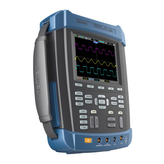
DSO1000E SERIES
HANDHELD OSCILLOSCOPE
USER'S MANUAL
1072E/1102E/1152E/1202E
(V1.0.1)
Table of
Contents
Previous
Page
Next
Page
1
2
3
4
5
Advertisement
Table of Contents
Need help?
Do you have a question about the DSO1000E Series and is the answer not in the manual?
Ask a question
Questions and answers
Related Manuals for Hantek DSO1000E Series
Test Equipment Hantek DSO 1062B User Manual
Handheld oscilloscope (81 pages)
Test Equipment Hantek DSO1000B Series User Manual
Handheld oscilloscope (84 pages)
Test Equipment Hantek 1060 User Manual
Dso1000 series, handheld oscilloscope (104 pages)
Test Equipment Hantek DSO1000S Series User Manual
Handheld oscilloscope (86 pages)
Test Equipment Hantek DSO1072E User Manual
Handheld oscilloscope (90 pages)
Test Equipment Hantek DSO1102E User Manual
Handheld oscilloscope (90 pages)
Test Equipment Hantek DSO1202E User Manual
Handheld oscilloscope (90 pages)
Test Equipment Hantek DSO1202BV User Manual
Handheld oscilloscope (84 pages)
Test Equipment Hantek DSO-1102 USB User Manual
(77 pages)
Test Equipment Hantek DSO5102P User Manual
100mhz 2 channel digital storage oscilloscope (72 pages)
Test Equipment Hantek DSO5000P Series User Manual
Digital storage oscilloscope (71 pages)
Test Equipment Hantek DSO8072E User Manual
Dso8000e series handheld oscilloscope (115 pages)
Test Equipment Hantek DSO2000 Series User Manual
Digital storage oscilloscope (72 pages)
Test Equipment Hantek DSO2000 Series User Manual
(72 pages)
Test Equipment Hantek DSO5202P User Manual
Digital storage oscilloscope (71 pages)
Test Equipment Hantek DSO-5200A User Manual
Usb pc based digital oscilloscope (18 pages)
This manual is also suitable for:
Dso1072e
Dso1102e
Dso1152e
Dso1202e
1072e
1102e
...
Show all
1152e
1202e
Table of Contents
Print
Rename the bookmark
Delete bookmark?
Delete from my manuals?
Login
Sign In
OR
Sign in with Facebook
Sign in with Google
Upload manual
Upload from disk
Upload from URL


Need help?
Do you have a question about the DSO1000E Series and is the answer not in the manual?
Questions and answers