
Related Manuals for Hantek HT824


Summary of Contents for Hantek HT824
- Page 1 USER’S MANUAL HT824 Multifunction Process Calibrator V1.0.0 http://www.hantek.com USER’S MANUAL...
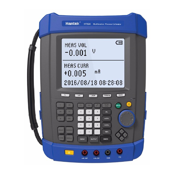
- Page 2 Introduction HT824 Multifunction Process Calibrator is handheld equipment with High-capacity rechargeable battery power supply. It can measurement or output a variety of electrical signal, and measurement or simulate a variety of TC and RTD. HT824 process calibrator also has following features: 1.The display has two parts.
-
Page 3: Safety Information
Other function Step output, slope output, save and recall data, USB communication, etc. Safety Information Process calibrator is designed according to international standard IEC1010-1, 1010.1-92 standard of international safety specification design and manufacture. User should use the calibrator as the instructions of this manual. Otherwise, the protection provided by the calibrator might be damaged. - Page 4 If the calibrator is abnormal, please do not use it. The protective measures might be destroyed. If any doubt, send it for repair. Never use the calibrator around the explosive gas, steam or dirt. Do not let the calibrator explore to strong light, high temperature or humid place.
- Page 5 The following table is the wiring instructions of port function. Remarks Name Instruction V/Ω、COM port Bottom The port to test or output voltage, millivolt, resistance and RTD. Bottom 1. The input port to test resistance or RTD third & fourth mA+/3W、mA-/4W port wire.
- Page 6 Instruction Key Name Choose voltage measurement function, and show the value in the upper part of screen. Use V/LOOP, COM port to input. Choose current measurement function, and show the value in the upper part of screen. Use mA, COM port to input. Start the loop power supply to test current, show the value in the upper LOOP part of screen.
- Page 7 Choose millivolt function (in the bottom of screen), the screen shows “mV” correspondingly. Switch measurement or output through “MEAS” and “SOURCE” keys. Choose TC (thermoelectric couple) function (in the bottom of screen), the screen shows “TC” correspondingly. Switch measurement or output through “MEAS”...
-
Page 8: Basic Operation
Remove the input data CLEAR Press this key in output mode, it will callout the setting value 0% from the memory and shows output. Press “0%” key and “ENTER” key together, it will save current output volume as 0% value. Press this key in output mode, it will increase output 25% of the range -25% from 0% to 100%. - Page 9 3) Press CONFIG, enter into the next level setting. Press EXIT to exit configuration menu. Setting 2. Adjusting screen contrast. Factory default is 09. The detail operation step and explanation are as follow. 1) Press CONFIG, keep pressing and select setting 2. It shows “Screen contrast XX” in the upper part of screen.
- Page 10 be changed. 3) Press CONFIG, enter into the next level setting. Press EXIT to exit configuration menu. Setting 6.Setting HART. The factory default is OFF. The detail operation step and explanation are as follow. 1) Press CONFIG, keep pressing and select setting 6. It shows “Setting HART: OFF (ON)”...
- Page 11 setting: OFF (ON)” in the upper part of screen. 2) Press up or down direction key, to select ON or OFF circularly. If select “ON”, turn on the system calibration. Otherwise, turn off the system calibration. 3) Press CONFIG, enter into the next level setting. Press EXIT to exit configuration menu.
-
Page 12: Measurement Functions
4) Press EXIT, exit the data recall function. 3、 Back light of screen Press BL, turn on the back light. It will automatically turn off after the appointed delay time or press BL again to turn it off. The delay time can be set, the default value is 5 minutes. - Page 13 transmitter and measure the current output of transmitter after the wiring is removed in site. If to use LOOP to measure current, please operate as following steps. ① Press LOOP(3) when the calibrator is in other measurement mode, it shows “LOOP” in the upper part of screen. Then the calibrator provides 24V loop power supply internally.
Need help?
Do you have a question about the HT824 and is the answer not in the manual?
Questions and answers