
Related Manuals for GE Medical Systems Solar 9500


Summary of Contents for GE Medical Systems Solar 9500
- Page 1 Solar 9500 ® Information Monitor Service Manual Software Version 3 2001085-061 Revision A...
- Page 2 Systems Information Technologies registered in the United States Patent and Trademark Office. All other trademarks contained herein are the property of their respective owners. © GE Medical Systems Information Technologies, 2003. All rights reserved. Solar 9500 Information Monitor Revision A...
-
Page 3: Table Of Contents
The Solar 9500 Information Monitor ........ - Page 4 Alternate Power Down Method ........3-27 Solar 9500 Information Monitor...
- Page 5 Calibration Completion ..........5-11 Revision A Solar 9500 Information Monitor 2001085-061...
- Page 6 Cleaning Inside the Solar 9500 CPU ........
- Page 7 Navigating Multi-page Output ........7-21 Revision A Solar 9500 Information Monitor 2001085-061...
- Page 8 Power Supply Assembly 419080-001B ....... . . 9-22 Solar 9500 Information Monitor...
-
Page 9: Introduction
Introduction Revision A Solar 9500 Information Monitor 2001085-061... -
Page 10: Manual Information
See the operator’s manual for the instructions necessary to operate the equipment safely in accordance with its function and intended use. Intended Audience This manual is intended for service representatives and technical personnel who maintain, troubleshoot, or repair this equipment. Solar 9500 Information Monitor Revision A 2001085-061... -
Page 11: Safety Information
Introduction: Safety Information Safety Information Responsibility of the Manufacturer GE Medical Systems Information Technologies is responsible for the effects of safety, reliability, and performance only if: Assembly operations, extensions, readjustments, modifications, or repairs are carried out by persons authorized by GE. -
Page 12: Warnings, Cautions, And Notes
CAUTION indicates a potential hazard or unsafe practice which, if not avoided, could result in minor personal injury or product/property damage. NOTE provides application tips or other useful information to assure that you get the most from your equipment. Solar 9500 Information Monitor Revision A 2001085-061... -
Page 13: Equipment Symbols
Power; = ON; = OFF Fuse PRESS Press to open. Medical Equipment With respect to electric shock, fire and mechanical hazards only in accordance with UL 2601-1, and CAN/CSA C22.2 NO. 601.1. 4P41 Revision A Solar 9500 Information Monitor 2001085-061... -
Page 14: Service Information
Regular maintenance, irrespective of usage, is essential to ensure that the equipment will always be functional when required. Equipment Identification Every GE Medical Systems Information Technologies device has a unique serial number for identification. A sample of the information found on a serial number label is shown below. -
Page 15: Overview
Overview Revision A Solar 9500 Information Monitor 2001085-061... -
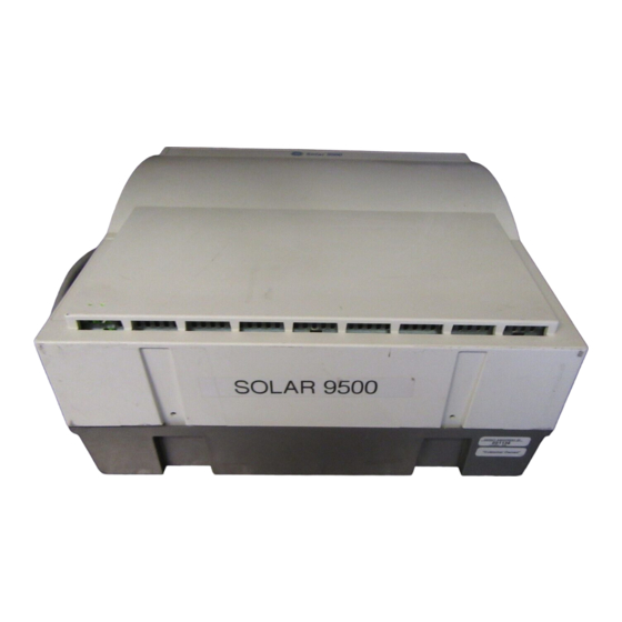
Page 16: The Solar 9500 Information Monitor
001A Up to two additional displays may be attached directly to the Solar 9500 Information Monitor to display layout configurations separate from the Primary Display. The additional displays are connected via optional video boards installed in the Solar 9500 processing unit. -
Page 17: Front View
Located at the rear of the unit are the equipotential lug, power supply inlet and switch, and a mounting bracket. &$87,21 The Solar 9500 processor must be mounted in the vertical position. Never operate the unit in the horizontal position. -
Page 18: Interconnection
(Parameter waveforms and numerics) between GE devices. UNITY NETWORK IX NETWORK is the Unity Network connection that provides non-real time data between the Solar 9500 system and other hospital intranet devices. TRAM-NET is the GE acquisition network connection that provides real time data between a Tram-rac’s patient connected acquisition... -
Page 19: Technical Specifications
Horizontal Frequency 57 kHz (minimum) Video bandwidth 110 MHz (minimum) Linearity 1.5% of vertical height Max Solar 9500 Features and Options Item Description User interface SAW Touchscreen (ELO touch systems SMART SET compatible) Waveform presentation Non-scrolling (erase bar) or scrolling... - Page 20 Description Power Requirements 110 - 120 (± 10%), 50/60-Hz 220-240 (± 10%), 50/60-Hz Power Consumption 200 Watts (includes Solar 9500, Tram-rac and Tram) Thermal dissipation 683 Btu/hr Internal 10 watt-hour UPS Provides 12 second backup power for clean disk shutdown...
- Page 21 Humidity 15% to 85% (noncondensing) Storage Conditions Temperature –40° C to 70° C (-40° F to 158° F) Humidity 15% to 95% (non-condensing) Physical Specifications (Solar 9500 CPU) Item Description Height 332 mm (13.0 in) Width 348 mm (13.7 in) Depth 156 mm (6.1 in)
- Page 22 Method(s) of sterilization or Not Applicable disinfection recommended by the manufacturer Mode of operation Continuous operation Solar 9500 Information Monitor Revision A 2001085-061...
-
Page 23: Supported Devices
Overview: Supported Devices Supported Devices The following is a list of supported peripheral devices compatible with the Solar 9500 via the Unity Network ID connectivity device. Refer to the Unity Network ID connectivity device service manual for interface adapter part numbers. - Page 24 Dräger Medical Babylog 8000 Evita Evita 2 Evita 2 Dura Evita 4 Hamilton Medical Amadeus Veolar Galileo Nellcor Puritan Bennett 7200E/SPE/AE Adult Star/1500/2000 Infant Star/500/950 Siemens Medical SV 300 SV 300A SV 900C/D/E 2-10 Solar 9500 Information Monitor Revision A 2001085-061...
-
Page 25: Installation
Installation Revision A Solar 9500 Information Monitor 2001085-061... -
Page 26: System Components
Additional single or dual parameter modules, RAMS, One or two additional displays, Unity Network ID PostScript Printer and/or PRN 50 or PRN 50-M, and a Browser server Shown below is an example of a Solar 9500 Information Monitoring System. SOLAR 9500 INFORMATION MONITORING SYSTEM TRAM-RAC... -
Page 27: Processing Unit Setup
Processing Unit Setup Check the unit for proper voltage setting before installation. Although the AC mains voltage on Solar 9500 processing unit is factory set for your requirements, the power supply could be damaged if S1 is in the wrong position. -
Page 28: Mounting
The processing unit MUST be installed in a vertical position with the supplied bracket before use. &$87,21 Operating the device in a horizontal position or without the supplied bracket may cause damage to the equipment. Wall channel 009B Solar 9500 Information Monitor Revision A 2001085-061... -
Page 29: Installing Cable Shroud
Do not force the cover. Ensure that the front cover is aligned properly on its hinges before closing. Forcing the front cover into place with improper alignment will cause damage to the cover. Revision A Solar 9500 Information Monitor 2001085-061... -
Page 30: Display Descriptions
Installation: Display Descriptions Display Descriptions A single Solar 9500 processing unit can be connected to up to three displays as shown in the block diagram below and described as follows: 011A Primary Display This is the first in a series of monitors or may be the sole monitor connected to the Solar 9500 processing unit. -
Page 31: Touchscreen Interface
The base Solar 9500 system only supports non-scrolling waveforms. For scrolling and non-scrolling waveform capability, the PCI bus add-in video board must be ordered. The Solar 9500 can support up to two add-in video boards. Browser Support... -
Page 32: Processing Unit/Display Interconnection
Installation: Processing Unit/Display Interconnection Processing Unit/Display Interconnection Each display in a Solar 9500 system must be connected according to its configuration. Illustrated below are simplified interconnect diagrams for the various display configurations. Two Displays - Primary Non-Scrolling Three Displays - Primary Non-Scrolling... -
Page 33: Flat Panel Display Interconnection
Use GE or approved display mounting solutions when installing one or more displays. &$87,21 When using a non-UL2601/IEC60601 display ALWAYS Š use an approved isolation transformer, and Š protect the display from possible ingress of liquids. Revision A Solar 9500 Information Monitor 2001085-061... -
Page 34: Acquisition Interfaces
Tram-rac 4A housing, which can hold a Tram module, a SAM module, and/or additional single parameter modules. 127( The Solar 9500 is NOT compatible with the RAC 2A housing. Shown below is a Tram-rac 4A housing with a Tram module and two single parameter modules inserted. -
Page 35: Tram-Rac Power Supply Connection
015A Processing Unit/Tram-rac Interconnection The Solar 9500 processing unit will support up to two Tram-rac housings. These housings can be connected in parallel or series. When connected in series the center Tram-net connector of the Tram-rac connects to the second Tram-rac housing. The Tram-rac housing furthest from the monitor must have a power supply. -
Page 36: Tram-Rac 4A Housing
9500 processing unit. 700520-00X 017B Unity Network ID Connectivity Device Shown below is a connection from the Unity Network ID to a Solar 9500 processing unit. The Unity Network ID may be connected to any M-Port. 104A 3-12 Solar 9500 Information Monitor... -
Page 37: Dual Tram-Rac Housings
Installation: Acquisition Interfaces Dual Tram-rac Housings Shown below are examples of how to connect two Tram-rac housings to a Solar 9500 information processor. NOTE WHEN CONNECTED IN PARALLEL, THE UNPOWERED RAC-4A MAY BE SUBSTITUTED BY A RAC-2 700520-00X 018B Parallel Connection... -
Page 38: About Tram-Net
The hub controls all of the data ‘traffic’ in the system. In a Tram-net system, the head hub is contained in the patient monitor, but there will be intermediate hubs in the Tram-rac housing and Tram module as well. 3-14 Solar 9500 Information Monitor Revision A 2001085-061... -
Page 39: Processing Unit/Rams Interconnection
Installation: Acquisition Interfaces Processing Unit/RAMS Interconnection Before connecting the RAMS to the Solar 9500 processing unit you must first configure the serial channel of the processing unit via the Serial Interface Controls in the Service Menu. See chapter 4, Serial Interface Controls for details. -
Page 40: Processing Unit/Polled Parameter Interconnection
Serial Interface Controls in the Service Menu. Refer to chapter 4, Serial Interface Controls for details. The serial port of the Solar 9500 has a standard PC pinout and functions as a DTE (see EIA-232-E and EIA/TIA-574 standards for further information). -
Page 41: Local Area Network (Lan) Interfaces
GE equipment throughout the hospital. Depending on the construction of the hospital, thick-net, thin-net, or CAT-5 twisted pair cabling is used. The Solar 9500 is designed to be used with twisted- pair cabling. Consult GE when trying to interface with either thick-net or thin-net cabling. -
Page 42: Twisted Pair
ICU (one segment) with the CCU (the other segment), information can pass between any of the nodes (patient monitors and central stations) on either branch similar to a patient transfer from one unit to another. 023A 3-18 Solar 9500 Information Monitor Revision A 2001085-061... -
Page 43: Network Terms
Installation: Local Area Network (LAN) Interfaces Network Terms Illustrated below is a simplified view of a network and a definition of its terms. 024A Revision A Solar 9500 Information Monitor 3-19 2001085-061... -
Page 44: Printer Interconnect
Only one PRN 50 or PRN 50-M writer can be used. ‹ A PRN 50 or PRN 50-M writer assigned to an M-Port will not be used by the Solar 9500 if a serial port is configured to be used for a PRN 50 or PRN 50-M writer. ‹... - Page 45 Installation: Printer Interconnect All printers are shared across the network whether they are directly connected to the network or indirectly through a Solar 9500 with a parallel port printer. This is accomplished by assigning a Solar 9500 to act as the print server for each printer on the network. A single Solar 9500 can act as a print server for multiple printers.
-
Page 46: Prn 50 Digital Writer
A PRN 50 or PRN 50-M digital writer can be connected to one of the Solar 9500 M-Ports or serial ports. A writer connected to an M-Port will not be used by the Solar 9500 if a writer is configured to a serial port. Cable PN 418335-001... -
Page 47: Connecting To The Unity Network Mc Network
126.50.x.x. and the netmask should be 255.0.0.0. This assumes that the default MC network address of the Solar 9500 is unchanged from the factory default. Consult the operating manual of the printer for setting the IP address and netmask. -
Page 48: Connecting To The Unity Network Ix Network
9500s must also be connected to the MC network, since all printer status information passes through the MC network. NETWORK 10 BASE-T PRINT SERVER IX NETWORK PORT NETWORK PORT MC NETWORK MC NETWORK PORT PORT UNITY NETWORK MC NETWORK 028A 3-24 Solar 9500 Information Monitor Revision A 2001085-061... -
Page 49: Keyboard And Mouse
KEYBOARD MOUSE 029B 127( The keyboard and mouse must be connected to the Solar 9500 processor BEFORE power up or it will not function. The keyboard will not operate unless the mouse is connected. Revision A Solar 9500 Information Monitor... -
Page 50: Turning Power On
Installation: Turning Power On Turning Power On The Solar 9500 processing unit is preset at the factory for a specific AC voltage. Before applying power to the monitor, be sure its voltage setting matches your power requirements. Refer to the label on the back of the processor for the voltage and current requirements. -
Page 51: Turning Power Off
Installation: Turning Power Off Turning Power Off The preferred method of turning on the Solar 9500 power off is to first shut the system down by using the on-screen menu command, then use the on/off mains power switch located on the back of the unit. - Page 52 Installation: Turning Power Off For your notes 3-28 Solar 9500 Information Monitor Revision A 2001085-061...
-
Page 53: Software Configuration
Software Configuration Revision A Solar 9500 Information Monitor 2001085-061... -
Page 54: Monitor Service Menu
Software Configuration: Monitor Service Menu Monitor Service Menu The Service Menu is for use by qualified field engineers and factory service personnel to configure and service the Solar 9500 Information Monitor. &$87,21 The Service Menu is intended for use only by qualified personnel. -
Page 55: Layout Controls
Configuration editing uses a number of windows to help you design your screen. These windows are combined and layered to maximize functionality and to permit you to configure the Solar 9500 according to your personal preference. Configuration editing functions are addressed in greater detail later in this chapter. -
Page 56: Display/Layout Setup
Primary, Secondary or Apps Only. The column labeled Motherboard Main refers to the graphics port on the Solar 9500 motherboard. The column Video Slot A refers to the first add-in video card, the column Video Slot B refers to the second add-in video card. - Page 57 The primary display is the first in a series of monitors or the sole monitor connected to the Solar 9500 processing unit. It is distinguished from the other monitors by the eight control buttons displayed at the bottom of the screen.
- Page 58 Motherboard Main connection. For scrolling and non-scrolling waveform capability, the PCI bus add-in video board must be ordered. The Solar 9500 can support up to two add-in video boards. (Slot A and B.) Waveform Options Scrolling refers to the ability to continuously move the waveforms across the display.
-
Page 59: Unit Defaults
Parameter menus accessed from the main menu, display “Control” in the upper-right corner whereas they display “Defaults” via the service menu. For example, “ECG Control” vs. “ECG Defaults.” Revision A Solar 9500 Information Monitor 2001085-061... - Page 60 O2 compensation. Alarm Defaults To set alarm defaults, select a parameter from the Setup Parameter Defaults window, then select To Alarm Setup... The Alarm Defaults window displays (see next page). 035A Solar 9500 Information Monitor Revision A 2001085-061...
- Page 61 Crisis, Warning, Advisory or Message. System Alarm Levels... Select System Alarm Levels... to open the System Alarm Defaults window. Set ECG Leads Fail and SpO2 Probe Off Patient to System Warning or System Advisory. Revision A Solar 9500 Information Monitor 2001085-061...
- Page 62 Print – Select Print to initiate a printout of the saved user default settings for all of the available parameters. GE Medical Systems Information Technologies recommends printing default settings after making changes. Close – Select Close to close the Setup Parameter Defaults window.
- Page 63 Select End Case... to set the default behavior when the End Case... button is selected. 038A Patient Info... Select Patient Info... to set the default units of measure for patient information. 039A Revision A Solar 9500 Information Monitor 4-11 2001085-061...
-
Page 64: Printing
Software Configuration: Monitor Service Menu Printing Patient data on the Solar 9500 can be printed for review to a PostScript compatible printer or writer. The Solar 9500 supports both parallel and network printers. A network printer shares the network with other Solar 9500 monitors. - Page 65 Revision page. It may take up to 5 minutes before the printer name(s) are displayed in the Network Printers window. Clear Print Queue... Select Clear Print Queue... to remove data waiting to be printed to a printer. The following confirmation screen displays. 041A Revision A Solar 9500 Information Monitor 4-13 2001085-061...
-
Page 66: Controls And Menu Timeouts
Select Change Timeouts... to set the length of time a pop-up window stays open. The choices are 15 seconds, 30 seconds, 1 minute and No Timeout. 127( Service related windows do not time out. 042A 4-14 Solar 9500 Information Monitor Revision A 2001085-061... -
Page 67: Module Calibration
Name or on to Hide Keyboard. (You can also put the cursor in either field by touching the screen.) When complete, select Ok to close the window and save the changes or select Cancel to close the window without saving. Revision A Solar 9500 Information Monitor 4-15 2001085-061... -
Page 68: Serial Interface Controls
127( If the serial port is configured for a writer, a PRN 50 or PRN 50-M connected to an M-Port will not be recognized by the Solar 9500. Patient data (Trends, Arrhythmia Review, Alarm History, etc.), Procedures (CO, PA, Wedge, 12SL, etc.) and System information (error logs, etc.) are not supported on a writer. -
Page 69: Network Services
Software Configuration: Monitor Service Menu Network Services The Solar 9500 system uses the Unity Network to send Layouts, Parameters and Alarm defaults, and Solar 9500 software to other Solar 9500 beds in the same care unit or other care units on the network. -
Page 70: Ip Address
When changing the IP address, make sure no other equipment on the network has the same address. When connected to the network the Solar 9500 will warn the user if duplicate IP addresses have been assigned. 046B... - Page 71 255.255.255.0 255.255.255.0 About Netmasks The variable netmask capability of the Solar 9500 allows for an advanced network with intelligent routers. Typically for the Unity Network MC network the netmask should be 255.0.0.0. For the Unity Network IX network the netmask should be set to match the rules for subnet segments as defined by the institution’s network topology.
-
Page 72: Time And Date
Select Current Time to reset the time based on the current time of the system clock. Select OK to display the message, “Press ‘Change’ to change the time. Press ‘Cancel’ to ignore the time change.” Select Cancel to exit without saving. 4-20 Solar 9500 Information Monitor Revision A 2001085-061... -
Page 73: Audio
4. Select Close to end test and close the window. Diagnostic Messages Under Diagnostic Messages you can display and print all system and Tram Log Files. See chapter 7, Troubleshooting for more information. Revision A Solar 9500 Information Monitor 4-21 2001085-061... -
Page 74: Locale Settings
1. Select Locale... The following window appears. 050A 2. Select a language and/or country, then click OK. A dialog box similar to the following appears: 051A 3. Select Yes. The Solar 9500 restarts in the new language. 4-22 Solar 9500 Information Monitor Revision A 2001085-061... -
Page 75: Creating A Custom Layout
Software Configuration: Creating a Custom Layout Creating a Custom Layout The Solar 9500 Information Monitor allows you to create and configure custom screen layouts to suit your needs. With configuration editing enabled, any of the windows on the screen can be resized from any corner. -
Page 76: Display Features
All window pop-up option menus contain the Delete key which removes the window from the display. Waveform Window Options Delete 052B 053A Display Features Below is a sample of the Solar 9500 Information Monitor display screen or Bed Window. Bed Window Parameter Waveform Windows Window... -
Page 77: An Overview Of Configured Windows
A Message Window displays relevant system messages such as alarm state and print status. Procedure Timer Window A Procedure Timer Window functions like a stopwatch to allow specific procedures to be timed. Revision A Solar 9500 Information Monitor 4-25 2001085-061... -
Page 78: Creating A Bed Layout
If you are using a mouse for Configuration editing, click and hold the left mouse button to scroll down the menu. When you release the left button, the highlighted menu item is selected. 4-26 Solar 9500 Information Monitor Revision A 2001085-061... - Page 79 Waveform window options. Selecting Delete removes the waveform window. For information on selecting waveforms to display in a waveform window, refer to the Solar 9500 Information Monitor Operator’s Manual. Parameter Window – Allows you to create and configure a parameter window.
- Page 80 Timer options. Select Delete to remove the timer window. Background – Allows you to open the Background color selection window, where you can set the background color for the bed. 4-28 Solar 9500 Information Monitor Revision A 2001085-061...
-
Page 81: Sample Creation Of A Simple Bed Layout
Make the window about 1 ⁄ 2 as high as the bed window. Repeat the last two steps but place this waveform window directly below the first. Revision A Solar 9500 Information Monitor 4-29 2001085-061... - Page 82 To confirm that the TEST layout was saved, go to the Setups menu and select Switch Layout. When the selection menu appears select MMS Default then press OK. Now repeat, but select TEST instead. 4-30 Solar 9500 Information Monitor Revision A 2001085-061...
-
Page 83: Print System Settings
Software Configuration: Creating a Custom Layout Print System Settings Select Print System Settings to print a Solar 9500 System Configuration Record. 127( GE recommends printing the system configuration for each unit after completion of customer configuration. Retain copies for future reference. -
Page 84: Stratification
Arrhythmia Review - arrhythmia waveform review 12SL - 12 lead analysis Browser server access Layout Configuration - the ability to create and save customized layouts Polled Parameter - serial polled parameter service 106A 4-32 Solar 9500 Information Monitor Revision A 2001085-061... -
Page 85: Module Calibration
Module Calibration Revision A Solar 9500 Information Monitor 2001085-061... -
Page 86: General
This manual - This chapter. MGA-IR Mainstream CO2 Module This manual - This chapter. MGA-IR Sidestream CO2 Module This manual - This chapter. Capnostat Mainstream Solar 9500 Operator’s Manual Capnostat Dual CO2 Module Solar 9500 Operator’s Manual SAM/SAM 80 Solar 9500 Operator’s Manual... -
Page 87: The Service Menu
Module Calibration: The Service Menu The Service Menu The Service Menu is for use by qualified personnel to troubleshoot, repair or configure the Solar 9500 Information Processor. &$87,21 The Service Menu is intended for use only by qualified personnel. Unnecessary tampering with service mode... - Page 88 3. In the Module Calibration section, select Calibrate... The Calibrate... window with buttons NBP..., CO2... and Close display. 060A 127( These buttons are active only if their Parameters are present and turned on. Solar 9500 Information Monitor Revision A 2001085-061...
-
Page 89: Calibrate Non-Invasive Blood Pressure (Nbp)
The table below lists items for connecting the NBP tube between the manometer and NBP cuff: Description Part Number Quantity NBP cuff coupling 400787-001 NBP hose coupling 46100-002 NBP tee 4745-101 Manometer tubing 401582-001 2 ft Revision A Solar 9500 Information Monitor 2001085-061... -
Page 90: Calibration Procedure
4. Under Calibrate zero select the Start button. The message Zeroing appears in the Calibration messages area. When complete, the message Zero Calibration complete appears. 5. Connect a cuff and manometer to the monitor as shown on the following page. Solar 9500 Information Monitor Revision A 2001085-061... - Page 91 You need two tees to connect the manometer hose and the balloon hose to the hose that connects the NBP hose to the NBP cuff. Use pn 4745-101. Revision A Solar 9500 Information Monitor 2001085-061...
- Page 92 13. End the test. Close all open windows. 127( After approximately 5 minutes, the monitor will deflate the cuff and switch to normal operation. 14. Turn the manometer off and remove the test equipment from the monitor. Solar 9500 Information Monitor Revision A 2001085-061...
-
Page 93: Calibrate Mainstream Co2
CO2 Module Calibration Kit 405910-001 Calibration Procedure 1. Connect the Calibration Kit to the MGA-IR Mainstream CO2 Module and Sensor as shown below. MAINSTREAM CO 063A 2. Enter the Service Menu as described on page 5-3. Revision A Solar 9500 Information Monitor 2001085-061... -
Page 94: 0% Co2 Calibration
Abort Calibration. The Module Status window displays the messages Calibrating and Press button when 0% CO2 is supplied... 127( If you select Abort Calibration before 0% or 10% gases are entered, you must restart the calibration procedure. 5-10 Solar 9500 Information Monitor Revision A 2001085-061... -
Page 95: 10% Co2 Calibration
If the calibration failed one of the following messages appear: One Of The Cal Gases is Wrong Bad 10% Gas Used 127( The previously stored calibration factors are held if the calibration fails. Revision A Solar 9500 Information Monitor 5-11 2001085-061... -
Page 96: Calibrate Sidestream Co2
The calibration procedure is as follows: 1. Connect the Calibration Kit to the MGA-IR Sidestream CO2 Module and Sensor as shown below. 067A 2. Enter the Service Menu as described on page 5-3. 5-12 Solar 9500 Information Monitor Revision A 2001085-061... -
Page 97: 0% Co2 Calibration
Abort Calibration. The Module Status window displays the messages Calibrating and Press button when 0% CO2 is supplied... 127( If you select Abort Calibration before 0% or 10% gases are entered, you must restart the calibration procedure. Revision A Solar 9500 Information Monitor 5-13 2001085-061... -
Page 98: 10% Co2 Calibration
If the calibration failed one of the following messages appear: One Of The Cal Gases is Wrong Bad 10% Gas Used 127( The previously stored calibration factors are held if the calibration fails. 5-14 Solar 9500 Information Monitor Revision A 2001085-061... -
Page 99: Calibrate Barometric Pressure For Interfaced Co2
2. Select Calibrate... to display the following window. 043A 3. CO2... will be active when an interface device with CO2 parameter is connected to the Solar 9500. Select CO2... 108A 4. Enter the current pressure by using the up and down arrows, the slide bar or touching the keypad icon and entering the pressure from the keypad pop-up. - Page 100 Module Calibration: Calibrate Barometric Pressure for Interfaced CO2 For your notes 5-16 Solar 9500 Information Monitor Revision A 2001085-061...
-
Page 101: Maintenance
Maintenance Revision A Solar 9500 Information Monitor 2001085-061... -
Page 102: Maintenance Schedule
Maintenance: Maintenance Schedule Maintenance Schedule Manufacturer Recommendations To make sure the Solar 9500 Information Monitor remains in proper operational and functional order, a good maintenance schedule must be adhered to. The manufacturer recommends the following: Visual Inspection: This should be performed by service personnel upon receipt of the equipment, every 12 months thereafter, and prior to servicing the unit. -
Page 103: Visual Inspection
Maintenance: Visual Inspection Visual Inspection The Solar 9500 Information Monitor and its components should be carefully inspected prior to installation, once every 12 months thereafter and each time the equipment is serviced. Carefully inspect the equipment for physical damage to the case, the display screen, the controls and the keyboard. -
Page 104: Cleaning
Exterior Cleaning To clean the exterior of the Solar 9500, follow this procedure: 1. Power down the Solar 9500 (according to the procedure outlined in chapter 3, Installation) and disconnect the display from the power source and the network. -
Page 105: Cleaning Inside The Solar 9500 Cpu
Accumulations of lint and debris can lead to thermal failures or short-circuit failures if not removed regularly. It is recommended that the inside of the Solar 9500 should be cleaned every 12 months. To clean the inside of the Solar 9500, follow this procedure: 1. -
Page 106: Battery Pack Maintenance
When a battery pack is replaced, the capacity counter on the Riser Interface PCB is zeroed. This is done to prevent the Solar 9500 from making a false assumption of the battery capacity. When the new battery pack is connected, it takes 80 hours for the capacity counter to reach 360 regardless of the true capacity of the battery. - Page 107 The electrical connector of the internal battery is mechanically polarized to insure only proper connection. Do not force improper connection. 9. Perform leakage tests. 10. Reconnect the Solar 9500 to the network and power source. Revision A Solar 9500 Information Monitor 2001085-061...
-
Page 108: Battery Recycling
Battery Recycling The EPA certified RBRC Battery Recycling Seal on the nickel-cadmium (Ni-Cd) battery indicates GE Medical Systems Information Technologies, Inc. is voluntarily participating in an industry program to collect and recycle these batteries at the end of their useful life, when taken out of service in the United States or Canada. -
Page 109: Nlx Motherboard Battery Replacement
9-6. 2. Replace battery BT1 and reassemble. (Battery is in a socket and requires no soldering.) 3. Perform leakage tests. 4. Reconnect the Solar 9500 to the network and power source. 5. Apply power and verify operation. Battery BT1 071A... -
Page 110: Electrical Safety Tests
Failure to implement a satisfactory maintenance schedule may cause undue equipment failure and possible health hazards. Unless you have an Equipment Maintenance Contract, GE Medical Systems Information Technologies does not in any manner assume the responsibility for performing the recommended maintenance procedures. -
Page 111: Power Outlet Test
Connection.” These tests determine whether the device's exposed metal and power inlet's earth (ground) connection has a power ground fault condition. Perform the test method below that is required by your Country/Local governing safety organization. Ground 072A Revision A Solar 9500 Information Monitor 6-11 2001085-061... - Page 112 0.2 ohms. When taking this measurement, move the unit’s power cord around. There should be no fluctuations in resistance. 6-12 Solar 9500 Information Monitor Revision A 2001085-061...
-
Page 113: Ground (Earth) Wire Leakage Current Tests
6. Read the current leakage indicated on DMM. 127( If either reading is greater than the appropriate specification below, the device under test fails. Contact GE Medical Systems Information Technologies Technical Support. ‹ 300 microamperes (0.3 volts on the DMM), when the device under test is powered from 100-120 V/50-60 Hz ‹... -
Page 114: Enclosure Leakage Current Test
5. Set the polarity switch to RVS. 6. Read the current leakage indicated on DMM. 127( If either reading is greater than the appropriate specification below, the device under test fails. Contact GE Medical Systems Information Technologies Technical Support. 6-14 Solar 9500 Information Monitor... -
Page 115: Patient (Source) Leakage Current Test
127( If the reading is greater than the specification below, and the device under test is powered from 100-240 V/50-60 Hz, the device under test fails. Contact GE Medical Systems Information Technologies Technical Support. ‹ 100 microamperes (0.1 volts on the DMM), when the device under test is powered from 100-240 V/50-60 Hz 11. -
Page 116: Patient (Sink) Leakage Current Test
6. Read the leakage current indicated on the DMM. 127( If either reading is greater than 50 µA (0.05 volts on the DMM), the device fails this test. Contact GE Medical Systems Information Technologies Technical Support. 7. Change the GND switch to the Closed position. -
Page 117: Test Completion
5. Read the leakage current indicated on the DMM. 127( If either reading is greater than the appropriate specification below, the device under test fails. Contact GE Medical Systems Information Technologies Technical Support. ‹ 10 µA (0.01 volts on the DMM) at 120 VAC using the test body. -
Page 118: Checkout Procedure
3. Power ON all devices and the Solar 9500 under test. 4. Verify that the AC LED on the front panel illuminates indicating the power is ON. Also verify that the two fans inside the Solar 9500 are running and that the CPU LED on the front panel illuminates, indicating CPU activity. -
Page 119: Touch Screen Check
The output signal is dependent upon which Tram and input module functions are activated at the monitor. Tram-rac 3 & 4 housings use the front round connector. Revision A Solar 9500 Information Monitor 6-19 2001085-061... -
Page 120: Tram-Net Communication Check
Tram-net Communication Check 1. Plug the Tram-rac housing cables into each of the three Tram-net connectors (blue). 2. Verify that the waveforms recover on the monitor display each time the cable is reconnected. 6-20 Solar 9500 Information Monitor Revision A 2001085-061... -
Page 121: Unity Network Mc Network Check
127( A Solar 9500 can only be viewed if it has a Bed and Unit name and is also actively acquiring data from a Tram. 5. Select another Bed and verify that the unit under test displays the other Bed’s data. -
Page 122: M-Port Check
PM form is not included with this manual. For the latest PM form regarding this product, contact GE Medical Systems Information Technologies Service. If repairs/adjustments were made or any parts replaced, describe this in the area provided on the PM form. -
Page 123: Repair Log
Maintenance: Repair Log Repair Log A repair log is included for your convenience to record the repair history of this product. Unit Serial Number: Institution Name: Date Maintenance/Repair Technician Revision A Solar 9500 Information Monitor 6-23 2001085-061... - Page 124 Maintenance: Repair Log Unit Serial Number: Institution Name: Date Maintenance/Repair Technician 6-24 Solar 9500 Information Monitor Revision A 2001085-061...
-
Page 125: Troubleshooting
Troubleshooting Revision A Solar 9500 Information Monitor 2001085-061... -
Page 126: Fault Isolation
Check all fuses. See “Fuse Replacement” on page 7-7. Refer to chapter 9, Parts Lists and Drawings, before you perform an internal visual inspection of the components. Solar 9500 Information Monitor Revision A 2001085-061... - Page 127 Repair multilayer and surface mount PCB assemblies at your own risk! Improper repair methods can damage the PCB assemblies even further. Only qualified service personnel with the proper laboratory equipment should attempt to repair PCB assemblies. Revision A Solar 9500 Information Monitor 2001085-061...
-
Page 128: Main Power And Display Power
During normal operation, the main power switches are left in the ON position. There are two LEDs in on the front panel of the Solar 9500 CPU, one is marked AC and the other CPU. Use the following table to check on their... - Page 129 076A Select Close and resume normal operation. Battery Failure On power up if the battery pack of the Solar 9500 CPU does not have enough capacity to provide the 12 seconds of back-up power, the following message appears: 069A...
- Page 130 High Temperature Failure The Solar 9500 CPU uses a forced-air cooling system that draws air through the unit. As a result, there can be a buildup of lint and other debris inside the unit. Accumulations of lint or blockage of ventilation holes can lead to thermal failures.
-
Page 131: Fuse Replacement
2. Lay device on its back and remove housing cover as shown. 3. Loosen the two chassis mount screws and swing the power supply chassis down to access interconnecting cables. 078A LOOSEN 2 SCREWS AND PULL DOWN TO ACCESS POWER SUPPLY CONNECTORS 079A Revision A Solar 9500 Information Monitor 2001085-061... - Page 132 Fuses PN 1908-508 SLO-BLO 6.3A 080B 5. Remove the two screws and input assembly. 6. Remove and replace defective fuse(s). 7. Reverse the procedure to reassemble the device. 8. Apply power and check operation. Solar 9500 Information Monitor Revision A 2001085-061...
-
Page 133: Ac Line Voltage Test
The voltage measurements should be as follows: 1. 120 VAC (± 10 VAC) between either “hot” contact and ground. 2. 210 to 230 VAC between the two “hot” contacts. Revision A Solar 9500 Information Monitor 2001085-061... -
Page 134: Troubleshooting Procedure
Troubleshooting: Troubleshooting Procedure Troubleshooting Procedure Service Menu The Service Menu is for use by qualified field engineers and factory service personnel to configure and service the Solar 9500 Information Monitor. &$87,21 The Service Menu is intended for use only by qualified personnel. -
Page 135: Diagnostic Messages
Print File – Select this button to send all of the messages of the displayed Log File to the printer that was set up to receive “System” printouts (see Select Printers from the main menu). Revision A Solar 9500 Information Monitor 7-11 2001085-061... -
Page 136: Log File Types
Troubleshooting: Troubleshooting Procedure Log File Types There are six different log file types stored by the Solar 9500. 1. /mms/tmp/log/9500: This is the main message log used by the system. It contains the most recent messages sent by the suite of Solar 9500 Monitor applications. -
Page 137: Diagnosing System Problems With Houston
Troubleshooting: Diagnosing System Problems with Houston Diagnosing System Problems with Houston General If a Solar 9500 cannot fully boot or has encountered a major system failure from which it cannot recover, it displays the fail-safe service-mode application called “Houston”. Houston provides several system maintenance functions to help with diagnosing system problems. -
Page 138: Overview Of The Menu Items
Display a help screen. Launch To launch the Solar 9500 Monitor apps, select option 1. This attempts to start up the Solar 9500 Monitor Applications, and if successful, the monitor becomes operational. If an unexpected error occurs, the Solar 9500 retries launching itself again unless a fourth launch is tried within a fifteen minute time span. - Page 139 085A 9500 Error Log All of the messages logged by the Solar 9500 Monitor Applications are sent to the S9500 log file. Running option 4 displays the contents of this file. See “Navigating Multi-page Output”...
- Page 140 Running option 6 displays the contents of this file. See “Navigating Multi-page Output” on page 7-21 for information on how to scroll through and search the output of this command. 088A 7-16 Solar 9500 Information Monitor Revision A 2001085-061...
- Page 141 See “Navigating Multi-page Output” on page 7-21 for information on how to scroll through and search the output of this command. 089A Revision A Solar 9500 Information Monitor 7-17 2001085-061...
- Page 142 Solar 9500’s filesystem usage statistics, detailed harddrive partition information for each of the Solar 9500’s filesystems, a summary of the currently used memory on the Solar 9500, and a detailed list of the currently running processes on the Solar 9500. “Navigating Multi-page Output”...
- Page 143 /etc/hosts file, the contents of the /etc/resolv.conf file, statistics on the network interfaces, the Solar 9500’s current routing table, a detailed list of the currently active connections on the network, and statistics on the network-managed memory.
- Page 144 092A 127( The monitored 2.5V input always displays 0.00 as the current value. Help To display online help on how to use Houston, run option 13. 7-20 Solar 9500 Information Monitor Revision A 2001085-061...
-
Page 145: Navigating Multi-Page Output
093A The navigation commands include: page forwards page backwards search using a regular expression search again forwards search again backwards Revision A Solar 9500 Information Monitor 7-21 2001085-061... - Page 146 “-” to page backwards (thus causing the very last page of output to display), and then press Enter by itself to continue displaying pages in reverse order. 7-22 Solar 9500 Information Monitor Revision A 2001085-061...
-
Page 147: Theory Of Operation
Theory of Operation Revision A Solar 9500 Information Monitor 2001085-061... -
Page 148: Overview
Processing Unit Operation The Solar 9500 Processing Unit is an Intel Architecture platform. It is based on a main processor board (or Motherboard), a Riser/Interface board, a Riser I/O board, a power supply sub-assembly, and a hard drive. -
Page 149: Subassemblies
Subassemblies Power Supply Assembly The Solar 9500 power supply receives input line voltage from the AC mains and produces six output sources: +16.75, +12, -12, +5, -5 and +3.3 to satisfy the Solar 9500 system requirements. The supply has a separate battery input (13.2V) which is used for an orderly shutdown during a... - Page 150 The battery is continuously trickle charged from the main 16.75 volt rail via current limiting resistors R6 and R7. CR6 is used to prevent the battery from driving the 16.75 volt rail when it drops below the battery voltage. Solar 9500 Information Monitor Revision A 2001085-061...
-
Page 151: Video Pcb
The 512 KBytes of program and windowing parameter memory physically reside in the unused portion of the static plane VRAM (Video Random Access Memory). A block diagram of the Solar 9500 video circuit board is shown in the following figure: Revision A... - Page 152 A “0” value on the overlaying plane is used to indicate transparency and the underlaying plane pixel value will be displayed. This feature is used to provide static text overlaying dynamic graphical data. Solar 9500 Information Monitor Revision A 2001085-061...
-
Page 153: Riser Interface Pcb
4 MBit VRAMs organized as 256K x 16 bits. Riser Interface PCB The Solar 9500 Riser Interface board provides interconnection between the NLX motherboard and system plug-in boards. The Riser Interface board can accommodate up to 3 PCI plug in boards and one ISA board. - Page 154 Interface Network Board Interface Controller Slots Controller Config i82596CA Prom Network Controller Local Bus SRAM Controller 256K FPGA bytes ISA Bus Controller FPGA Power Supply ISA Bus Monitor POWER Speaker Audio Connector Connector Solar 9500 Information Monitor Revision A 2001085-061...
-
Page 155: Riser I/O Pcb
Theory of Operation: Subassemblies Riser I/O PCB The Solar 9500 Riser I/O board provides the drivers, receivers, protection circuitry and connectors for the Tramnet and Ethernet interfaces for the Solar 9500 Information Monitor. The Riser I/O board accepts 16.75V power from the power supply and provides an isolation barrier and filtering on the Riser I/O board before routing the 16.75V filtered power to the three Tramnet connectors. - Page 156 If a serial RS-232 device is active the host remains in the serial RS-232 mode until the host software determines that the RS-232 device is no longer present. 107A 8-10 Solar 9500 Information Monitor Revision A 2001085-061...
-
Page 157: Signal Descriptions
+3.3V J1-2 +3.3V J1-3 J1-4 +5.0 J1-5 J1-6 +5.0V J1-7 J1-8 PW-OK J1-9 +5.0V (Vsb) J1-10 +12.0V J1-11 +3.3V J1-12 -12.0V J1-13 J1-14 J1-15 J1-16 J1-17 J1-18 -5.0V J1-19 +5.0V J1-20 +5.0V Revision A Solar 9500 Information Monitor 8-11 2001085-061... - Page 158 0 or 5V 0 Ω J6-7 PS_ID_2 output 0 or 5V 0 Ω J6-8 output 0 Ω J6-9 output 0.1 Ω @1mA load J6-10 TEMP_OUT output 0 to 1.50 V 10mV/ ° C 8-12 Solar 9500 Information Monitor Revision A 2001085-061...
- Page 159 AC LINE J8-2 NO CONNECT J8-3 AC LINE J9 - Fan #1 Connector (internal use) Signal Name J9-1 +12V J9-2 J10 - Fan # 2 (external) connector Signal Name J10-1 +12V J10-2 Revision A Solar 9500 Information Monitor 8-13 2001085-061...
-
Page 160: Video Pcb Connectors
PRSNT2* RSVD (NC) RSVD (NC) RST* +VIO GNT* REQ* RSVD (NC) +VIO AD30 AD31 +3.3V AD29 AD28 AD26 AD27 AD25 AD24 +3.3V IDSEL C/BE3* +3.3V AD23 AD22 AD20 AD21 AD19 AD18 +3.3V 8-14 Solar 9500 Information Monitor Revision A 2001085-061... - Page 161 IRDY* TRDY* +3.3V DEVSEL* STOP* +3.3V LOCK* SDONE (NC) PERR* SBO* (NC) +3.3V SERR* +3.3V AD15 C/BE1* +3.3V AD14 AD13 AD11 AD12 AD10 C/BE0* +3.3V +3.3V +VIO +VIO REQ64* (NC) ACK64* (NC) Revision A Solar 9500 Information Monitor 8-15 2001085-061...
- Page 162 Active Low TTL level signal. VIDID(3) Video Monitor ID bit 3 J3 - 10 Pin Programming Header Signal Name Connector/Pin Signal Name J4 - 4 Pin Sync Select Header Signal Name Connector/Pin Signal Name HSYNCSEL 8-16 Solar 9500 Information Monitor Revision A 2001085-061...
-
Page 163: Riser Interface Pcb Connectors
J1-B15 GNT2* J1-A16 GNT1* J1-B16 AD(31) J1-A17 3.3VDC J1-B17 REQ0* J1-A18 REQ2* J1-B18 J1-A19 REQ3* J1-B19 AD(29) J1-A20 AD(30) J1-B20 AD(28) J1-A21 J1-B21 AD(26) J1-A22 AD(25) J1-B22 3.3VDC J1-A23 REQ1* J1-B23 AD(24) Revision A Solar 9500 Information Monitor 8-17 2001085-061... - Page 164 J1-B43 AD(11) J1-A44 AD(06) J1-B44 AD(12) J1-A45 3.3VDC J1-B45 AD(09) J1-A46 AD(05) J1-B46 3.3VDC J1-A47 AD(01) J1-B47 AD(08) J1-A48 AD(03) J1-B48 AD(07) J1-A49 J1-B49 AD(04) J1-A50 AD(02) J1-B50 J1-A51 5VDC J1-B51 PCI_PM* 8-18 Solar 9500 Information Monitor Revision A 2001085-061...
- Page 165 J1-A74 IRQ5 J1-B74 SA(8) J1-A75 SA(7) J1-B75 SA(6) J1-A76 IRQ3 J1-B76 DACK2* J1-A77 IRQ4 J1-B77 SA(4) J1-A78 SA(5) J1-B78 J1-A79 J1-B79 SA(3) J1-A80 BALE J1-B80 SA(2) J1-A81 J1-B81 SA(1) J1-A82 J1-B82 SA(0) Revision A Solar 9500 Information Monitor 8-19 2001085-061...
- Page 166 J1-B103 IDEA_DD7 J1-A104 IDEA_DD9 J1-B104 IDEA_DD6 J1-A105 5VDC J1-B105 IDEA_DD5 J1-A106 IDEA_DD4 J1-B106 IDEA_DD11 J1-A107 IDEA_DD10 J1-B107 IDEA_DD12 J1-A108 IDEA_DD3 J1-B108 J1-A109 IDEA_DD13 J1-B109 IDEA_DD14 J1-A110 IDEA_DD1 J1-B110 IDEA_DD2 J1-A111 J1-B111 IDEA_DD0 8-20 Solar 9500 Information Monitor Revision A 2001085-061...
- Page 167 IDEB_DA2 J1-A136 IDEB_DA0 J1-B136 IDEB_CS1* J1-A137 IDEB_CS0* J1-B137 IDEB_DASP* J1-A138 DRV2* J1-B138 J1-A139 5VDC J1-B139 DRATE0 J1-A140 RESERVED J1-B140 FDS1* J1-A141 DENSEL J1-B141 FSD0* J1-A142 FDME0* J1-B142 DIR* J1-A143 INDX* J1-B143 MSEN1 Revision A Solar 9500 Information Monitor 8-21 2001085-061...
- Page 168 J1-B162 PS_ON* J1-A163 J1-B163 LAN_WAKE J1-A164 VBAT J1-B164 LAN_ACTVY_LED* J1-A165 TAMP_DET* J1-B165 MDM_WAKE* J1-A166 MSG_WAIT_LED* J1-B166 1394_PWR J1-A167 1394_GND J1-B167 RESERVED J1-A168 RESERVED J1-B168 RESERVED J1-A169 5VSB J1-B169 RESERVED J1-A170 3.3VSENSE J1-B170 8-22 Solar 9500 Information Monitor Revision A 2001085-061...
- Page 169 JX-B25 +3.3V JX-A26 IDSEL JX-B26 C/BE3* JX-A27 +3.3V JX-B27 AD23 JX-A28 AD22 JX-B28 JX-A29 AD20 JX-B29 AD21 JX-A30 JX-B30 AD19 JX-A31 AD18 JX-B31 +3.3V JX-A32 AD16 JX-B32 AD17 JX-A33 +3.3V JX-B33 C/BE2* Revision A Solar 9500 Information Monitor 8-23 2001085-061...
- Page 170 AD10 JX-A49 JX-B49 JX-A52 C/BE0* JX-B52 JX-A53 +3.3V JX-B53 JX-A54 JX-B54 +3.3V JX-A55 JX-B55 JX-A56 JX-B56 JX-A57 JX-B57 JX-A58 JX-B58 JX-A59 +VIO JX-B59 +VIO JX-A60 REQ64* JX-B60 ACK64* JX-A61 JX-B61 JX-A62 JX-B62 8-24 Solar 9500 Information Monitor Revision A 2001085-061...
- Page 171 J5-A23 ISA_SA(8) J5-B23 ISA_IRQ(5) J5-A24 ISA_SA(7) J5-B24 ISA_IRQ(4) J5-A25 ISA_SA(6) J5-B25 ISA_IRQ(3) J5-A26 ISA_SA(5) J5-B26 DACK2* J5-A27 ISA_SA(4) J5-B27 J5-A28 ISA_SA(3) J5-B28 BALE J5-A29 ISA_SA(2) J5-B29 J5-A30 ISA_SA(1) J5-B30 J5-A31 ISA_SA(0) J5-B31 Revision A Solar 9500 Information Monitor 8-25 2001085-061...
- Page 172 IDEB_DD9 A122 J6-7 IDEB_DD5 A124 J6-8 IDEB_DD10 B123 J6-9 IDEB_DD4 B125 J6-10 IDEB_DD11 A125 J6-11 IDEB_DD3 B126 J6-12 IDEB_DD12 A126 J6-13 IDEB_DD2 A128 J6-14 IDEB_DD13 B127 J6-15 IDEB_DD1 B129 J6-16 IDEB_DD14 B128 8-26 Solar 9500 Information Monitor Revision A 2001085-061...
- Page 173 IDEB_DD2 A128 J7-14 IDEB_DD13 B127 J7-15 IDEB_DD1 B129 J7-16 IDEB_DD14 B128 J7-17 IDEB_DD0 B130 J7-18 IDEB_DD15 A129 J7-19 J7-20 IDEKEY J7-21 IDEB_DMARQ A131 J7-22 J7-23 IDEB_DIOW* A130 J7-24 J7-25 IDEB_DIOR* B131 J7-26 Revision A Solar 9500 Information Monitor 8-27 2001085-061...
- Page 174 J8-19 J8-20 STEP* A147 J8-21 J8-22 WRDATA* B145 J8-23 J8-24 A146 J8-25 J8-26 TRK0* B146 J8-27 MSEN0 B147 J8-28 A148 J8-29 J8-30 RDDATA* B148 J8-31 J8-32 HDSEL* A149 J8-33 J8-34 DSKCHG* B149 8-28 Solar 9500 Information Monitor Revision A 2001085-061...
- Page 175 +3.3VDC J11-2 +3.3VDC J11-3 J11-4 +5VDC J11-5 J11-6 +5VDC J11-7 J11-8 PWOK J11-9 +5VSB J11-10 +12VDC J11-11 +3.3VSENSE J11-12 -12VDC J11-13 J11-14 PS_ON* J11-15 J11-16 J11-17 J11-18 -5VDC J11-19 +5VDC J11-20 +5VDC Revision A Solar 9500 Information Monitor 8-29 2001085-061...
- Page 176 The signals in the table below are routed from programming header to the Altera EPLD and used to program the Altera EPLDs on the board. Signal Name Signal Name J13-A1 PROG_TCK J13-B1 J13-A2 PROG_TDO1 J13-B2 +5VDC J13-A3 PROG_TMS J13-B3 J13-A4 J13-B4 J13-A5 J13-B5 8-30 Solar 9500 Information Monitor Revision A 2001085-061...
- Page 177 FP_MIC_EN J14-X6 VOL_DN* J14-Y6 VOL_UP* J14-X7 J14-Y7 AC_RST* J14-X8 SMI* J14-Y8 AC_SD_IN J14-X9 RESERVED J14-Y9 GROUND J14-X10 RESERVED J14-Y10 AC_SD_OUT J14-X11 RESERVED J14-Y11 AC_SYNC J14-X12 AGND J14-Y12 AC_BIT_CLK J14-X13 MODEM_MIC J14-Y13 MODEM_SPKR Revision A Solar 9500 Information Monitor 8-31 2001085-061...
-
Page 178: Riser I/O Pcb Connectors
J3 - 9 Pin Tramnet Connector (J3T designates the TOP connector and J3B designates the BOTTOM connector. Signal Name Signal Name J3-T1 UP_RX1+ J3-T6 F16.75V J3-T2 F16.75V_RETURN J3-T7 J3-T3 UP_RX1- J3-T8 F16.75V_RETURN J3-T4 F16.75V J3-T9 DN_TX1+ 8-32 Solar 9500 Information Monitor Revision A 2001085-061... -
Page 179: M-Port Pcb Connectors
J5 - 8 Pin Ethernet Connector Signal Name Signal Name J5-1 ENET_TX+ J5-5 J5-2 ENET_TX- J5-6 ENET_RX- J5-3 ENET_RX+ J5-7 J5-4 J5-8 M-Port PCB Connectors J1 - PCI Connector Signal Name Signal Name TRST* -12V +12V INTA* Revision A Solar 9500 Information Monitor 8-33 2001085-061... - Page 180 +3.3V AD29 AD28 AD26 AD27 AD25 AD24 +3.3V IDSEL C/BE3* +3.3V AD23 AD22 AD20 AD21 AD19 AD18 +3.3V AD16 AD17 +3.3V C/BE2* FRAME* IRDY* TRDY* +3.3V DEVSEL* STOP* +3.3V LOCK* SDONE PERR* 8-34 Solar 9500 Information Monitor Revision A 2001085-061...
- Page 181 +3.3V AD15 C/BE1* +3.3V AD14 AD13 AD11 AD12 AD10 C/BE0* +3.3V +3.3V +VIO +VIO REQ64* ACK64* J2, J3, J4 M-Port Connectors Signal Name Signal Name BRD+ BRXD BRD- BTD-/SID- BTD+/SID+ BTXD RETURN Revision A Solar 9500 Information Monitor 8-35 2001085-061...
- Page 182 Theory of Operation: Signal Descriptions 8-36 Solar 9500 Information Monitor Revision A 2001085-061...
-
Page 183: Field Replaceable Units, Parts Lists And Drawings
Field Replaceable Units, Parts Lists and Drawings Revision A Solar 9500 Information Monitor 2001085-061... -
Page 184: Ordering Parts
Part Number Power Supply Assembly 419080-001 NLX Motherboard PCB Assembly 422593-001 Riser I/O PCB 801378-001 Video PCB 801314-001 NLX Riser Interface PCB 801376-001 Hard Drive 2002322-007 Battery Pack 413079-005 M-Port PCB Assembly 2002613-001 Solar 9500 Information Monitor Revision A 2001085-061... -
Page 185: Disassembly/Assembly
“Turning Power Off” on page 3-27 and disconnect the AC power cord and all communication cables. 2. Lay the Solar 9500 processing unit on its back. 3. Press in on the two tabs and pull up to remove the front housing cover. -
Page 186: Replace The Power Supply Assembly
Field Replaceable Units, Parts Lists and Drawings: Disassembly/Assembly Assemble Front and Rear Covers 1. Lay the Solar 9500 processing unit on its front. 2. Place the rear housing cover and the mounting bracket on the back of the unit being careful to align the screw bosses with the openings in the plastic cover and install the four screws. - Page 187 4. Replace the power supply assembly and reconnect cables. 5. Reverse the procedure to reassemble the device. 6. Reconnect the power cord and all communication cables. Test for proper operation and electrical safety (see chapter 6, Maintenance). Revision A Solar 9500 Information Monitor 2001085-061...
-
Page 188: Replace The Nlx Motherboard
9. Reconnect the power cord and all communication cables. Test for proper operation and electrical safety (see chapter 6, Maintenance). TOP PLATE SCREWS LOCK ( 5 PLACES) RELEASE ENSURE THAT BOARD EMI FINGERS ARE INSIDE CHANNEL. POWER SUPPLY SCREWS ( 2 PLACES) 097A Solar 9500 Information Monitor Revision A 2001085-061... -
Page 189: Replace Riser I/O Pcb Assembly
7. Reverse the disassembly procedure to reassemble the unit. 098A 8. Reconnect the power cord and all communication cables. Test for proper operation and electrical safety (see chapter 6, Maintenance). Revision A Solar 9500 Information Monitor 2001085-061... -
Page 190: Replace/Add Video Pcb Or M-Port Pcb Assembly
6. When inserting a new board, carefully slide the board down the PCI slot channel and push down making sure that the metal tab goes through the bottom of the chassis. Solar 9500 Information Monitor Revision A 2001085-061... - Page 191 7. Screw the board bracket into the top of the PCI slot channel. 099A 8. Reverse the disassembly procedure to reassemble the unit. 9. Reconnect the power cord and all communication cables. Test for proper operation and electrical safety (see chapter 6, Maintenance). Revision A Solar 9500 Information Monitor 2001085-061...
-
Page 192: Replace Nlx Riser Interface Pcb Assembly
8. Remove any remaining cables to the Riser Interface board including the speaker connector. 9. Unscrew the eight screws that hold down the Riser Interface board and carefully remove the board from the chassis. 9-10 Solar 9500 Information Monitor Revision A 2001085-061... -
Page 193: Replace The Hard Drive
3. Remove the four screws holding the hard drive assembly to the chassis. 4. Slide the hard drive assembly straight up and out of the chassis and disconnect the cables from the hard drive. Revision A Solar 9500 Information Monitor 9-11 2001085-061... - Page 194 7. Replace the four screws holding the hard drive assembly to the chassis. 8. Replace front and rear covers. 9. Reconnect power cord, video cable, and network connection. 10. Proceed to “First Time Power Up”. 9-12 Solar 9500 Information Monitor Revision A 2001085-061...
- Page 195 Exporting software or configuration information is a two step process: First, the software or configuration information is pushed from one Solar 9500 (the source) to one or more Solar 9500s (the destination). Second, the software or configuration information is activated at the local bed.
- Page 196 The software consists of three types: S9500 OS, System Apps., and Monitor Apps. For proper operation all three software types must be present at each Solar 9500. Each software release clarifies which versions of all three software types are required. The software is checked for required versions before being activated.
- Page 197 Select Activate Locally... to open a window displaying received configurations. These configurations (Bedlayouts, Waveform layouts, Parameter defaults, or Software), must be activated to be used. When chosen, a list of items to be activated displays. 059A Revision A Solar 9500 Information Monitor 9-15 2001085-061...
- Page 198 127( The original settings are overwritten and cannot be recovered. 9-16 Solar 9500 Information Monitor Revision A 2001085-061...
- Page 199 Alarm Graph and Network Printer Setup 1. Manually enter Network Printer Setup per instructions in “Printing” on page 4-12. 2. Manually enter Alarm Graph Setup from the main menu. Select Setups -> Alarm Graph Setup. Revision A Solar 9500 Information Monitor 9-17 2001085-061...
-
Page 200: Upper Level Assembly 901007-003A
SCREW SEMS PH M3 X 22M 411061-003 SCR PH M4X0.7X8LG SEMS 411323-001 NUT HEX KEPS M3-.5 CLASS 8 ZP 411324-001 NUT HEX KEPS M4-.7 CLASS 8 ZP 419475-001 LATCH NLX CPU 419924-001 GUIDE NLX CPU RAIL 9-18 Solar 9500 Information Monitor Revision A 2001085-061... - Page 201 SCREW PH M3 X 6MM, 413085-001 SCREW PH M3 X 8MM SS COAT 404525-006 LABEL BLANK 2.6IN X.4IN 419468-001 PCB SOLAR 9500 NLX MOTHERBOARD 801376-001 PCB SOLAR 9500 NLX RISER 801378-001 PCB SOLAR 9500 RISER I/O 407460-003 BRKT 9500 AUTOPORT ISA BLANK...
- Page 202 Field Replaceable Units, Parts Lists and Drawings: Upper Level Assembly 901007-003A 9-20 Solar 9500 Information Monitor Revision A 2001085-061...
- Page 203 Field Replaceable Units, Parts Lists and Drawings: Upper Level Assembly 901007-003A Revision A Solar 9500 Information Monitor 9-21 2001085-061...
-
Page 204: Power Supply Assembly 419080-001B
Field Replaceable Units, Parts Lists and Drawings: Power Supply Assembly 419080-001B Power Supply Assembly 419080-001B Find Item Number Item Description Ref Des 419081-001 ASM SOLAR 9500 PS CHASSIS 419961-002 INSULATOR 9500 PS AC 420252-001 INPUT MODULE 2P SW PNL MNT 801326-001 PCB SOLAR 9500 POWER SUPPLY 700659-013... - Page 205 Field Replaceable Units, Parts Lists and Drawings: Power Supply Assembly 419080-001B Revision A Solar 9500 Information Monitor 9-23 2001085-061...
- Page 206 Field Replaceable Units, Parts Lists and Drawings: Power Supply Assembly 419080-001B 9-24 Solar 9500 Information Monitor Revision A 2001085-061...
- Page 208 0459 gemedical.com Asia Region European Representative World Headquarters GE Medical Systems Asia GE Medical Systems GE Medical Systems 7-127, Asahigaoka 4-chome Information Technologies GmbH Information Technologies, Inc. Hino-shi, Tokyo 191-8503 Postfach 60 02 65 8200 West Tower Avenue Japan D-79032 Freiburg...
Need help?
Do you have a question about the Solar 9500 and is the answer not in the manual?
Questions and answers