Table of Contents
Advertisement
Quick Links
Advertisement
Chapters
Table of Contents
Troubleshooting

Subscribe to Our Youtube Channel
Related Manuals for GE Medical Systems marquette Dash 2000


Summary of Contents for GE Medical Systems marquette Dash 2000
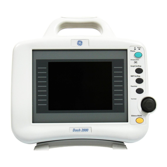
- Page 1 Dash 2000 Patient Monitor Service Manual 2000 412-001 Revision A DASH 2000 Battery Power Charging Status 21-NOV-1998 16:27 DAK.BED 1 150/ Graph Go/Stop 105/ NBP Go/Stop * * * 200/ Function MORE Trim Knob MENUS Silence Alarm...
- Page 2 NOTE: Due to continuing product innovation, specifications in this manual are subject to change without notice. Trademarks Trademarked names appear throughout this document. Rather than list the names and entities that own the trademarks or insert a trademark symbol with each mention of the trademarked name, the publisher states that it is using the names only for editorial purposes and to the benefit of the trademark owner with no intention of improperly using that trademark.
- Page 3 Instructions PN 403409-009 Revision C How to Reach Us . . . Service Calls and To open a service call or obtain product support call the numbers below: Product Support Service calls All products 800-558-7044 (U.S.& Canada) 561-575-5000 (outside U.S.) Product support Monitors 800-558-7044 (U.S.
- Page 4 Other Questions or For additional information contact one of the offices listed below. problems Headquarters GE Marquette Medical Systems, Inc. 8200 West Tower Avenue Milwaukee, Wisconsin 53223 Telephone: 414-355-5000 800-558-5120 (U.S. only) 414-355-3790 Europe GE Marquette Hellige GmbH Postfach 60 02 65 D-79032 Freiburg Germany Telephone: 49-761-4543-0...
-
Page 5: Table Of Contents
CONTENTS Introduction ..........1-1 Manual Information . - Page 6 Contents Respiration ..........2-8 Temperature (TEMP) .
- Page 7 Contents Maintenance ..........3-1 Maintenance Schedule .
- Page 8 Contents Troubleshooting ......... 4-1 Electrostatic Discharge (ESD) .
- Page 9 Contents Error Log Information ........4-17 How Network Errors are Logged ..... . . 4-18 Error Logs .
- Page 10 Contents Load Software From Diskette ....... . . 6-6 About the Procedure ........6-6 Connect the PC to the Monitor .
- Page 11 Contents Upper Level Assembly ........7-1 Safety Information for Disassembly .
- Page 12 Contents viii DASH 2000 Patient Monitor Revision A 2000 412-001...
-
Page 13: Introduction
INTRODUCTION Contents Manual Information ......... 2 Page Layout . -
Page 14: Manual Information
INTRODUCTION: Manual Information Manual Information Scope of the Manual The content of this field service manual is aimed primarily at biomedical equipment technicians and field service personnel. The user of this field service manual is expected to have a solid background in electronics, including strong backgrounds in analog and digital electronics, as well as microcomputer technology familiarity. -
Page 15: Calibration
INTRODUCTION: Manual Information Calibration Chapter five, ÒCalibrationÓ, describes adjustments/jumpers/switches and NBP calibration. ConÞguration Chapter six, ÒConfigurationÓ, describes monitor configurations, installing software, loading software using floppy diskettes and setup or configuration for use. Assembly Drawings Chapter seven, ÒAssembly DrawingsÓ, provides mechanical diagrams, reference diagrams, schematic diagrams and parts lists. -
Page 16: Page Layout
INTRODUCTION: Page Layout Page Layout Section Topic: Each section is Section Title: The top line of divided into topics. This line the page always indicates the indicates what topic within the section of the manual. Section section is covered on this an topics may also appear next to possibly subsequent pages. -
Page 17: Safety Information
INTRODUCTION: Safety Information Safety Information Responsibility of the Marquette Medical Systems is responsible for the effects of safety, reliability, and performance only if: Manufacturer ¥ Assembly operations, extensions, readjustments, modifications, or repairs are carried out by persons authorized by Marquette. ¥... - Page 18 INTRODUCTION: Safety Information Type B equipment; type B equipment is suitable for intentional external and internal application to the patient, excluding direct cardiac application. Equipotentiality Alternating current (AC) Power; = ON; = OFF Fuse Indicates where to press to open the door on the Series 7160 Direct PRESS Digital Writer.
-
Page 19: Notes, Cautions, And Warnings
INTRODUCTION: Safety Information Notes, Cautions, and The safety statements presented in this section apply to the components of the DASH 2000 Patient Monitor. Look for additional safety Warnings information throughout the rest of this manual. The order in which safety statements are presented in no way implies order of importance. -
Page 20: Service Information
INTRODUCTION: Service Information Service Information Service Requirements Follow the service requirements listed below. ¥ Refer equipment servicing to MarquetteÕs authorized service personnel only. ¥ Any unauthorized attempt to repair equipment under warranty voids that warranty. ¥ It is the userÕs responsibility to report the need for service to Marquette Medical Systems or to one of their authorized agents. -
Page 21: Abbreviations
INTRODUCTION: Abbreviations Abbreviations AAMI Association for the DAC digital-to-analog kg kilogram Advancement of converter kHz kilohertz Medical dB decibel kV kilovolt Instrumentation dc direct current ac alternating current DDW Direct Digital Writer LAN local area network ADC analog-to-digital DEFIB defibrillator lb pound converter SYNC... - Page 22 INTRODUCTION: Abbreviations PC printed circuit, SM surface mount V volt, voltage personal computer SPDT single-pole, double- Var variable throw PCB printed circuit board VDE Verband Deutscher Electrotechniker PCMCIA Personal Computer pulse oximetry Memory Card (arterial oxygen Volt voltage International saturation) Association SPST single-pole, single- W watt, West...
-
Page 23: Equipment Overview
EQUIPMENT OVERVIEW Contents Product Description ......... . 2 Front Panel Description . -
Page 24: Product Description
EQUIPMENT OVERVIEW: Product Description Product Description About the Monitor The monitor is a compact, self-contained patient monitor incorporating many advanced features previously found only in complete modular systems. Compact Design Measuring a compact 27 cm (10.5 inches) wide, 22 cm (8.5 inches) tall, and 20 cm (8 inches) deep, and weighing just 5.1 kg (13 pounds), the monitor is thin and unobtrusive enough for locations previously considered impractical. -
Page 25: Front Panel Description
EQUIPMENT OVERVIEW: Front Panel Description Front Panel Description Display Power Indicator Lights Monochrome or color LCD Three indicator lights provide display panel. information about the power Screen size: 5.8 inch diagonal status Resolution: 320 x 240 pixels Front Panel Controls Five pushbutton operator controls provide the following DASH 2000... -
Page 26: Rear Panel Description
EQUIPMENT OVERVIEW: Rear Panel Description Rear Panel Description DEFIB SYNC This connector provides a direct interface between the monitor and a defibrillator for synchronization of the two devices during emergency defibrillation for the synchroni- zed cardioversion. The signals available through this connec- tor are: Outputs •... -
Page 27: Marquette Unity Network
EQUIPMENT OVERVIEW: Marquette Unity Network Marquette Unity Network Monitor Application The Marquette Unity Network (hereafter referred to as the network) provides a method for standardized communication with various Marquette medical systems devices. This versatile monitor can operate both as a fully functional stand-alone device and as a component on the network, depending upon the application. -
Page 28: Performance Specifications
EQUIPMENT OVERVIEW: Performance Specifications Performance SpeciÞcations Performance The Dash 2000 Patient Monitor consists of a self-contained monitor. The Dash 2000 can also operate on battery (DC) power for use as a transport SpeciÞcations monitor. Display Size: 5.8-inch diagonal Type: Monochrome: Hi-Bright Liquid Crystal Display (LCD) Color:... -
Page 29: Ecg
EQUIPMENT OVERVIEW: Performance Specifications Standard leads available: I, II, III, V, aVR, aVL, and aVF Leads analyzed simultaneously: I, II, III, and V (multi-lead mode) Lead fail: Identifies failed lead Alarms: User selectable upper and lower heart rate limits Input specifications: Voltage range: ±0.5 mV to ±5 mV with size 2x or 4x below 1 mV and with QRS width... -
Page 30: Respiration
EQUIPMENT OVERVIEW: Performance Specifications Respiration Measurement technique: Impedance variation detection Range: ±14 Vpk /(330 pF + 20 kOhm) per elec- trode excitation voltage/impedance Respiration rate: 1 Ð 200 breaths per minute Base impedance: 100 to 1000 Ohms at 52.5 kHz excitation frequency Detection sensitivity: 0.4 to 10 Ohms variation... -
Page 31: Pulse Oximetry (Spo2)
EQUIPMENT OVERVIEW: Performance Specifications Alarms: User-selectable upper and lower limits for systolic, diastolic, and mean pressures Pulse Oximetry Parameters monitored: Arterial oxygen saturation (SpO2) and peripheral pulse rate (PPR) (SpO2) SpO2 range: calibrated: 50 Ð 100% total: 0 Ð 100% PPR range: 25 Ð... -
Page 32: Analog Output
EQUIPMENT OVERVIEW: Performance Specifications Analog Output ECG: Gain: 1 V/mV ±10% DC offset: ±100 mV (max) Noise: <5 mVp-p (0-300 Hz) Frequency response: 0.05 Hz to 100 Hz +7/-0 Hz DeÞbrillator Marker out: Time delay: 35 ms (max), R-wave peak to Synchronization Pulse leading edge of pulse. -
Page 33: Physical Specifications
EQUIPMENT OVERVIEW: Performance Specifications Operating conditions: Ambient temperature: 10 to 40 ¡C (50 to 104 ¡F) Relative humidty: 30 Ð 70% Atmospheric pressure: 700 to 1060 hPa Storage conditions: Maximum: 50 ¡C (122 ¡F) at 50% relative humidity, or 70 ¡C (158 ¡F) at 15% relative humidity Minimum: -25 ¡C (-13 ¡F) -
Page 34: Preparation For Use
EQUIPMENT OVERVIEW: Preparation for Use Preparation for Use Power Requirements At least one grounded duplex wall receptacle should be provided for each monitor. The wall receptacle should be hospital grade and installed in a suitable junction box. Power should be provided by a power line dedicated solely to equipment requiring emergency power. -
Page 35: Monitor Ventilation Requirements
EQUIPMENT OVERVIEW: Preparation for Use Monitor Ventilation The monitor is capable of producing as much as 170 BTu per hour of heat load. This is equivalent to approximately 50 watts of energy. Requirements WARNING Failure to properly ventilate the monitor may cause equipment failure or improper monitoring conditions which may endanger the patient being monitored. -
Page 36: Theory Of Operation
EQUIPMENT OVERVIEW: Theory of Operation Theory of Operation General Monitor The theory of operation for the monitor, as covered in this part of the section, is intended to provide an overall block level overview of the Block Theory monitor for service technicians. A general understanding of the theory of operation is required to effectively install, maintain or repair the monitor. -
Page 37: Components
EQUIPMENT OVERVIEW: Theory of Operation Components Power Supply PCB The power supply PCB mounts internally to the monitor rear casting assembly. ItÕs a 40 Watts controllable single output, universal input switching power supply, which has been designed to meet the safety ground leakage current requirements laid down by IEC 60601 and UL 544. -
Page 38: Power Supply Pcb Theory
EQUIPMENT OVERVIEW: Theory of Operation Power Supply PCB The power supply PCB mounts internally to the monitor rear casting assembly. The input voltage is between 85Ð264 V AC / 49Ð64 Hz. The Theory power supply PCB provides a controllable output voltage between 12Ð16 V. -
Page 39: Acquisition Pcb Theory
EQUIPMENT OVERVIEW: Theory of Operation Acquisition PCB The acquisition PCB, or data acquisition system (DAS), located in the monitor, is responsible for the acquisition of all vital-sign patient data. Theory Analog sensor/electrode input signals are amplified and conditioned by hybrid assemblies, then converted to digital data. The digital patient data is transferred across an isolation barrier via high-speed opto-couplers to the processor PCB for analysis and display. -
Page 40: Pcb Functions
EQUIPMENT OVERVIEW: Theory of Operation PCB Functions The acquisition PCB is a microprocessor based data acquisition system with patient isolated power supply included. The DAS can be divided into four main sections: 1. Input sensor/electrode signal conditioning, 2. Analog to digital conversion, 3. -
Page 41: Isolated Power Supply
EQUIPMENT OVERVIEW: Theory of Operation opto-isolators and associated circuitry. The programmable queue allows the QSPI to perform up to sixteen (bytes) serial transfers without CPU intervention. The MC68332 QSPI is designed to be used in a multiprocessor environment where one processor is the master and the other processors are slaves. -
Page 42: Main Processor Pcb Theory
EQUIPMENT OVERVIEW: Theory of Operation Main Processor PCB The main processor PCB provides signal processing, system control, user interface, and communications functions for the monitor, both color LCD Theory and monochrome LCD display versions. It receives and processes digitized patient data from the isolated DAS assembly (acquisition PCB), text and waveform information for the video display, interfaces with the operator via the front panel switches and Trim Knob, and communicates with other products on the network using a built-in Ethernet interface. -
Page 43: Functional Circuits
EQUIPMENT OVERVIEW: Theory of Operation Functional Circuits As a result of the complexity of this board, there are many functional circuits. The functional circuits on the processor PCB include: ¥ Host processing circuit (monitor main processing unit): Ð Motorola MPC821 32-bit integrated microcontroller (25 MHz), Ð... -
Page 44: Pcb Functions
EQUIPMENT OVERVIEW: Theory of Operation PCB Functions The main processor PCB is essentially a self-contained, single-board computer. It includes a Motorola MPC821 microcontroller functioning as the host processor. The MPC821 has an integrated graphics system controller handling the video interface. The system application code is stored in electrically erasable FLASH memory for easy software updates. -
Page 45: Main Memory Configuration
EQUIPMENT OVERVIEW: Theory of Operation Main Memory The main memory consists of 4 megabytes of electrically erasable FLASH memory and 512 Kbyte backed static RAM. All main memory ConÞguration runs at full speed with one wait-states being inserted. The FLASH memory is sector erasable so no separate boot memories are provided (i.e., the main code sectors may be erased without erasing the boot sectors). -
Page 46: Main Connector Pcb Theory
EQUIPMENT OVERVIEW: Theory of Operation Main Connector PCB The main connector PCB is connected to the Main Processor Board and is responsible for the dispersion of signals between the processor PCB and Theory the monitor rear panel connectors. Ethernet, AutoPort communication, and the docking station are the primary functions of the board. - Page 47 MAINTENANCE Contents Maintenance Schedule ........2 Visual Inspection .
-
Page 48: Maintenance Schedule
Maintenance: Maintenance Schedule Maintenance Schedule Manufacturer To make sure the monitor remains in proper operational and functional order, a good maintenance schedule must be adhered to. The recommendation manufacturer's recommendations in this regard are as follows: ¥ Inspection: Operators should perform this prior to admitting each patient to the monitor. -
Page 49: Repair Log
Maintenance: Maintenance Schedule PM Form For the latest PM forms regarding this product, contact GE Marquette Service. Make a copy of the DASH 2000 Patient Monitor PM form and use this copy to help guide you as you go through this chapter of the manual. -
Page 50: Visual Inspection
Maintenance: Visual Inspection Visual Inspection Inspecting the The monitor should be carefully inspected prior to each patient being admitted to the monitoring system. Follow these guidelines when monitor inspecting the equipment: ¥ Carefully inspect the monitor for obvious physical damage to the outer case, display screen and controls. -
Page 51: General Cleaning
Maintenance: General Cleaning General Cleaning A Word About The Dash monitors have a special filter for the display. Specifically, it's a circular-polarized filter with an anti-reflective coating. This type of filter Displays increases the display's contrast while it reduces glare from nearby lights. If you look closely at the display while it's turned off, you might notice milky-white streaks. -
Page 52: Checkout Procedures
Maintenance: Checkout Procedures Checkout Procedures The following pages contain the checkout procedures for the monitor. The purpose of the checkout procedures is to provide service personnel with a method which can be used to verify operational and functional performance of the monitor. Failure to attain any of the listed results indicates a potential malfunction of the monitor. -
Page 53: Ecg Tests
Maintenance: Checkout Procedures NOTE If indicator blinks yellow, then there is a malfunction in the power management system. The unit needs to be repaired. 4. Switch the unit on and disconnect the the power cord. Verify that the BATTERY indicator stays illuminated, AC power indicator and CHARGING STATUS indicator go off. -
Page 54: Checkout Procedures
Maintenance: Checkout Procedures 8. Observe the following while viewing ECG leads II, III, aVR, aVF, and V: ¥ a P appears above the PVC count indicating pacemaker pulse detection is enabled, a star is blinking at each Pacemaker Pulse ¥ if necessary press ÒSilence alarmsÓ. -
Page 55: Respiration Tests
Maintenance: Checkout Procedures Respiration Tests 1. With the ECG patient cable still connected to the ECG/RESP connector of the monitor, set up the patient simulator as follows: ¥ Respiration (RESP) baseline impedance Ð 750 ½, ¥ RESP ÆR Ð 0.5 ½, ¥... -
Page 56: Pulse Oximetry Tests
Maintenance: Checkout Procedures 2. Connect the BP simulator cable from the BLOOD PRESSURE 1 - 120/80 connector of the patient simulator to the BP connector of the monitor. 3. Select ART as pressure site. Verify the ART parameter window, waveform label, corresponding graticules, and waveform appear on the monitor display, along with a BP waveform requiring zero reference. -
Page 57: Noninvasive Blood Pressure Test
Maintenance: Checkout Procedures 6. Verify accuracy of the SPO % values (these are the white NELLCOR values shown on the SpO simulator) on the monitor display using the SpO simulator settings from the following table: Simulator Setting Displayed SPO % Value 95.5% 92 Ð... - Page 58 Maintenance: Checkout Procedures 2. Apply power to the monitor. ¥ Plug the power cord into a working ac power wall receptacle and turn the monitor on. 3. Use the Trim Knob control to scroll to MONITOR SETUP in the monitor main menu and press the Trim Knob control to select it. PATIENT MAIN ALARM...
- Page 59 Maintenance: Checkout Procedures 6. Connect a cuff and manometer to the monitor as shown below. NBP tubing pn 414873-001 6-inch diameter PVC pipe (or 1-pound coffee can): Wrap the NBP cuff around this for tests. Coupling pn 46100-002: Connects manometer tubing to NBP tubing.
- Page 60 Maintenance: Checkout Procedures 8. Rotate the Trim Knob control to highlight CALIBRATE AND TEST and press the Trim Knob control to select it. Next, rotate the Trim Knob control to highlight CALIBRATE NBP and press the Trim Knob control to select it. MONITOR / TIME MAIN...
- Page 61 Maintenance: Checkout Procedures DeÞbrillator 1. Use the figure at the left as a reference for connecting the oscilloscope to the DEFIB SYNC connector, located on the back panel Synchronization of the monitor, for performing these tests. Tests 2. Test the ECG and Marker Out signals from the DEFIB SYNC connector.
-
Page 62: Defibrillator Synchronization Tests
Maintenance: Checkout Procedures DEFIB SYNC connector: Signal Pin: Marker Out (frequency) Ground Pin: Time/Division: 0.2 s Volts/Division: 1 V, when Defi Sync output configured for 5 V DEFIB SYNC connector: Signal Pin: Marker Out (pulse width) Ground Pin: Time/Division: 5 ms Volts/Division: 1 V, when Defi Sync output configured... -
Page 63: Speaker Tests
Maintenance: Checkout Procedures Speaker Tests 1. Set HR limits so, that HR exceeds the limits and alarm tone occurs. 2. Change the alarm volume of the monitor to 100%. 3. Verify the speaker volume of the monitor changes accordingly. 4. Return the volume of the monitor to the level it was previously set to, before you changed it for this test. -
Page 64: Electrical Safety Tests
Maintenance: Electrical Safety Tests Electrical Safety Tests General Electrical safety tests provide a method of determining if potential electrical health hazards to the patient or operator of the device exist. Recommendations To help you establish a systematic maintenance routine, Marquette recommends that you perform all safety tests presented in this chapter ¥... -
Page 65: Wall Receptacle Test
Maintenance: Electrical Safety Tests Wall Receptacle Test Before starting the tests, the wall receptacle from which the monitoring device will get electrical power must be checked. This test checks the condition of the wall receptacle to ensure correct results from leakage tests. - Page 66 Maintenance: Electrical Safety Tests Consult your country/local safety agency if in question. Compliance is checked by the following steps: 1. A current not less than 10A and not exceeding 25 A from a current source with a frequency of 50 or 60 Hz with a no-load voltage not exceeding 6 V is passed for at least 5 s through the PROTECTIVE EARTH TERMINAL or the protective earth pin in the MAINS PLUG and each ACCESSIBLE METAL PART which could become LIVE in...
-
Page 67: Ground (Earth) Wire Leakage Current Tests
Maintenance: Electrical Safety Tests Ground (Earth) Wire Perform this test to measure current leakage through the ground (earth) wire of the equipment during normal operation. Leakage Current 1. Set the leakage tester switches as follows: Tests ¥ Selector knob Ð 1, ¥... - Page 68 Maintenance: Electrical Safety Tests 7. Set the polarity switch on the leakage tester to RVS (reverse). 8. Read the current leakage indicated on DMM. If the reading is greater than the appropriate specification below, the device under test fails and should be repaired and tested again. ¥...
-
Page 69: Enclosure Leakage Current Test
Maintenance: Electrical Safety Tests Enclosure Leakage Perform this test to measure current leakage through exposed conductive surfaces on the device under test during normal operation. Current Test 1. Set the leakage tester switches as follows: ¥ Selector knob Ð 2, ¥... -
Page 70: Test Completion
Maintenance: Electrical Safety Tests 9. Set the leakage tester power switch to OFF and remove the meter lead connected in step 2. Leakage Tester Partial Schematic HIGH NORM Power cord Device under test M.D. (Measuring Device) Probe to exposed conductive chassis Test Completion Disconnect all test equipment from the device. -
Page 71: Patient (Source) Leakage Current Test
Maintenance: Electrical Safety Tests Patient (Source) This procedure only applies to Class I (grounded/earthed) equipment, and measures the leakage current from the ECG/RESP connector of the Leakage Current Test device to ground. 1. Set leakage tester switches as follows: ¥ Selector knob Ð... - Page 72 Maintenance: Electrical Safety Tests 8. Change the GND switch to the CLOSED position. Leakage Tester Partial Schematic HIGH NORM Power cord Device under test M.D. Patient cable or test body (Measuring Device) 9. Read the leakage current indicated on the DMM. If the reading is greater than 10 µA (0.01 volts on the DMM), the device under test fails this test and should be repaired and tested again.
-
Page 73: Patient (Source) Leakage Current Test
Maintenance: Electrical Safety Tests Patient (Source) This procedure only applies to Class I (grounded/earthed) equipment, and measures the leakage current from the SpO connector of the device Leakage Current Test to ground. 1. Set leakage tester switches as follows: ¥ Selector knob Ð... - Page 74 Maintenance: Electrical Safety Tests 8. Change the GND switch to the CLOSED position. Leakage Tester Partial Schematic HIGH NORM Power cord Device under test M.D. Test body (Measuring Device) 9. Read the leakage current indicated on the DMM. If the reading is greater than 10 µA (0.01 volts on the DMM), the device under test fails this test and should be repaired and tested again.
- Page 75 Maintenance: Electrical Safety Tests Patient (Sink) This procedure only applies to Class I (grounded/earthed) equipment, and measures the leakage current from a mains voltage source into the Leakage Current Test ECG/RESP connector. (Mains Voltage on the 1. Set the leakage tester switches as follows: Applied Part) ¥...
- Page 76 Maintenance: Electrical Safety Tests 6. Read the leakage current indicated on the DMM. If the reading is greater than the appropriate specification below, the device under test fails this test and should be repaired and tested again. ¥ 10 µA (0.01 volts on the DMM) at 120 VAC without the patient cable.
- Page 77 Maintenance: Electrical Safety Tests Patient (Sink) This procedure only applies to Class I (grounded/earthed) equipment, and measures the leakage current from a mains voltage source into the Leakage Current Test connector. (Mains Voltage on the 1. Set the leakage tester switches as follows: Applied Part) ¥...
-
Page 78: Test Completion
Maintenance: Electrical Safety Tests 6. Read the leakage current indicated on the DMM. If the reading is greater than the appropriate specification below, the device under test fails this test and should be repaired and tested again. ¥ 10 µA (0.01 volts on the DMM) at 120 VAC without the patient cable. -
Page 79: Hi-Pot (Dielectric Withstand) Test
Maintenance: Electrical Safety Tests Hi-Pot (Dielectric The high potential (Hi-Pot) tests provide a method of checking patient isolation circuits and protect patients connected to the device under test Withstand) Test from potential electrical health hazards. These tests are recommended for direct patient-connected medical devices to check the integrity of the patient isolation circuitry after any isolated component in the device has been repaired. -
Page 80: Ac Hi-Pot Test
Maintenance: Electrical Safety Tests AC Hi-Pot Test Perform the AC hi-pot tests only on the ECG/RESP front panel connector of the device under test. CAUTION Never attempt to perform this test on any of the other front panel connectors of the device under test. Damage to the device under test may occur if this test is performed on any of the other front panel connectors. -
Page 81: Repair Log
Maintenance: Repair Log Repair Log A repair log is included for your convenience to record the repair history of this product. Unit Serial Number: Institution Name: Date Maintenance / Repair Technician Revision A DASH 2000 Patient Monitor 3-35 2000 412-001... - Page 82 Maintenance: Repair Log 3-36 DASH 2000 Patient Monitor Revision A 2000 412-001...
- Page 83 TROUBLESHOOTING Contents Electrostatic Discharge (ESD) ....... . . 2 Special Components ......... 3 Battery Failure .
-
Page 84: Troubleshooting
TROUBLESHOOTING: Electrostatic Discharge (ESD) Electrostatic Discharge (ESD) CMOS Components The monitor makes extensive use of CMOS components because they are more immune to noise and consume less power than standard TTL or NMOS components. However, CMOS components are inherently more susceptible to electrostatic discharge (ESD) damage than other types of semiconductor materials. -
Page 85: Special Components
TROUBLESHOOTING: Special Components Special Components Surface Mounted Surface mounted devices are used to aid in miniaturizing the electrical/ electronic assemblies within the monitor. Devices Surface mounted integrated circuits have legs that are soldered to rectangular pads on the surface of the printed circuit board (PCB), versus pin-through devices having legs that are made to be inserted into solder fillets protruding completely through a PCB. -
Page 86: Battery Failure
TROUBLESHOOTING: Battery Failure Battery Failure Defective Battery/ The BATTERY DEFECTIVE message is displayed in the STATUS MESSAGE line when errors have occurred within the battery Battery System management system or the battery. The reason of the battery system error can be found in the error log-book (MONITOR SETUP Ð> SERVICE MENU Ð>... -
Page 87: Opening The Device And Battery Replacement
TROUBLESHOOTING: Battery Failure Opening the Device and 1. Disassemble the DASH 2000 Assembly as described in "Disassembly Procedure". Battery Replacement 2. Disconnect battery connector and remove the 2 screws from the battery bracket. 3. Remove old battery and insert the new battery. 4. -
Page 88: Power Source Tests
TROUBLESHOOTING: Power Source Tests Power Source Tests AC Line Voltage Test This test verifies that the domestic wall outlet supplying power to the equipment is properly wired For international wiring tests, refer to the internal standards agencies of that particular country. 120 VAC, 50/60 Hz Use a digital voltmeter to check the voltages of the 120-volt AC wall outlet (dedicated circuit recommended). -
Page 89: Power Cord And Plug
TROUBLESHOOTING: Power Source Tests Power Cord and Plug Verify the power cord being used with the monitor is good. The following are a couple of things to check for in this regard: ¥ Failure of the power cord strain relief is very common. Often times users of the equipment pull on the power cord itself, rather than the power cord plug, to unplug the monitor from a wall receptacle. -
Page 90: Data Acquisition Tests
TROUBLESHOOTING: Data Acquisition Tests Data Acquisition Tests ECG Functions 1. Connect the MEI Multifunction Microsimulator, pn MARQ1, and appropriate patient cables, to the ECG connector of the monitor. Turn the monitor and the patient simulator on. 2. Set the monitor to display leads I, II, and III and a second time to I, II and V: ¥... -
Page 91: Ecg Waveforms Display Incorrectly
TROUBLESHOOTING: Data Acquisition Tests 1 mV 1 cm ECG Waveforms Display 1. If the calibration pulses were not correct, test the patient simulator using a working monitor. If the patient simulator is functioning as Incorrectly designed, you may need to replace the acquisition PCB. 2. -
Page 92: Pace Detect Functions Do Not Work Properly
TROUBLESHOOTING: Data Acquisition Tests Pace Detect Functions If the pacemaker detection test results are not correct, as described above: Do Not Work Properly ¥ Verify the patient simulator is functioning correctly by testing it on a working monitor, ¥ The acquisition PCB is suspect. Swap a working acquisition PCB into the monitor and perform these test to verify correct operation. -
Page 93: Generate Static Bp Waveform
TROUBLESHOOTING: Data Acquisition Tests Generate Static BP Set the patient simulator BP output to 200 mmHg, static pressure. Waveform ¥ Verify the BP channel is working correctly if systolic, diastolic, and mean pressure values for ART are displayed between 194 and 206 mmHg. -
Page 94: No Respiration Waveform Or Rate Appear On The Display
TROUBLESHOOTING: Data Acquisition Tests Verify the following: ¥ Respiration rate is displayed and accurate. ¥ Respiration waveform is displayed and noise-free. ¥ Markers appear in the displayed respiration waveform (refer to figure at left). These indicate the points at which the monitor senses inspiration and expiration for determination of the respiration rate. -
Page 95: Noninvasive Blood Pressure Functions
TROUBLESHOOTING: Data Acquisition Tests Noninvasive Blood Perform the noninvasive blood pressure (NBP) Checkout Procedure found in Chapter 3, ÒMaintenanceÓ. This procedure determines whether Pressure Functions or not the NBP functions of the monitor are working as designed or whether the monitor requires NBP calibration. If, after performing the prescribed checkout procedure, it is determined that there are potential problems that NBP calibration does not cure, try the following:... -
Page 96: Service Mode Menu
TROUBLESHOOTING: Service Mode Menu Service Mode Menu The SERVICE MODE menu option items provide the user access to several general and technical built-in software functions of the monitor. Only persons responsible for configuring and maintaining the monitor should access the service mode menu option items. WARNING The Service Mode menu is intended for use only by qualified service technicians. -
Page 97: Access To The Service Mode Menu
TROUBLESHOOTING: Service Mode Menu ADDRESS SET UNIT NAME Ñ For setup or configuration of the monitor care unit name, SET BED NUMBER Ñ For setup or configuration of the monitor bed number or bed name, SET INTERNET ADDRESS Ñ For setup or configuration of the monitor Internet address for the network, REVIEW ERRORS Ñ... -
Page 98: About Service Mode Menu Option Items
TROUBLESHOOTING: Service Mode Menu ¥ Repeat these steps until all password numbers are correctly displayed. ¥ Once you have entered the correct password numbers, rotate the Trim Knob control to highlight SERVICE MODE in the enter password window. ¥ Press the Trim Knob control one more time to enter the password and access the service menus of the monitor. -
Page 99: Accessing The Review Errors Menu Option Item
TROUBLESHOOTING: Service Mode Menu Accessing the Review To access the error log and learn more about the REVIEW ERRORS menu option item, follow these steps: Errors Menu Option Item 1. Rotate and press the Trim Knob control to scroll to and select REVIEW ERRORS from the service mode menu option items. -
Page 100: How Network Errors Are Logged
TROUBLESHOOTING: Service Mode Menu A sample of the monitor error log pop-up window appears as follows: When using the error log to troubleshoot a problem with the monitor, the following parameters from the pop-up window that are of greatest interest are: Process Name: Ñ... -
Page 101: Severity Of The Error
TROUBLESHOOTING: Service Mode Menu Severity of the Error Severity is a measure of how the event/error affected the system. There are three levels of severity. The following is a list of these levels accompanied by a brief description of each: Continue: Ñ... -
Page 102: Service Tips
TROUBLESHOOTING: Service Tips Service Tips Fault/Symptom This information is provided for the benefit of service technicians responsible for the maintenance and repair of the monitor. The Analysis symptoms covered in this part of the Troubleshooting section represent only a select number of faults that you may encounter and by no means are intended to cover every possible failure that may occur. -
Page 103: Processor Pcb Symptoms
TROUBLESHOOTING: Service Tips Processor PCB Symptoms with network communications, asynchronous communications, NBP control, analog output, audio/sound generation, Symptoms and remote video signals/communications as well as other display-related problems all may be associated with processor PCB failure. All of these are functions controlled by microcontroller or graphics processing circuitry located on the processor PCB. -
Page 104: Power Supply Fuses
TROUBLESHOOTING: Service Tips Power Supply Fuses The power supply has two 2-Ah fuses (slow-blow) on the primary side. If these fuses fail, the power supply must be replaced, not the fuses. For the secondary side, there is a 4-Ah fuse (slow-blow) on the PCB Mainboard. If this fuse blows, the entire PCB Mainboard has to be replaced, because the fuse is soldered onto the board. -
Page 105: Calibration
CALIBRATION Contents Adjustments and Switches ........2 Main Processor PCB . -
Page 106: Adjustments And Switches
CALIBRATION: Adjustments and Switches Adjustments and Switches Hardware Calibration The following table summarizes the hardware adjustments and switches on the monitor. The hardware adjustments are only necessary if a circuit board is repaired or replaced. Reference Designation Description Main Processor PCB: 2-station DIP switch, LCD Type and Watchdog Main Connector PCB: None... -
Page 107: Main Processor Pcb
CALIBRATION: Main Processor PCB Main Processor PCB The main processor PCB has a 2-station DIP switch. This switch is used to configure the LCD display type color or monochrome and the watchdog ON or OFF. Switch S1 Settings As you can see in the picture below the 2-station DIP switch S1 can be found on the PCB Mainboard between the LCD connector HOS for the monochrome LCD display and the KYO connector for the color display. -
Page 108: Noninvasive Blood Pressure
CALIBRATION: Noninvasive Blood Pressure Noninvasive Blood Pressure The overall accuracy of noninvasive blood pressure (NBP) readings by the monitor depend on the following: ¥ the zero pressure reading, and ¥ the voltage span of the NBP sensor in the monitor. This procedure provides a method of verifying these items are accurate and also checks the NBP pneumatic circuit plumbing for leaks. -
Page 109: Calibration Procedure
CALIBRATION: Noninvasive Blood Pressure Calibration 1. Remove all cables except for the power cord from the monitor. Procedure 2. Apply power to the monitor. ¥ Plug the power cord into a working ac power wall receptacle and turn the monitor on. 3. -
Page 110: Service Menus
CALIBRATION: Noninvasive Blood Pressure Service Menus The service menus should appear on the monitor display. These next steps guide you through the service menus associated with checking NBP calibration. If desired test results are not obtained, NBP calibration is necessary. 1. - Page 111 CALIBRATION: Noninvasive Blood Pressure 4. Connect a cuff and manometer to the monitor as shown below. NBP tubing pn 414873-001 6-inch diameter PVC pipe (or 1-pound coffee can): Wrap the NBP cuff around this for tests. Coupling pn 46100-002: Connects manometer tubing to NBP tubing.
-
Page 112: Start The Gain Calibration Test
CALIBRATION: Noninvasive Blood Pressure Start the Gain Calibration 1. Rotate the Trim Knob control to highlight CAL GAIN OFF, and then press the Trim Knob control to select it. Test CHECK MAIN ZERO: CAL: MENU PREV. GAIN: MENU 2. Rotate the Trim Knob control to highlight CAL GAIN OFF, and then press the Trim Knob control to select it. - Page 113 CALIBRATION: Noninvasive Blood Pressure 5. Rotate the Trim Knob control to highlight ENTER CAL PRESSURE and press the Trim Knob control to select it. MAIN GAIN: MENU HOLDING ENTER PREV. MENU PRESSURE 6. An ENTER CAL PRESSURE pop-up window will appear. Use the Trim Knob control to select a pressure value that is 1 mmHg lower than the current manometer reading.
- Page 114 CALIBRATION: Noninvasive Blood Pressure as CUFF in the NBP parameter box) on the monitor and manometer are equal (± 1 mmHg) for at least one full minute. 21-JUN-1999 16:27 ICU-BED 5 MARTIN 150/ 200/ CUFF CHECK MAIN ZERO: CAL: MENU IN PROG PREV.
- Page 115 CONFIGURATION Contents Monitor Configurations ........2 Loading Software .
-
Page 116: Monitor Configurations
CONFIGURATION: Monitor Configurations Monitor ConÞgurations Setup For Use The last part of this section is devoted to setup or configuration of the monitor. Also refer to the Marquette Unity Network UserÕs Manual, pn. 403799-023, for information relative to setup or configuration of other patient monitoring system components. -
Page 117: Loading Software
CONFIGURATION: Loading Software Loading Software Intended Use This part of the section is for the purpose of loading manufacturer software into the monitor initially, reloading software when the possibility of corrupted software exists, or updating software in the event of a release of a new software revision. Software Loading/ The process of loading or updating software in the monitor is described in this part of the section. -
Page 118: Monitor Software Files
CONFIGURATION: Loading Software To stop test pattern, follow step (1) to (5), then select STOP. If there is a previous revision of software residing in the monitor memory, update the monitor as necessary. Keep the monitor at current levels of manufacturer software to maintain the proper network communication and to provide the user with all of the latest operational features that the manufacturer offers. -
Page 119: Maintain Patient Monitoring
CONFIGURATION: Loading Software Maintain Patient The monitor is not capable of downloading code while connected to a patient. Inform medical staff responsible for patients connected to the Monitoring monitor that the equipment is going to be updated so they may take appropriate actions. -
Page 120: Load Software From Diskette
CONFIGURATION: Load Software From Diskette Load Software From Diskette About the Procedure This procedure describes how to update software in the monitor from a PC or PC laptop floppy disk drive using update diskettes provided in the manufacturers software update kits. This update procedure requires the following: 1. -
Page 121: Update Program Start-Up
CONFIGURATION: Load Software From Diskette Update Program Start the update download program from an update diskette to begin loading software into the monitor by following these steps: Start-up 1. Apply power to the PC and wait for the C:\> prompt to appear on the PC display. -
Page 122: Files On Diskette 4
CONFIGURATION: Load Software From Diskette Files on Diskette 4 Below is the list of update files typically found on Diskette 4. Diskette 4 Files File Name Description 45668900.xxx MAIN BOOT 41510500.xxx DAS BOOT Files on Diskette 5 Below is the list of update files typically found on Diskette 5. Diskette 5 Files File Name Description... -
Page 123: Setup Monitor To Accept Download Files
CONFIGURATION: Load Software From Diskette Setup Monitor to The PC and the monitor are serially linked, communication-wise. The following steps describe how to download a specific file into monitor Accept Download memory. In order to proceed, the monitor must be enabled to receive Files update files. -
Page 124: Download Files To The Monitor
CONFIGURATION: Load Software From Diskette Download Files to At this point, the monitor is ready to accept download files and the PC is setup to provide the files for download. Follow the next steps once the PC the Monitor and monitor are setup for download. 1. -
Page 125: Errors During Download Process
CONFIGURATION: Load Software From Diskette Errors During Download For most errors, simply press RETURN on the PC or repeat the download procedure. If the byte numbers stop advancing for more than Process two minutes, refer to ÒProblems While Loading SoftwareÓ found in the ÒIntroductionÓ... -
Page 126: Verify Software Update
CONFIGURATION: Load Software From Diskette Verify Software Update Verify the software downloaded successfully. Execute the following menu option selection sequence, beginning at the monitor main menu: MONITOR SETUP SOFTWARE SUMMARY Press the GRAPH GO/STOP key Compare the displayed monitor software revisions with those previously printed or written down. -
Page 127: Load Software Over The Network
CONFIGURATION: Load Software Over The Network Load Software Over The Network About the Procedure This section of the procedure provides instructions to load the contents of update diskettes 1, 2, and 3 to a Centralscope central station or Clinical Information Center (CIC) system hard disk drive, initiate the central station as a file server from the monitor, and download software to the monitor over the patient monitoring network. -
Page 128: Centralscope Central Station
CONFIGURATION: Load Software Over The Network Centralscope 1. At the Centralscope central station, execute the following menu sequence, starting from the MAIN menu: Central Station CENTRAL SETUP, SERVICE, PASSWORD (MEI CS 123), LOAD SOFTWARE (Wait 10 seconds), and FLOPPY. 2. Observe status messages in the upper left corner of the central station display. -
Page 129: Download Files To The Monitor
CONFIGURATION: Load Software Over The Network 3. Follow the instructions on the screen to exchange diskettes in the hard drive as each one is loaded on the Clinical Information Center hard drive. 4. When loading of diskette 3 is complete, the Clinical Information Center displays the message: INSTALL COMPLETE. - Page 130 CONFIGURATION: Load Software Over The Network 5. From the SCRIPT NAME SELECTION menu list, use the Trim Knob to scroll to and select the number corresponding to the file (script) requiring update. Following is a list of files that appear in the SCRIPT NAME SELECTION menu (listed in sequential order for each script to be loaded): *MAIN.SCR,...
-
Page 131: Activate Software
CONFIGURATION: Load Software Over The Network Activate Software You may download all the monitors in the care unit, then activate the upgraded software. After all of the files have been successfully loaded, press the monitor power switch to OFF then ON to operate the monitor with the newly loaded software. - Page 132 CONFIGURATION: Load Software Over The Network 4. Load or update software for each monitor as required. Update software to current revisions in all monitors for best monitor performance and operation. 6-18 DASH 2000 Patient Monitor Revision A 2000 412-001...
-
Page 133: Setup For Use
CONFIGURATION: Setup For Use Setup For Use About Setup This part of the section contains the procedure for initial setup or configuration of the monitor. The procedure addresses use in both types of patient monitoring system configurations: ¥ Stand-alone patient monitor: The monitor is not interconnected to other patient monitoring system devices, and ¥... -
Page 134: Procedure Summary
CONFIGURATION: Setup For Use Procedure Summary Below is a summary of the procedure to setup the monitor for normal operation: 1. Determine the current monitor software revision level. 2. Setup the monitor care UNIT NAME. 3. Setup the monitor BED NUMBER. 4. -
Page 135: The Main Monitor Menu
CONFIGURATION: Setup For Use The Main Monitor Menu The topmost level (master directory) of the monitor operating system software is the main menu; the menu that normally remains displayed when there is no operator intervention on the monitor. The main menu includes a normal patient monitoring display plus five menu option items. -
Page 136: Software Summary Pop-Up Window
CONFIGURATION: Setup For Use Software Summary The software revisions of each processing circuit within the monitor are displayed in a pop-up window similar to the one shown below. Pop-up Window 21-NOV-1998 16:27 DAK.BED 1 SOFTWARE SUMMARY SOFTWARE REVISIONS MAIN 414957-006 INT5 02OCT1998 MAIN BOOT 414959-005 3B 18FEB97 DAS BOOT... - Page 137 CONFIGURATION: Setup For Use 5. A service menu password window appears on the monitor display. 21-NOV-1998 16:27 DAK.BED 1 CAUTION !! YOU ARE ABOUT TO ENTER THE SERVICE MODE OF OPERATION. IF YOU PROCEED, YOU MAY LOSE YOUR MONITOR CONFIGURATION. SOME OPERATIONS WILL CAUSE A COLD START OF THE MONITOR.
-
Page 138: Unit Name
CONFIGURATION: Setup For Use Unit Name From the service mode menu option items which appear on the monitor display, follow the next steps of the procedure to setup or configure the UNIT NAME of the monitor. About the Monitor Unit The monitor UNIT NAME provides a means of differentiating groups of devices on the network. - Page 139 CONFIGURATION: Setup For Use 3. The SET UNIT NAME pop-up window appears on the monitor display as shown below. MAIN UNIT MENU NAME PREV. MENU The SET UNIT NAME pop-up window displays either the current care UNIT NAME or is completely blank. The software supports up to seven alphanumeric characters to be used in the UNIT NAME field.
-
Page 140: Bed Number
CONFIGURATION: Setup For Use Bed Number From the service mode menu option items which appear on the monitor display, follow the next steps of the procedure to setup or configure the BED NUMBER of the monitor. About the Monitor Bed The monitor BED NUMBER is manually programmed into monitor. - Page 141 CONFIGURATION: Setup For Use 3. The SET BED NUMBER pop-up window appears on the monitor display as shown below. MAIN UNIT MENU NAME NUMBER PREV. MENU The SET BED NUMBER pop-up window displays either the current BED NUMBER or is completely blank. The software supports up to five alphanumeric characters to be used in the BED NUMBER field.
-
Page 142: Graph Locations
CONFIGURATION: Setup For Use Graph Locations One area of monitor setup or configuration that most often is overlooked, is the setup or configuration of each GRAPH LOCATION for the monitor. Three types of graphs can be generated by the monitor: manual, alarm and print windows. - Page 143 CONFIGURATION: Setup For Use 2. Use the Trim Knob control on the front panel of the monitor to select GRAPH SETUP from the monitor setup menu option items. MAIN MONITOR DISPLAY GRAPH MENU DEFAULTS SETUP SETUP PREV. PARAM. SOFTWARE SERVICE MENU ON / OFF SUMMARY...
-
Page 144: Select A Writer
CONFIGURATION: Setup For Use Select a Writer The graph location pop-up list appears in the left portion of the monitor display. 21-NOV-1998 16:27 DAK.BED 1 MANUAL GRAPH LOCATION: > RETURN CS 2 WRITER BED3 WRITER CS 1 WRITER BED1 WRITER BED5 WRITER MANUAL... -
Page 145: Time And Date Setup
CONFIGURATION: Setup For Use Time and Date Setup The TIME AND DATE function of the monitor provides a means for the real time clock circuit to be setup correctly or changed by the user. The TIME AND DATE setup or configuration of the monitor is used mainly for the purpose of documentation of patient events and history files stored in the monitor each time a patient is admitted. - Page 146 CONFIGURATION: Setup For Use ¥ For a stand-alone monitor (not connected to the network), select the menu option from the DISPLAY SETUP menu. color version MAIN WAVEFORM CONTRAST COLOR: MENU ON / OFF 25 % CLINICAL TIME PREV. MENU DATE monochrome MAIN WAVEFORM...
-
Page 147: Upper Level Assembly
UPPER LEVEL ASSEMBLY Contents Safety Information for Disassembly ......2 Disassembly Procedure ........3 Spare Parts List . -
Page 148: Safety Information For Disassembly
UPPER LEVEL ASSEMBLY: Safety Information for Disassembly Safety Information for Disassembly Please observe the following safety information when disassembling the monitor. ESD Protection All PCBs contain semiconductor which must be protected from electrostatic discharge. When working on open montiors and when handling PCBs, it is important to observe ESD safety precautions. -
Page 149: Disassembly Procedure
UPPER LEVEL ASSEMBLY: Disassembly Procedure Disassembly Procedure Preparations before Before any service interventions, turn off the device and disconnect the device from power line. Opening the monitor Opening Unit To open the unit, do the following. 1. Lay the monitor with the front panel face down on a clean, level surface (ESD pad) which is placed on a soft material to avoid scratches on the front panel. - Page 150 UPPER LEVEL ASSEMBLY: Disassembly Procedure DASH 2000 1. Open the unit as described in Opening Unit. Assembly 2. Remove the 2-pole converter plug and the flat cable connector for the display from the PCB Mainboard. 3. Tilt the display frame with the DAS board towards the front. 4.
- Page 151 UPPER LEVEL ASSEMBLY: Disassembly Procedure 5. Undo the 3 screws which hold the PCB Mainconnector and remove it. 6. Disconnect DAS flat cable from PCB Mainboard. 7. Remove ground wire from PCB Mainboard. 8. Undo the 2 hexagonal spacers and the 3 screws which hold the PCB Mainboard.
-
Page 152: Spare Parts List
UPPER LEVEL ASSEMBLY: Spare Parts List Spare Parts List Printed circuit boards and assemblies* Part Part Description Part Number Pcb. Main Board Pcb. Mainboard with latest software in english language 303 44808 Pcb.Main Board Exchange Pcb. Mainboard with latest software in english 389 00434 language Pcb. - Page 153 UPPER LEVEL ASSEMBLY: Spare Parts List Mechanical Parts Part Part Description Part Number Front Bezel Front Bezel incl. Filter. Labels (language dependent) have to be 2000347-001 ordered seperately. Chassis Housing rear (metal) not for field replacement 419030-004 Bracket Writer MTG Bracket as housing for the recorder.
- Page 154 UPPER LEVEL ASSEMBLY: Spare Parts List Labels All the labels for one specific language for Dash 2000 are on one label set Part Part Description Part Number Label Kit English Label Kit with labels for Dash 2000 in English language 422691-001 Label Kit German Label Kit with labels for Dash 2000 in German language...
- Page 155 UPPER LEVEL ASSEMBLY: Spare Parts List Documents Part Part Description Part Number Service Manual Service Manual Dash 2000 V1 2000412-001 User Manual User Manual V1 US/English 22749904 User Manual User Manual V2 German 22749901 User Manual User Manual V2 French 22749902 User Manual User Manual V2 Spanish...
- Page 156 UPPER LEVEL ASSEMBLY: Spare Parts List 7-10 DASH 2000 Patient Monitor Revision A 2000 412-001...
- Page 157 ASSEMBLY DRAWINGS Contents Revision A DASH 2000 Patient Monitor 2000 412-001...
- Page 158 ASSEMBLY DRAWINGS: Introduction Introduction Included in this section is a complete set of mechanical diagrams, reference diagrams, schematic diagrams and parts lists. Mechanical diagrams Ñ These diagrams show the mechanical assembly of the Dash 2000 monitor. Reference diagrams Ñ These diagrams provide a reference and view of the used components in the schematic.
- Page 160 Sheet: Marquette Hellige GmbH 388 032 75 P D-79007 Freiburg REVISIONS Not equipped in Version : F67256 Revision-No Index Date / Name LPL Main Board 13.11.98/PHG Date / Name 02.03.99/PHG DRAWN 13.11.98/PHG 13.11.98/PHG APPROVED PCB Main Board ISSUED PH.GEIGER [1997, 10, 22, 4] $USER_CAE_B/dash2000/main_board/design...
- Page 161 Sheet: Marquette Hellige GmbH 388 032 75 P D-79007 Freiburg REVISIONS Not equipped in Version : F67256 Revision-No Index Date / Name LPL Main Board 13.11.98 / WHL Date / Name 02.03.99 / WHL DRAWN 13.11.98/PHG APPROVED 13.11.98/PHG PCB Main Board ISSUED PH.GEIGER [1997, 12, 17, 4]...
- Page 162 Sheet: Marquette Hellige GmbH 388 032 75 P D-79007 Freiburg REVISIONS Not equipped in Version : F67256 Revision-No Index Date / Name LPL Main Board 13.11.98/PHG Date / Name 02.03.99/PHG DRAWN 13.11.98/PHG ECO-062190 07.05.99/PHG APPROVED 13.11.98/PHG PCB Main Board ISSUED PH.GEIGER [1997, 12, 17, 4] $USER_CAE_B/dash2000/main_board/design/modules...
- Page 163 Sheet: Marquette Hellige GmbH 388 032 75 P D-79007 Freiburg REVISIONS Not equipped in Version : F67256 Revision-No Index Date / Name LPL Main Board 13.11.98/PHG Date / Name 02.03.99/PHG DRAWN 13.11.98/PHG APPROVED 13.11.98/PHG PCB Main Board ISSUED PH.GEIGER [1997, 12, 10, 4] $USER_CAE_B/dash2000/main_board/design/memory...
- Page 164 Marquette Hellige GmbH Sheet: 388 032 75 P D-79007 Freiburg REVISIONS Not equipped in Version : F67256 Revision-No Index Date / Name LPL Main Board 38803275 3.11.98/PHG Date / Name 02.03.99/PHG DRAWN 13.11.98/PHG ECO-062190 07.05.99/PHG 13.11.98/PHG APPROVED PCB main board ISSUED PH.GEIGER [1997, 12, 10, 4]...
- Page 165 Sheet: Marquette Hellige GmbH 388 032 75 P D-79007 Freiburg REVISIONS Not equipped in Version : F67256 Revision-No Index Date / Name LPL Main Board 13.11.98/PHG Date / Name 02.03.99/PHG DRAWN 13.11.98/PHG 13.11.98/PHG APPROVED PCB Main Board ISSUED PH.GEIGER [1998, 3, 6, 6] $USER_CAE_B/dash2000/main_board/design/cpu...
- Page 166 Sheet: Marquette Hellige GmbH 388 032 75 P D-79007 Freiburg REVISIONS Not equipped in Version : F67256 Revision-No Index Date / Name LPL Main Board 13.11.98/PHG Date / Name 02.03.99/PHG DRAWN 13.11.98/PHG APPROVED 13.11.98/PHG PCB Main Board ISSUED PH.GEIGER [1997, 12, 11, 5] $USER_CAE_B/dash2000/main_board/design/system...
- Page 167 Sheet: Marquette Hellige GmbH 388 032 75 P D-79007 Freiburg REVISIONS Not equipped in Version : F 67 256 Revision-No Index Date / Name LPL MAIN BOARD 38803275 11.11.98 / WHL Date / Name 02.03.99 / WHL DRAWN 13.11.98/ WHL 061670 08.07.99 / HAW APPROVED...
- Page 168 Sheet: Marquette Hellige GmbH 388 032 75 P D-79007 Freiburg REVISIONS Not equipped in Version : F67256 Revision-No Index Date / Name LPL Main Board 22.10.98 / WHL Date / Name 02.03.99/PHG DRAWN 13.11.98/WHL 13.11.98/PHG APPROVED PCB Main Board ISSUED PH.GEIGER [1997, 12, 5, 6] $USER_CAE_B/dash2000/main_board/design/power_supply...
- Page 169 Sheet: Marquette Hellige GmbH 388 032 75 P D-79007 Freiburg REVISIONS Not equipped in Version : F67256 Revision-No Index Date / Name LPL Main Board 13.11.98/PHG Date / Name 02.03.99/PHG DRAWN 13.11.98/PHG 13.11.98/PHG APPROVED PCB Main Board ISSUED PH.GEIGER [1997, 12, 18, 5] $USER_CAE_B/dash2000/main_board/design/lcd...
- Page 170 Sheet: Marquette Hellige GmbH 388 032 75 P D-79007 Freiburg REVISIONS Not equipped in Version : F67256 Revision-No Index Date / Name LPL Main Board 38803275 13.11.98/PHG Date / Name 02.03.99/PHG DRAWN 13.11.98/PHG ECO-062190 07.05.99/PHG 13.11.98/PHG APPROVED PCB Main Board 061670 08.07.99/HAW ISSUED...
- Page 171 Sheet: Marquette Hellige GmbH 388 032 75 P D-79007 Freiburg REVISIONS Not equipped in Version : F67256 Revision-No Index Date / Name LPL Main Board 13.11.98/PHG Date / Name 02.03.98/PHG DRAWN 13.11.98/PHG 13.11.98/PHG APPROVED PCB Main Board ISSUED PH.GEIGER [1998, 1, 23, 6] $USER_CAE_B/dash2000/main_board/design/connect...
- Page 172 Sheet: Marquette Hellige GmbH 388 032 75 P D-79007 Freiburg REVISIONS Not equipped in Version : F67256 Revision-No Index Date / Name LPL Main Board 13.11.98/PHG Date / Name 02/03.99/PHG DRAWN 13.11.98/PHG ECO-062190 07.05.99/PHG 13.11.98/PHG APPROVED PCB Main Board ISSUED PH.GEIGER [1997, 12, 17, 4] $USER_CAE_B/dash2000/main_board/design/io_1...
- Page 174 Marquette Hellige GmbH Sheet: 388 032 76 P D-79007 Freiburg REVISIONS Not equipped in Version : F67257 Revision-No Index Date / Name LPL MAIN CONNECTOR 7.12..98/PHG Date / Name 17.03.99/PHG DRAWN 03.12.97/JOK APPROVED 22.04.98/PHG PCB MAIN CONNECTOR P. GEIGER ISSUED [1997, 11, 28, 6] $USER_CAD_A/f67257/design...
- Page 175 Sheet: Marquette Hellige GmbH 388 032 76 P D-79007 Freiburg REVISIONS Not equipped in Version : F67257 Revision-No Index Date / Name LPL MAIN CONNECTOR 30.11.98/PHG Date / Name 17.03.99/PHG DRAWN 03.12.97/JOK 30.04.98/PHG APPROVED PCB MAIN CONNECTOR ISSUED Ph. GEIGER [1997, 11, 28, 6] $USER_CAD_A/f67257/design...
- Page 176 Sheet: Marquette Hellige GmbH 388 032 76 P D-79007 Freiburg REVISIONS Not equipped in Version : F67257 Revision-No Index Date / Name LPL MAIN CONNECTOR 7.12..98/PHG Date / Name 17.03.99/PHG DRAWN 22.04.98/PHG ECO-062191 07.05.99/PHG 4.5.98/PHG APPROVED PCB MAIN CONNECTOR ISSUED Ph.GEIGER [1998, 4, 22, 4] $USER_CAD_A/f67257/design...
- Page 177 Marquette Hellige GmbH Sheet: 388 032 76 P D-79007 Freiburg REVISIONS Not equipped in Version : F67257 Revision-No Index Date / Name LPL MAIN CONNECTOR 7.12..98/PHG Date / Name 17.03.99/PHG DRAWN 03.12.97/JOK APPROVED 30.4.98/PHG PCB MAIN CONNECTOR Ph.GEIGER ISSUED [1998, 4, 24, 6] $USER_CAD_A/f67257/design...
- Page 179 Sheet: Marquette Hellige GmbH 388 032 77 P D-79007 Freiburg REVISIONS Not equipped in Version : F 672 58 Revision-No Index Date / Name LPL DASH 2000 DAS INPUT 18.03.99 / WHL Date / Name 14.07.98 / WHL DRAWN 29.07.98 / WHL APPROVED PCB DASH 2000 DAS INPUT W.LOEHNING...
- Page 183 Marquette Hellige GmbH Sheet: 388 032 78 P D-79007 Freiburg REVISIONS Not equipped in Version : F67259 Revision-No Index Date / Name LPL NIBP 10.02.99/PHG Date / Name DRAWN 26.11.97/JOK APPROVED 27.11.97/PHG PCB NIBP P. GEIGER ISSUED [1997, 11, 24, 2] $USER_CAD_A/f67259/design...
- Page 185 Sheet: Marquette Hellige GmbH 388 032 82 P D-79007 Freiburg REVISIONS Not equipped in Version : F 672 63 Revision-No Index Date / Name LPL DASH 2000 DAS 12.03.99 / WHL Date / Name DRAWN 28.07.98 / WHL APPROVED 28.07.98/ WHL PCB DASH 2000 DAS ISSUED W.LOEHNING...
- Page 186 Sheet: Marquette Hellige GmbH 388 032 82 P D-79007 Freiburg REVISIONS Not equipped in Version : F 672 63 Revision-No Index Date / Name LPL DASH 2000 DAS 12.03.99 / WHL Date / Name ECO 062 187 05.05.99 / WHL DRAWN 28.07.98 / WHL ECO 062 188...
- Page 187 Sheet: Marquette Hellige GmbH 388 032 82 P D-79007 Freiburg REVISIONS Not equipped in Version : F 672 63 Revision-No Index Date / Name LPL DASH 2000 DAS 12.03.99 / GHH Date / Name ECO 062 187 05.05.99 / WHL DRAWN 28.07.98 / WHL ECO 062 188...
- Page 188 Sheet: Marquette Hellige GmbH 388 032 82 P D-79007 Freiburg REVISIONS Not equipped in Version : F 672 63 Revision-No Index Date / Name LPL DASH 2000 DAS 12.03.99 / GHH Date / Name DRAWN 28.07.98 / WHL APPROVED 28.07.98 / GHH PCB DASH 2000 DAS ISSUED W.LOEHNING...
- Page 189 Sheet: Marquette Hellige GmbH 388 032 82 P D-79007 Freiburg REVISIONS Not equipped in Version : F 672 63 Revision-No Index Date / Name LPL DASH 2000 DAS 12.03.99 / GHH Date / Name ECO-062188 08.06.99 / GHH DRAWN 28.07.98 / WHL APPROVED 28.07.98 / GHH PCB DASH 2000 DAS...
- Page 190 Sheet: Marquette Hellige GmbH 388 032 82 P D-79007 Freiburg REVISIONS Not equipped in Version : F 672 63 Revision-No Index Date / Name LPL DASH 2000 DAS 12.03.99 / WHL Date / Name ECO 062 187 05.05.99 / WHL DRAWN 28.07.98 / WHL ECO 062 188...
- Page 191 Sheet: Marquette Hellige GmbH 388 032 82 P D-79007 Freiburg REVISIONS Not equipped in Version : F 672 63 Revision-No Index Date / Name LPL DASH 2000 DAS 12.03.99 / WHL Date / Name DRAWN 28.07.98 / WHL 28.07.98 / WHL APPROVED PCB DASH 2000 DAS ISSUED...
- Page 192 Sheet: Marquette Hellige GmbH 388 032 82 P D-79007 Freiburg REVISIONS Not equipped in Version : F 672 63 Revision-No Index Date / Name LPL DASH 2000 DAS 388 032 82 12.03.99 / WHL Date / Name DRAWN 28.07.98 / WHL 28.07.98 / WHL APPROVED PCB DASH 2000 DAS...
- Page 193 Sheet: Marquette Hellige GmbH 388 032 82 P D-79007 Freiburg REVISIONS Not equipped in Version : F 672 63 Revision-No Index Date / Name LPL DASH 2000 DAS 388 032 82 12.03.99 / WHL Date / Name ECO 062 188 07.06.99 / WHL DRAWN 28.07.98 / WHL...
- Page 194 Sheet: Marquette Hellige GmbH 388 032 82 P D-79007 Freiburg REVISIONS Not equipped in Version : F 672 63 Revision-No Index Date / Name LPL DASH 2000 DAS 388 032 82 12.03.99 / WHL Date / Name DRAWN 28.07.98 / WHL 28.07.98 / WHL APPROVED PCB DASH 2000 DAS...
- Page 195 Sheet: Marquette Hellige GmbH 388 032 82 P D-79007 Freiburg REVISIONS Not equipped in Version : F 672 63 Revision-No Index Date / Name LPL DASH 2000 DAS 388 032 82 ---- 12.03.99 / WHL Date / Name DRAWN 28.07.98 / WHL 28.07.98 / WHL APPROVED PCB DASH 2000 DAS...
- Page 199 Sheet: Marquette Hellige GmbH 388 033 00 P D-79007 Freiburg REVISIONS Not equipped in Version : F67277 Revision-No Index Date / Name LPL VERBINDUNG RECORDER 01.04.99/HAW Date / Name ECO-062234 10.05.99/PHG 08.12.98/PHG DRAWN 09.12.98/MSG APPROVED PCB CONNECTION RECORDER GEIGER ISSUED [1998, 12, 10, 5] $USER_CAD_A/f67277/f67277_design...
- Page 202 Europe Region Asia Region World Headquarters GE Marquette Medical Systems Marquette Hellige GmbH 26/F, Catic Plaza A GE Medical Systems Company 8 Causeway Road 8200 West Tower Avenue Milwaukee, WI 53223 • USA Postfach 60 02 65 Causeway Bay D-79032 Freiburg • Germany Hong Kong Tel.
Need help?
Do you have a question about the marquette Dash 2000 and is the answer not in the manual?
Questions and answers