
Subscribe to Our Youtube Channel
Related Manuals for GE Medical Systems Corometrics 340


Summary of Contents for GE Medical Systems Corometrics 340
- Page 1 Corometrics Model 340 SERVICE MANUAL MANUAL P/N 2006920-001 REV. A 340 Telemetry Receiver TOCO...
- Page 3 Corometrics Model 340 SERVICE MANUAL MANUAL P/N 2006920-001 REV. A 340 Telemetry Receiver TOCO...
- Page 4 Corometrics and Marquette are registered trademarks of GE Medical Systems Information Technologies. GE is a registered trademark of General Electric Company. All other product and brand names are trademarks or registered trademarks of their respective companies.
- Page 5 Contents Figures ......... . v Tables .
- Page 6 Introduction ........2-1 Product Summary ........... 2-2 Product Features .
- Page 7 Calibration ........5-1 FCC Service Information ..........5-2 Test Equipment .
- Page 8 For your notes Model 340 Telemetry System Revision A 2006920-001...
- Page 9 Figures Figure 1-1. Model 340 or Model 340 Plus REF Number ........xi Figure 1-2.
- Page 10 For your notes...
-
Page 11: Troubleshooting
Tables Table 1-1. Definitions of Terminology ..........1-3 Table 1-2. - Page 12 For your notes...
- Page 13 Preface Overview of Telemetry Systems This chapter provides an overview of the 340 Series of telemetry systems: About Your System ........Identifying Your System .
- Page 14 Overview of Telemetry Systems: About Your System About Your System Due to continuing product innovations, there are three versions of the Model 340 Telemetry System in hospitals today. All three versions operate identically from a user’s perspective. Unless otherwise indicated, the information in this manual applies to all three devices.
- Page 15 Overview of Telemetry Systems: Identifying Your System Identifying Your System Each GE Medical Systems Information Technologies device has a unique serial number tag for identification. For each Model 340 Telemetry System, a reference number can be used to determine if the unit is a Model 340 Original Release, Model 340 Plus, or Model 340M.
- Page 16 Identifying a Model 340M Telemetry System If your device’s REF number beings with “3”: the third character identifies receiver or transmitter the fourth character identifies Model 340M Refer to Figure 1-2. Product Code Catalog Number Other Device Characteristics 3 4 _ M _ _ _ - _ _ _ _ _ _ Option/Language/Voltage 1 = Telemetry Receiver Three to six characters that...
-
Page 17: Safety
Chapter 1 Safety The information presented in this section is important for the safety of both the patient and operator and also serves to enhance equipment reliability. This chapter describes how the terms Danger, Warning, Caution, Important, and Note are used throughout the manual. In addition, standard equipment symbols are defined. -
Page 18: General Information
To ensure patient safety, use only parts and accessories manufactured or recommended by GE Medical Systems Information Technologies. Parts and accessories used shall meet the requirements of IEC 601.1.1. Disposable devices are intended for single use only. They should not be reused. -
Page 19: Definitions Of Terminology
Safety: Definitions of Terminology Definitions of Terminology Six types of special notices are used throughout this manual. They are: Danger, Warning, Caution, Contraindication, Important, and Note. The warnings and cautions in this safety section relate to the equipment in general and apply to all aspects of the equipment. Be sure to read the other chapters because there are additional warnings and cautions which relate to specific features of the equipment. -
Page 20: Equipment Safety Information
Safety: Equipment Safety Information Equipment Safety Information Warnings :$51,1*6 ACCIDENTAL SPILLS—In the event that fluids are accidentally spilled on the equipment, take the equipment out of operation and inspect for damage. APPLICATION—This equipment is not designed for direct cardiac connection. CONDUCTIVE CONNECTIONS—Avoid making any conductive connections to applied parts (patient connection) which are likely to degrade safety. - Page 21 Safety: Equipment Safety Information :$51,1*6 ELECTROSURGERY—The equipment is not designed for use with high-frequency surgical devices. In addition, measurements may be affected in the presence of strong electromagnetic sources such as electrosurgery equipment. EXPLOSION HAZARD—Do not use this equipment in the presence of flammable anesthetics or inside an oxygen tent.
- Page 22 Safety: Equipment Safety Information :$51,1*6 LINE ISOLATION MONITOR TRANSIENTS—Line isolation monitor transients may resemble actual cardiac waveforms, and thus cause incorrect heart rate determinations and alarm activation (or inhibition). MRI USE—Do not use the equipment during MRI scanning; conducted current could potentially cause burns.
-
Page 23: Cautions
Safety: Equipment Safety Information Cautions &$87,216 ANNUAL SERVICING—For continued safety and performance of the equipment, it is recommended that the calibration, accuracy, and electrical safety of the equipment be verified on an annual basis by an Information Technologies Service Representative. DAILY INSPECTION—It is essential that the equipment and accessories be inspected prior to every use. -
Page 24: Equipment Symbols
Safety: Equipment Symbols Equipment Symbols The following is a list of symbols used on products manufactured by Information Technologies. Some symbols may not appear on your equipment. Table 1-2. Equipment Symbols ATTENTION: Consult accompanying documents. TYPE B EQUIPMENT. Type B equipment is suitable for intentional external and internal application to the patient, excluding direct cardiac application. -
Page 25: Fcc Information
Safety: FCC Information FCC Information FCC Rules Compliance This equipment complies with the FCC rules shown in Table 1-3. (Refer “Identifying Your System” page xi for information about identifying what type of telemetry system you have in your hospital.) Operation is subject to the condition that this device does not cause harmful interference. -
Page 26: Wireless Medical Telemetry Service
Safety: FCC Information Wireless Medical Telemetry Service This section applies to Model 340M Telemetry Systems only. Refer to “Identifying Your System” page xi for information about identifying what type of telemetry system you have in your hospital. ,03257$17 Operation of a Model 340M Telemetry System requires prior coordination with a frequency coordinator designated by the FCC for the Wireless Medical Telemetry Service. -
Page 27: Introduction
Chapter 2 Introduction This chapter contains the following information: Product Summary ....... . . Product Features . -
Page 28: Product Summary
Introduction: Product Summary Product Summary The Corometrics Model 340 Telemetry System (receiver and transmitter) provides a wireless means of transmitting heart rate and uterine activity signals from an ambulatory mother to a bedside fetal or maternal/fetal monitor. The system operates with the following Corometrics brand monitors;... -
Page 29: Product Features
Introduction: Product Features Product Features The following is a summary of product features: Battery operated transmitter provides up to 20 hours of continuous transmission when operated with fresh batteries. A Low Battery indicator, accompanied by an audio indicator, signals an impending low-battery condition. A transmitter headset allows the patient or staff to hear the ultrasonically detected heartbeats for reassurance as well as to verify... - Page 30 For your notes Model 340 Telemetry System Revision A 2006920-001...
-
Page 31: Controls, Indicators, And Connectors
Chapter 3 Controls, Indicators, and Connectors This section describes all controls, indicators, and connectors on a Model 340 Telemetry System. Receiver......... . Transmitter . -
Page 32: Receiver
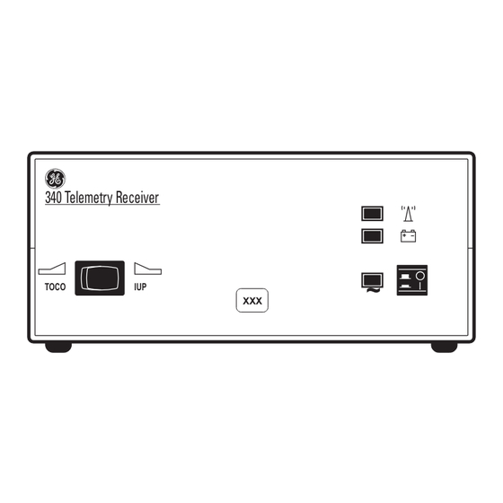
Controls, Indicators, and Connectors: Receiver Receiver Receiver Front Panel 340 Telemetry Receiver TOCO Figure 3-1. Receiver Front Panel Model 340 Telemetry System Revision A 2006920-001... - Page 33 Controls, Indicators, and Connectors: Receiver Table 3-1. Receiver Front Panel Name Description This switch communicates the active uterine activity mode to the fetal or maternal/fetal monitor: UA Mode Selector When monitoring with a tocotransducer, set the Switch switch to the TOCO position. When monitoring with an intrauterine pressure catheter, set the switch to the IUP position.
-
Page 34: Receiver Rear Panel
Controls, Indicators, and Connectors: Receiver Receiver Rear Panel WARNING: TO REDUCE FIRE HAZARD REPLACE FUSE AS MARKED. ANTENNA ULTRASOUND 120V ~ 50-60HZ 30W CONNECT TO COROMETRICS 0.25A SLOW BLOW MONITORS ONLY OUTPUTS TO MONITOR CAUTION Note: Antenna shown removed. Figure 3-2. Receiver Rear Panel Model 340 Telemetry System Revision A 2006920-001... - Page 35 Controls, Indicators, and Connectors: Receiver Table 3-2. Receiver Rear Panel Name Description This module houses the AC-line input connector and the main fuses for the receiver: AC Line Connector and 100–120 VAC: requires two, 0.25 A slow-blow Fuseholder Module fuses. 220–240 VAC: requires two, 0.2 A time-lag fuses.
-
Page 36: Transmitter
Controls, Indicators, and Connectors: Transmitter Transmitter Transmitter Bottom Panel Figure 3-3. Transmitter Bottom Panel Model 340 Telemetry System Revision A 2006920-001... - Page 37 Controls, Indicators, and Connectors: Transmitter Table 3-3. Transmitter Bottom Panel Name Description Connect a Corometrics 5700 Series pulsed Doppler ultrasound transducer to this light gray receptacle. Corometrics 5600 Series continuous-wave Ultrasound Input ultrasound transducers are not compatible with the Model 340 Telemetry System. The 5600 Series Transducer was designed for use with Models 115 and 145 Monitors and Models 320 and 330 Telemetry Systems.
-
Page 38: Transmitter Top Panel
Controls, Indicators, and Connectors: Transmitter Transmitter Top Panel Note: Antenna shown removed. Figure 3-4. Transmitter Top Panel Model 340 Telemetry System Revision A 2006920-001... - Page 39 Controls, Indicators, and Connectors: Transmitter Table 3-4. Transmitter Top Panel Name Description Loops Loops for attaching the carrying strap. Connect the headset to this receptacle to listen to Headset Connector the fetal heart rate derived from ultrasound. Connect a Corometrics Remote Event Marker to this receptacle.
-
Page 40: Transmitter Rear Panel Battery Compartment
Controls, Indicators, and Connectors: Transmitter Transmitter Rear Panel Battery Compartment Battery Compartment Figure 3-5. Transmitter Rear Panel Battery Compartment The battery compartment holds four “AA” alkaline batteries. &$87,21 BATTERY STRENGTH—When the battery power is low, the transmitter emits a chirping sound every 4–5 seconds. -
Page 41: Theory Of Operation
Chapter 4 Theory of Operation This section of the manual contains the electronic theory for the Model 340 Maternal/Fetal Telemetry System. The Model 340 Telemetry System is comprised of a receiver and a transmitter. The electronic theory for the transmitter (Transmitter Board and Transmitter Carrier Board) and receiver (Receiver Board and Receiver Carrier Board) is presented. -
Page 42: Transmitter Board (No. 2003708-001)
Theory of Operation: Transmitter Board (No. 2003708-001) Transmitter Board (No. 2003708-001) Ultrasound The operation of the ultrasound circuitry is controlled by a CMOS programmable logic device (CPLD). This CPLD also contains the active circuitry used to form a 4.604 MHZ crystal oscillator, which is the main system clock from which all board logic timing is derived. - Page 43 Theory of Operation: Transmitter Board (No. 2003708-001) Following the pre-amp is a buffer amplifier and transformer combination. The buffer stage is unity gain and is used to establish a high impedance for the pre-amp output. The transformer converts the single ended pre-amp output to differential for the demodulator that follows.
- Page 44 Theory of Operation: Transmitter Board (No. 2003708-001) The UA circuitry on the Transmitter Board consists of an instrumentation amplifier, a secondary amplifier stage, a voltage- controlled oscillator (VCO), and an active low-pass filter. The instrumentation amplifier is used both to amplify and to convert the differential output of a TOCO bridge or IUP device to single ended.
-
Page 45: Control Circuitry
Theory of Operation: Transmitter Board (No. 2003708-001) Control Circuitry Mode information, along with battery status and remote mark data, is transmitted to the receiving unit by use of individual low-frequency tones. These tones are generated by counters contained within the CPLD and are a division of the main clock. -
Page 46: Power Supply
Theory of Operation: Transmitter Board (No. 2003708-001) Power Supply The main power supply for this system is a boot converter/regulator. This switcher converts the battery voltage to a regulated 6.5 V over a battery range of 3 to 6 V. The switching frequency of this regulator is synchronized to a division of the main clock (575 kHz) to reduce noise that might interfere with operation of the ultrasound circuit. -
Page 47: Telemetry Receiver Board Circuitry (No. 13856A)
Theory of Operation: Telemetry Receiver Board Circuitry (No. 13856A) Telemetry Receiver Board Circuitry (No. 13856A) The RF Receiver The RF receiver used by the Telemetry Receiver Board provides both the encoded modulation from the transmitter, as well as a voltage output that is proportional to the RF signal level received. -
Page 48: Receiver Encoded Modulation
Theory of Operation: Telemetry Receiver Board Circuitry (No. 13856A) Receiver Encoded Modulation The encoded modulation from the receiver is divided into several paths: the first to extract the mode information; the second to extract the data signals. Mode information is removed from the composite signal through a three-pole, active, low-pass filter of 100 Hz. -
Page 49: Toco Channel
Theory of Operation: Telemetry Receiver Board Circuitry (No. 13856A) TOCO Channel The TOCO channel includes an additional three poles of active high-pass filtering at 1.5 kHz, followed by three poles of active low-pass filtering at 2.0 kHz, followed by a 1.75 kHz active two pole band-pass filter with a gain of four. -
Page 50: Ultrasound Channel
Theory of Operation: Telemetry Receiver Board Circuitry (No. 13856A) Ultrasound Channel The ultrasound channel of the receiver consists of the initial 150 Hz high-pass filter, a three-pole active low-pass filter at 550 Hz, a two-pole active low-pass filter at 600 Hz with a gain of four, a three-pole active high-pass filter at 150 Hz, and the last stage of a three-pole active low- pass filter at 500 Hz. -
Page 51: Telemetry Transmitter Carrier Board (2003713-001)
Theory of Operation: Telemetry Transmitter Carrier Board (2003713-001) Telemetry Transmitter Carrier Board (2003713-001) The Transmitter Carrier Board serves as the connection point for devices used by the system. The remote mark, headphones, antenna, and battery pack are all first routed through this board. Additionally, the transmitter RF module and audio piezo speaker are located on this board. -
Page 52: Telemetry Receiver Carrier Board (2004163-001)
Theory of Operation: Telemetry Receiver Carrier Board (2004163-001) Telemetry Receiver Carrier Board (2004163-001) The Receiver Carrier Board houses the RF receiver module. Additional circuitry to add gain to the two receiver outputs (audio and RSSI) are also located on this board. A linear regulator is used to reduce the 12 V from the Receiver Board to the 7.6 V required by the RF module. -
Page 53: Calibration
Chapter 5 Calibration This section of the manual provides a calibration procedure which allows authorized service personnel to perform an instrument alignment using a minimum of test equipment. This procedure is not intended to replace a complete instrument checkout and alignment as performed at the GE Medical Systems Information Technologies factory. -
Page 54: Fcc Service Information
Calibration: FCC Service Information FCC Service Information The UHF Transmitter Module and UHF Receiver Module contained in the Model 340 Telemetry System are GE Medical systems Information Technologies factory service items. ,03257$17 FCC LICENSE—You must have an FCC General Radio... -
Page 55: Test Equipment
Calibration: Test Equipment Test Equipment Testing or calibrating the Model 340 requires the use of properly calibrated, laboratory-class, test equipment. Although the generic equivalents of the test equipment are given in this procedure, the actual equipment selected must have specifications that substantially exceed the tolerance given for each measurement. -
Page 56: Receiver Calibration
Calibration: Receiver Calibration Receiver Calibration Accessing the Receiver Board When viewing the receiver from the top with its cover removed, the Telemetry Receiver Board is located in the bottom section of the receiver chassis. Accessing the Telemetry Receiver Board requires removal of the top cover. -
Page 57: Power Supply
Calibration: Receiver Calibration VOLTS Power Supply When checking the power supply voltages in this section, ensure all voltage checks are within their allowable limits at both low and high AC line voltages. 1. Refer to Table 5-1 and confirm the power supply voltages at the indicated test points. -
Page 58: Toco Channel
Calibration: Receiver Calibration UNITS VOLTS 888 888 888 888 888 888 Hz Generator Hz Counter TOCO Channel 1. Confirm the –3dB points of the band-pass frequency from the input at TP45 to the output at TP29. The lower 3 dB point should measure between 1250 and 1650 Hz. -
Page 59: Ecg Channel
Calibration: Receiver Calibration UNITS VOLTS 888 888 888 888 888 888 Hz Generator Hz Counter ECG Channel 1. Confirm the –3 dB points of the band-pass frequency are at least 2200 Hz and 3000 Hz between the input TP45 and the output TP17. Confirm the filter gain of 2 at center frequency. -
Page 60: Mode Controls
Calibration: Receiver Calibration UNITS VOLTS VOLTS 888 888 888 888 888 888 Hz Generator Hz Counter Mode Controls 1. Confirm the low-pass filter –3 dB cutoff point of 90 ± 6Hz with an input of 1.0 Vp-p at TP45 and the output at TP21. Set R61 for a gain of 2.3. -
Page 61: Rf Carrier Detect
Calibration: Receiver Calibration 6. Refer to Table 5-4. Confirm each tone decoder output locks. The output will go to a logic low state when a 50 mVRMS sine wave of proper frequency is applied to each input at pin 3 of each IC. Table 5-4. -
Page 62: Mode Outputs
Calibration: Receiver Calibration Mode Outputs 1. The mode output signals are generated via open collector transistor switches in U2. For test purposes, the outputs must be connected to a fetal monitor via the US, ECG and UA interconnect cables or pulled up to +5 V (TP5) by 10kΩ... -
Page 63: Ultrasound Modulator
Calibration: Receiver Calibration Ultrasound Modulator 1. Connect a 3 Vp-p 2.3 MHz sine wave signal source into J201 pin 1. Connect J201 pin 8 to ground. Feed a 300 Hz, 1 Vp-p sine wave into J6 pin 2, and set R146 to its mid-position. Adjust L1 for maximum output at TP13. -
Page 64: Transmitter Calibration
Calibration: Transmitter Calibration Transmitter Calibration UA Channel 1. Connect the positive lead of a 0–4 V adjustable DC lab supply to J5 pin 1 (PRESS+) through a 100 KΩ resistor and the negative lead to J5 pin 2 (PRESS–) and J5 pin 6 (GROUND). Jumper a 100 Ω resistor across J5 pin 1 and J5 pin 2. -
Page 65: Main Oscillator
Calibration: Transmitter Calibration Main Oscillator Connect the frequency counter to TP7. Adjust C135 for a frequency of 4.604 MHz ± 5 Hz. Power Supply 1. Confirm –5.6 V ± 0.2 V at TP11 2. Confirm +5.8 V ± 0.2 V at TP10 3. - Page 66 For your notes 5-14 Model 340 Telemetry System Revision A 2006920-001...
-
Page 67: Maintenance
Chapter 6 Maintenance All equipment, no matter how reliable, needs to be maintained on a regular basis. This section describes general care and cleaning instructions for the Model 340 Telemetry System. General Cleaning Precautions......Cleaning the Transmitter and Receiver . -
Page 68: General Cleaning Precautions
Maintenance: General Cleaning Precautions General Cleaning Precautions 127( Refer to your monitor’s &$87,21 operator’s manual for cleaning SHOCK—Unplug the fetal or maternal/fetal monitor and instructions for the monitor and the Model 340R Receiver from the AC power source and transducers. detach all accessories. -
Page 69: Cleaning The Transmitter And Receiver
Maintenance: Cleaning the Transmitter and Receiver Cleaning the Transmitter and Receiver 1. Wipe any fluids from the surface of each unit. 2. Dampen a soft cloth with isopropyl alcohol and gently rub soiled area until clean. 3. Dry with a soft, dry cloth. Revision A Model 340 Telemetry System 2006920-001... - Page 70 For your notes Model 340 Telemetry System Revision A 2006920-001...
- Page 71 Chapter 7 Troubleshooting This section of the manual provides a troubleshooting guide for the most basic Model 340 operational problems. If the response to a specific question is not found, contact the Service Department at one of the following telephone numbers: Call 1-800-558-5120.
-
Page 72: Problem Chart
Troubleshooting: Problem Chart Problem Chart Table 7-1. Troubleshooting Problem Probable Cause Solution Receiver not connected to AC Connect to AC receptacle. Receiver indicator does not light receptacle. Power when the receiver is turned on. Defective AC power cord. Replace AC power cord. Defective AC outlet. - Page 73 Troubleshooting: Problem Chart Table 7-1. Troubleshooting (Continued) Problem Probable Cause Solution Transducer not properly placed. Reposition transducer. Transducer not properly connected to Ensure the transducer is securely transmitter. attached to the transmitter. Receiver interconnection cable(s) not Ensure interconnection cable(s) firmly properly attached.
- Page 74 For your notes Model 340 Telemetry System Revision A 2006920-001...
-
Page 75: Technical Specifications
Chapter 8 Technical Specifications 127( Specifications are subject This section contains a detailed list of the technical specifications for the to change without notice. Model 340 Telemetry System. This chapter lists specifications for the following: Transmitter ........8-2 Receiver. -
Page 76: Transmitter
Technical Specifications: Transmitter Transmitter Table 8-1. Transmitter Category Technical Specifications Physical Characteristics Height: 1.8 in (4.5 cm) Width: 5.4 in (13.8 cm) Depth: 7.5 in (19.0 cm) Weight: 1.75 lbs (0.8 kg) Environmental Conditions Operating Storage Ambient Temperature: 50°F to 104°F (10°C to 40°C) 14°F to 131°F (–10°C to 55°C) Relative Humidity: 5% to 95%, non-condensing... - Page 77 Technical Specifications: Transmitter Table 8-1. Transmitter Category Technical Specifications Antenna Type: Flexible, detachable, BNC interconnect Batteries Type: Four “AA” Alkaline Cells, 6.0 Vdc at 2450 mAh Life: 20 h, approximately Control: On/Off Switch Audio Indicator: Low Battery Connectors: Remote Event Marker Input, Headset Output Use of the headset will deplete the batteries more rapidly Revision A Model 340 Telemetry System...
-
Page 78: Receiver
Technical Specifications: Receiver Receiver Table 8-1. Receiver Category Technical Specifications Power Requirements Nominal Line Voltage: 100–120 VAC 220–240 VAC Line Frequency: 50/60 Hz 50/60 Hz Power Consumption (maximum): 30 W 30 W Chassis Leakage: <50 µ A Physical Characteristics Height: 3.2 in (8.1 cm) Width: 7.4 in (18.8 cm) - Page 79 Chapter 9 Drawings This section of the manual provies the Model 340 schematics and assembly drawings. These drawings should be used in conjunction with other sections in this manual. Revision A Model 340 Telemetry System 2006920-001...
- Page 80 For your notes Model 340 Telemetry System Revision A 2006920-001...
- Page 82 MANUAL P/N 2006920-001 Ê2006920-001ÅŠ...
Need help?
Do you have a question about the Corometrics 340 and is the answer not in the manual?
Questions and answers