Sign In
Upload
Manuals
Brands
GE Medical Systems Manuals
Medical Equipment
Solar 9500
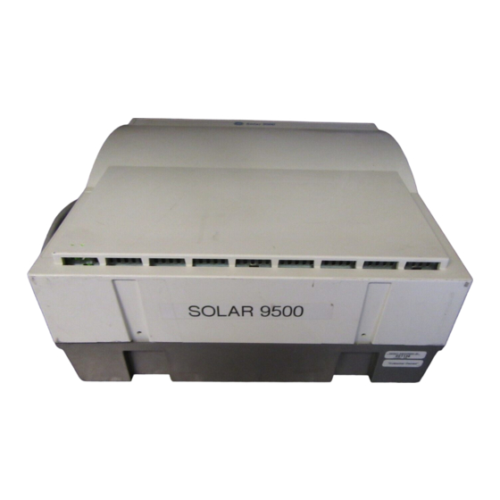
GE Medical Systems Solar 9500 Manuals
Manuals and User Guides for GE Medical Systems Solar 9500. We have
1
GE Medical Systems Solar 9500 manual available for free PDF download: Service Manual
GE Medical Systems Solar 9500 Service Manual (208 pages)
Information Monitor
Brand:
GE Medical Systems
| Category:
Medical Equipment
| Size: 8 MB
Table of Contents
Table of Contents
3
1 Introduction
9
Manual Information
10
Revision History
10
Manual Purpose
10
Intended Audience
10
Safety Information
11
Responsibility of the Manufacturer
11
General
11
Warnings, Cautions, and Notes
12
Equipment Symbols
13
Service Information
14
Service Requirements
14
Equipment Identification
14
2 Overview
15
The Solar 9500 Information Monitor
16
Front View
17
Rear View
17
Interconnection
18
Technical Specifications
19
Supported Devices
23
3 Installation
25
System Components
26
Processing Unit Setup
27
Mounting
28
Installing Cable Shroud
29
Display Descriptions
30
Primary Display
30
Secondary Display
30
Remote Display 1, 2
30
Touchscreen Interface
31
Scrolling Vs. Non-Scrolling Waveforms
31
Browser Support
31
Processing Unit/Display Interconnection
32
Flat Panel Display Interconnection
33
Display Mounting
33
Acquisition Interfaces
34
Tram-Rac Housing
34
Tram-Rac Power Supply Connection
35
Processing Unit/Tram-Rac Interconnection
35
Tram-Rac 2 Housing
35
Tram-Rac 4A Housing
36
Unity Network ID Connectivity Device
36
Dual Tram-Rac Housings
37
About Tram-Net
38
Processing Unit/Rams Interconnection
39
Processing Unit/Polled Parameter Interconnection
40
Local Area Network (LAN) Interfaces
41
About Ethernet
41
Twisted Pair
42
Network Terms
43
Printer Interconnect
44
Laser Printer
44
PRN 50 Digital Writer
46
Connecting to the Unity Network MC Network
47
Connecting to the Unity Network IX Network
48
Keyboard and Mouse
49
Turning Power on
50
Turning Power off
51
Using the Menu Command
51
Alternate Power down Method
51
4 Software Configuration
53
Monitor Service Menu
54
Layout Controls
55
Display/Layout Setup
56
Unit Defaults
59
Printing
64
Controls and Menu Timeouts
66
Module Calibration
67
Bed/Unit Name Setup
67
Serial Interface Controls
68
Network Services
69
Unix Access
69
IP Address
70
Time and Date
72
Audio
73
Diagnostic Messages
73
Locale Settings
74
Creating a Custom Layout
75
Editing Basics for All Customizable Windows
75
Display Features
76
An Overview of Configured Windows
77
Creating a Bed Layout
78
Sample Creation of a Simple Bed Layout
81
Print System Settings
83
Stratification
84
5 Module Calibration
85
General
86
The Service Menu
87
Calibrate Non-Invasive Blood Pressure (NBP)
89
About the Procedure
89
Manufacturer Recommendation
89
Test Equipment
89
Calibration Procedure
90
Calibrate Mainstream CO2
93
About the Procedure
93
Manufacturer Recommendation
93
Test Equipment
93
Calibration Procedure
93
0% CO2 Calibration
94
10% CO2 Calibration
95
Calibration Completion
95
Calibrate Sidestream CO2
96
About the Procedure
96
Manufacturer Recommendation
96
Test Equipment
96
Calibration Procedure
96
0% CO2 Calibration
97
10% CO2 Calibration
98
Calibration Completion
98
Calibrate Barometric Pressure for Interfaced CO2
99
About the Procedure
99
Procedure
99
6 Maintenance
101
Maintenance Schedule
102
Manufacturer Recommendations
102
Manufacturer Responsibility
102
Visual Inspection
103
Cleaning
104
Cleaning Precautions
104
Exterior Cleaning
104
Cleaning the Touch Screen Display
104
Cleaning Inside the Solar 9500 CPU
105
Battery Pack Maintenance
106
Battery Pack Replacement
106
Battery Recycling
108
NLX Motherboard Battery Replacement
109
Electrical Safety Tests
110
General
110
Power Outlet Test
111
Ground (Earth) Integrity
111
Ground (Earth) Wire Leakage Current Tests
113
Enclosure Leakage Current Test
114
Patient (Source) Leakage Current Test
115
Patient (Sink) Leakage Current Test
116
(Mains Voltage on the Applied Part)
116
Test Completion
117
Checkout Procedure
118
Required Tools/Special Equipment
118
Initial Power up
118
Touch Screen Check
119
Speaker Check
119
Tram-Rac Housing Check
119
Tram-Net Communication Check
120
Unity Network MC Network Check
121
Weblink Access Check (Optional Feature)
121
Printer Check (Printer Optional)
121
Unity Network ID Check
121
M-Port Check
122
Completion
122
PM Form
122
Repair Log
123
7 Troubleshooting
125
Fault Isolation
126
First Things to Ask
126
Visual Inspection
126
Main Power and Display Power
128
Fuse Replacement
131
AC Line Voltage Test
133
120 VAC, 50/60 Hz
133
Troubleshooting Procedure
134
Service Menu
134
Diagnostic Messages
135
Log File Types
136
Log File Timestamps
136
Diagnosing System Problems with Houston
137
General
137
Houston Main Menu
137
Overview of the Menu Items
138
Navigating Multi-Page Output
145
8 Theory of Operation
147
Overview
148
Processing Unit Operation
148
Subassemblies
149
Power Supply Assembly
149
Video PCB
151
Riser Interface PCB
153
Riser I/O PCB
155
M-Port PCB
155
Signal Descriptions
157
Power Supply PCB Connectors
157
Video PCB Connectors
160
Riser Interface PCB Connectors
163
Riser I/O PCB Connectors
178
M-Port PCB Connectors
179
9 Field Replaceable Units, Parts Lists and Drawings
183
Ordering Parts
184
Field Replaceable Units
184
Disassembly/Assembly
185
Opening the Unit for Service
185
Replace the Power Supply Assembly
186
Replace the NLX Motherboard
188
Replace Riser I/O PCB Assembly
189
Replace/Add Video PCB or M-Port PCB Assembly
190
Replace NLX Riser Interface PCB Assembly
192
Replace the Hard Drive
193
Upper Level Assembly 901007-003A
200
Power Supply Assembly 419080-001B
204
Advertisement
Advertisement
Related Products
GE Medical Systems 500
GE Medical Systems Corometrics 340
GE Medical Systems Dash 3000
GE Medical Systems Dash 4000
GE Medical Systems LOGIQ 400
GE Medical Systems LOGIQ 500
GE Medical Systems LOGIQ 7
GE Medical Systems LOGIQ 7 Pro
GE Medical Systems LOGIQ ?200
GE Medical Systems LUN7396
GE Medical Systems Categories
Medical Equipment
Treadmill
More GE Medical Systems Manuals
Login
Sign In
OR
Sign in with Facebook
Sign in with Google
Upload manual
Upload from disk
Upload from URL