Table of Contents
Advertisement
Quick Links
Advertisement
Table of Contents

Related Manuals for Procentec ComBricks

Summary of Contents for Procentec ComBricks
- Page 1 User Manual...
- Page 2 Transparent for all PROFIBUS DP protocols ProfiTrace for monitoring 4 networks Drives 32 modules (10 communication modules) Hot swap Powerful web server 100 Mbps Ethernet 12 Mbps PROFIBUS DIN-rail IP 20 ComBricks User Manual v6.4.0 | January 18| © PROCENTEC 2/219...
- Page 3 This product can only function correctly and safely if it is transported, stored, set up, installed, operated and maintained as recommended. ComBricks is a CE class A product. In a domestic environment it may cause radio interference in which case the user may be required to take adequate measures.
-
Page 4: Important Information
Purpose of the Manual This user manual provides information how to work with ComBricks. Recycling and Disposal The parts of the ComBricks can be recycled. For further information about environment-friendly recycling and the procedure for disposing of your old equipment, please contact: PROCENTEC... -
Page 5: Table Of Contents
Configuring repeater modules ......................36 3.10.1 Customizing the PROFIBUS network (NW0/NW1) ................. 36 3.10.2 Redundancy (RED) .......................... 36 3.10.3 Hardware or software settings (H/S) ....................37 3.11 Wiring repeater modules........................ 38 ComBricks User Manual v6.4.0 | January 18| © PROCENTEC 5/219... - Page 6 Audio jack ............................78 Switch navigation of the Head Station 1A/1B/1C ................79 LEDs on the Head Station ....................... 80 7 Repeater modules (RS-485) ................82 Multiple channels per module ......................83 ComBricks User Manual v6.4.0 | January 18| © PROCENTEC 6/219...
- Page 7 PROFIBUS / PROFINET gateway ....................118 11.7 Data consistency ........................... 119 11.7.1 Consistency over 2 bytes ......................120 11.7.2 Consistency over 4 bytes ......................120 11.7.3 Consistency over 8 bytes ......................121 ComBricks User Manual v6.4.0 | January 18| © PROCENTEC 7/219...
- Page 8 18 Tips and Tricks ....................159 18.1 Ident Number lookup ........................159 18.2 Solution for secured email connections ..................159 18.3 IP address adjustment tool ......................159 18.4 Free Wi-Fi channel detector ......................159 ComBricks User Manual v6.4.0 | January 18| © PROCENTEC 8/219...
- Page 9 18.5 Some SNMP tools ......................... 159 19 Technical Data - ComBricks in general ............160 20 Technical Data - Head Station 1A/1B/1C ............161 21 Technical Data - SCOPE Repeater (101-201210) .......... 163 22 Technical Data - 2 Channel Repeater (101-201102) ........165 23 Technical Data - 1 Channel Repeater (101-201101) ........
-
Page 10: Product Description
ProfiTrace and remote I/O. ComBricks is a modular system that allows a mix of automation components on a backplane. Repeater modules can be inserted next to a PROFIBUS slave and at the same time, in a web browser over Ethernet, the condition of the installation can be remotely inspected with ProfiTrace OE. -
Page 11: Modular Profibus Repeaters
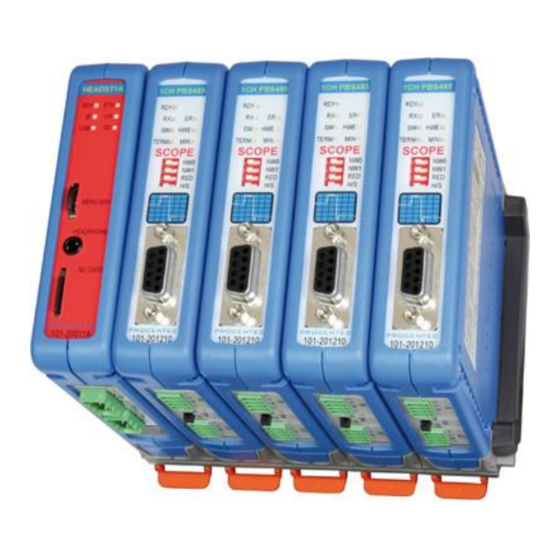
ProfiTrace (see Fig. 1). ComBricks is based on a backplane which can hold up to 10 hot swap repeater modules. Each module has one or two channels (so a total of max 20 galvanic isolated transparent segments). Every channel can handle 31 PROFIBUS stations and maximum 1200 m cable length (depends on the baudrate). -
Page 12: Cable Redundancy
10 parallel cables. This architecture provides extremely high availability. Most suppliers only allow 2 cables (see Fig. 3). Maximum 10 redundant channels redundant channels Fig. 3 - Redundancy configuration example ComBricks User Manual v6.4.0 | January 18| © PROCENTEC 12/219... -
Page 13: Comparison Between Profihub And Combricks
Removable drives and motors • Star, tree and bus structured networks • Motor control centers (drawers) • Redundancy for high availability • EMC vulnerable applications • Spur lines • Isolator for sensitive devices ComBricks User Manual v6.4.0 | January 18| © PROCENTEC 13/219... -
Page 14: Profitrace Oe - Remote Monitoring In A Web Browser
1.5 ProfiTrace OE - Remote monitoring in a web browser Permanent and simultaneous monitoring of 4 PROFIBUS networks is a powerful feature of ComBricks. Global projects and a shortage of (qualified) technical staff members are causing significant capacity problems. ComBricks offers a solution by remotely monitoring PROFIBUS installations over the Internet and alerting the user by email. -
Page 15: Email
1.5.4 Comparison between ComBricks and ProfiTrace 2 The application area for ComBricks (ProfiTrace OE) compared to ProfiTrace 2 is completely different. ProfiTrace OE should be seen as a watchdog and ProfiTrace 2 as the mobile analyzer to do on-site work. -
Page 16: Offshore Applications
1.5.6 Mining applications Because of the depth, gasses and inaccessible areas, ComBricks is required to keep the control room and the experts on a distance to monitor the PROFIBUS installations. Multiple WLAN routers can bring Ethernet up to the surface. -
Page 17: Robot Cells
1.5.8 Logistics In demanding high-speed applications, ComBricks is ideal. The technician does not have to touch the installation and can measure the network from a distance. This is also convenient if the installation is behind a high-security zone such as baggage handling systems at airports, or parcel handling systems. -
Page 18: Traffic Control
1.5.9 Traffic control When distance and downtime are critical factors, ComBricks can be very helpful. Difficult to reach speed indicators above the highway can be monitored from the road-side control cabinet, or even from the control room. Fig. 8 - Traffic control applications 1.5.10 Cranes... -
Page 19: Other Applications
Power switches, hold switches, indicators, backup systems and LED towers are a few examples of machine parts that can be hooked up to the relays. ComBricks is the only monitoring product that has the capability to respond directly on the hardware with multiple relays. -
Page 20: Commdtm
1.7 CommDTM The FREE ComBricks CommDTM offers FDT 1.2 based asset management tools a powerful Ethernet pass- through to access PROFIBUS devices which are connected on ComBricks repeater modules. The internal DP-V1 class 2 masters are able to drive 2 out of 4 networks. When a CommDTM connection is closed, the user can enter another network. -
Page 21: Quick Start
STEP 8: Power the Head Station. (2.6) ComBricks units with Head Stations type 1A are now operational and no further steps have to be taken. For type 1B and 1C Head Stations proceed with the next steps. STEP 9: Insert an Ethernet cable in the Head Station. -
Page 22: Prepare The Backplane
Click in the menu on the left on "IP config". STEP 6: Update the IP settings and confirm it by clicking on "Save" (see Fig. 12). STEP 7: The web page will now reload with the new IP address. ComBricks User Manual v6.4.0 | January 18| © PROCENTEC 22/219... - Page 23 The Notification link name is included in the event emails so that the user can directly jump to the specific ComBricks unit without knowing its local IP number. An example is: www.boiler5.oag.com. The router of the network or the internet server has to reroute this name to an IP number.
-
Page 24: Customizing The Ip Number Through The Discovery Tool
The Discovery Tool works on an enterprise LAN, WLAN and with a direct cable between ComBricks and PC. If you are not sure which ComBricks you are customizing, the LEDs can be flashed with a button in the Discovery tool (flashing). The LEDs will blink for 5 seconds to give the user a visual confirmation. -
Page 25: Checking The Modules And The Administrative Info In The Web Server
On the top of the screen the administrative info is also visible (see Fig. 14). If the administrative information has to be altered, it can be done by clicking on "General config". On the bottom of the screen the connected clients with this ComBricks are displayed. All connections are listed here: •... -
Page 26: Testing Profitrace Oe On The Profibus Installation
Monitoring 4 networks networks networks networks Similar Live List as ProfiTrace 2 Fig. 15 - ProfiTrace OE Live List See Chapter 5 for more information on how to use ProfiTrace OE. ComBricks User Manual v6.4.0 | January 18| © PROCENTEC 26/219... -
Page 27: Resetting The Head Station
2.11 Resetting the Head Station By means of the "Menu Nav" switch on the front of the Head Station (see Fig. 16), ComBricks can be reset, warm started or loaded with configuration data. Please follow the procedure described in Paragraph 6.5. -
Page 28: Installation Instructions
3.3 Mounting and un-mounting backplane units The backplane of the ComBricks has to be mounted on 35 mm DIN-rail with a minimum width of 50 mm to fit a fixed backplane for 2 modules. Fig. 17 illustrates how to mount and dismount the backplane on and from the DIN-rail. For the un-mounting an appropriate screwdriver is required. -
Page 29: Adding Backplane Units
(see Fig. 18). Do not add or remove backplane units while the backplane is powered! This can cause serious damage to the ComBricks set. Fig. 18 - Adding backplane units ComBricks User Manual v6.4.0 | January 18| © PROCENTEC... -
Page 30: Detaching Backplane Units
Do not add or remove backplane units while the backplane is powered! This can cause serious damage to the ComBricks set. STEP 1: Push the top arm down with a screwdriver and delicately pull the top of the backplane unit that has to be removed. -
Page 31: Inserting Modules
To remove a module press the keys on both sides of the module (this has to be done with 2 hands). When both keys are pressed, pull the module out of the slot (see Fig. 21). ComBricks User Manual v6.4.0 | January 18| © PROCENTEC 31/219... -
Page 32: Wiring Ethernet
(green) and reception of data (orange). It is recommended to use a cable/RJ45 plug with grounding/foil due to the nature of industrial applications. The Ethernet interface complies with standard Ethernet guidelines. The maximum cable length from ComBricks to switch/device is 100 meter. - Page 33 The MAC address is printed on the side of the Head Station. Fig. 22 - Wiring Ethernet ComBricks User Manual v6.4.0 | January 18| © PROCENTEC 33/219...
-
Page 34: Power Supply
The RDY LED should be shortly Blinking. • The SD LED should be ON (if an SD card is inserted). • The RDY LED should be ON (also on other inserted Modules). ComBricks User Manual v6.4.0 | January 18| © PROCENTEC 34/219... - Page 35 Redundant power supply option Fig. 23 - Head Station power supply ComBricks User Manual v6.4.0 | January 18| © PROCENTEC 35/219...
-
Page 36: Configuring Repeater Modules
3.10.2 Redundancy (RED) Set this dipswitch to enable the redundancy group for the channel. Redundancy LEFT RIGHT When software settings are preferred this dipswitch does not have to be set. ComBricks User Manual v6.4.0 | January 18| © PROCENTEC 36/219... -
Page 37: Hardware Or Software Settings (H/S)
Network 4: NW0 = R, NW1 = R Network 4: NW0 = R, NW1 = R Redundancy for the current network Dipswitches or web server settings Fig. 24 - Dipswitches and LEDs of the repeaters ComBricks User Manual v6.4.0 | January 18| © PROCENTEC 37/219... -
Page 38: Wiring Repeater Modules
Fig. 25 - Repeater connection topologies (old modules only) Because of the PROFIBUS spur lines limitations it is not recommended to use the screw terminal simultaneously with the DB9 connector. ComBricks User Manual v6.4.0 | January 18| © PROCENTEC 38/219... -
Page 39: Screw Terminals
Pin “B”: Red wire Pin “SH”: Cable shielding OR Pin “I”: Cable shielding Fig. 26 - Use the Dual Ground Clip to connect two PROFIBUS cables in one screw terminal ComBricks User Manual v6.4.0 | January 18| © PROCENTEC 39/219... -
Page 40: Db9 Connector
It is true that the termination is not powered by 5V (which is always required), but better an unpowered termination than nothing at all. ComBricks User Manual v6.4.0 | January 18| © PROCENTEC 40/219... -
Page 41: Web Server
4 Web server To access the web server of ComBricks, open your web browser and enter the IP address that has been setup (after purchase or reset the default IP address is 192.168.1.254). In the Discovery Tool you can find a button to access the web server with the default Windows browser. -
Page 42: Status
The 'User message' with custom messages/info is also displayed here (see Fig. 27). On the top of the screen the network and site info can be inspected (see Fig. 27). On the bottom of the screen the connected clients with this ComBricks are visible (see Fig. 27). Remote... - Page 43 Power redundancy status SD card status Current consumed by the modules Fig. 28 - Example of a module status ComBricks User Manual v6.4.0 | January 18| © PROCENTEC 43/219...
-
Page 44: Channel List
Network filters Show colour legend Inserted network Inserted network modules and the modules and the available channels available channels Communicating devices with Live List colours Fig. 29 - Channel list ComBricks User Manual v6.4.0 | January 18| © PROCENTEC 44/219... -
Page 45: System Log
User or Administrator The system log saves ComBricks events. When this page is accessed all the ComBricks events are displayed. It can be downloaded as text file and cleared/deleted (see Fig. 30). You cannot change the system log in the web server. -
Page 46: General Configuration
& time update. This keeps your ComBricks always set to the right time this option is available in Head Station firmware v1.278 and up). If the ComBricks clock differs more than 10 seconds from the NTP clock, a line in the system log is added. -
Page 47: Network Configuration
Dipswitch settings are always primary to software settings. Customizable network names Hardware or software settings Network selection: 1, 2, 3 , 4 or Not Connected Fig. 32 - Network configuration ComBricks User Manual v6.4.0 | January 18| © PROCENTEC 47/219... -
Page 48: Ip Configuration
The IP Configuration screen offers some basic IP settings. The DHCP functionality can be enabled. If the ComBricks will be connected to a network where a DHCP server is active, the settings can be automatically set into the ComBricks by enabling this feature. The IP address will be set by the DHCP server. -
Page 49: Output Control
Redundant power change or ComBricks failures Fig. 33 - Output Control After power down/up, the ComBricks loads and restores these settings. It is recommended to have a security policy concerning passwords with this feature, because the user is able to control REAL output points. -
Page 50: Password Setup And Login
When only the Administrator login has been activated, the user can always enter the web server without a valid login. When settings need to be altered, the administrator is required to login. ComBricks User Manual v6.4.0 | January 18| © PROCENTEC 50/219... -
Page 51: Password Best Practice
Use different passwords for the Administrator and User. • Never share passwords with anyone. • Always use strong passwords. Avoid: test, 123456, <your company name>, <your first name>, ComBricks, PROCENTEC, etc. • Change passwords immediately if they may have been compromised. -
Page 52: External Protocols
Any FTP client can be used to setup the FTP connection. ComBricks uses port 21. If you have not set a password, ComBricks will accept any password during the connection phase. Some FTP clients require a password, so you can provide any password. -
Page 53: License Update
In case the user wants to update the license of the Head Station, it can be done here via an internet connection or copy the content of a license file. Fig. 35 - License update ComBricks User Manual v6.4.0 | January 18| © PROCENTEC 53/219... -
Page 54: Document Download Page
• There should be an item called "Downloads" on the bottom of the left menu It is possible to replace the PROCENTEC download page with a customized version. Replace index.html with your own version and you can point to directories/files which are located on the SD card. If you are interested in such activities, we recommend you to inspect the structure of the PROCENTEC index.html first. -
Page 55: Email Account Config
V1.253 and higher (email groups since v1.293) Login: Administrator The email account information has to be entered if the user wants to have ComBricks signal events by email. The required information is generally the same as any other email related setup (see Fig. 37). ... -
Page 56: Alive Email
If the test-email has not been received, please check if it has been blocked by a Spam filter. 4.11.1 Alive email ComBricks can send a periodic alive-email to the recipient group(s) entered in the Group: field. If no events are triggered for a longer period, ComBricks will not send emails. This also happens when ComBricks has no connection to the mail server for some reason. -
Page 57: Email Troubleshooting
4.11.2 Email Troubleshooting • Check if ComBricks has access to the internet. You can easily test this by going to the Download page in the ComBricks menu and download a datasheet from the web. • Compare the DNS settings with the requirements of the email server you are using. -
Page 58: Backup Settings To Sd-Card
4.12.4 Clear all data When a ComBricks set has been installed and is ready for normal operation, it may have recorded several events which are not ‘real’ faults. This can happen during wiring or commissioning phase. Press ‘Clear all data’... -
Page 59: Profitrace Oe
The Live List can also generate the product name of the devices when a diagnostic message is captured (synchronized with the GSD library). The button ‘Display Legend’ pops up a window explaining all colours in more detail. ComBricks User Manual v6.4.0 | January 18| © PROCENTEC 59/219... -
Page 60: Updating The Gsd File Library
GSD.BIN, for example the Windows desktop.) STEP 5: GSD.BIN has to be copied to the SD card of the ComBricks. You can do this by inserting it in your PC or FTP (admin account). STEP 6: After inserting the SD card back into the Head Station or closing the FTP session, the GSD information is directly available in the Live List. -
Page 61: Statistics
Here it stops for the technician who is only interested in a quick feedback. The advanced technician can proceed with a message recording and an inspection of the signal quality. ComBricks User Manual v6.4.0 | January 18| © PROCENTEC 61/219... -
Page 62: Message Recording
Because ComBricks is a unit for permanent monitoring, it automatically starts a message recording when an event has been detected. The following event automatically starts a message recording again. -
Page 63: Event Configuration
To reduce an unwanted overload of emails or log entries, the events can be set to Off, Once or Interval. This feature is available in firmware version 1.264 and higher. ComBricks User Manual v6.4.0 | January 18| © PROCENTEC 63/219... -
Page 64: Tag Name Configuration
The interval time can be customized between 1 minute and 365 days. 5.5 Tag name configuration Every ComBricks module and every station in every network can be tagged with a name. Fig. 42 - Tag name configuration screen The first block of tag names is used to assign tags to the ComBricks modules. - Page 65 Tag names of modules are also displayed in drop-down references to modules and in tables on the following pages: • Oscilloscope Images • Oscilloscope Error Images • Oscilloscope configuration • Bar Graphs • PA measurements • Network Configuration • Output Control configuration ComBricks User Manual v6.4.0 | January 18| © PROCENTEC 65/219...
-
Page 66: Oscilloscope Images
The SCOPE repeater is only able to do differential measurements. Selected slots Oscilloscope images of all connected devices behind this SCOPE repeater Fig. 43 - Oscilloscope images from all devices ComBricks User Manual v6.4.0 | January 18| © PROCENTEC 66/219... -
Page 67: Oscilloscope Configuration
This feature (available since firmware version v1.286) makes sure the images are periodically saved to the SD card, so they are not lost in the event of a power-cycle. Every 15 minutes the following images are saved automatically if they need to be updated: ComBricks User Manual v6.4.0 | January 18| © PROCENTEC 67/219... -
Page 68: Oscilloscope Images
Oscilloscope errors Whenever an illegal message is seen by ComBricks, and the message occurred on a module with a Scope, you will be able to find the signal of that illegal message. This is very useful for troubleshooting, because it captures the moment of a failure. - Page 69 16 error images you can click ‘Refresh error images’ to load these. To clear all error messages from memory click ‘Reset scope error images’. ComBricks User Manual v6.4.0 | January 18| © PROCENTEC 69/219...
-
Page 70: Bar Graph
ProfiTrace 2.6.0 or higher • Only 1 ComBricks connection After successfully installing ProfiTrace 2, you can find a 'ProfiTrace v2.x for ComBricks' in the start menu of Windows (see Fig. 48). This is the standard ProfiTrace2.exe, but with an additional parameter; ProfiTrace2.exe" -_CBMODE_ After Starting 'ProfiTrace V2.x for ComBricks' ProfiTrace will initially look very similar to the regular version, but... - Page 71 Start Menu Fig. 48 - Starting ProfiTrace 2 for ComBricks After clicking on the 'Connect ComBricks' button, a mid-screen dialogue window is displayed which is used to setup the connection with ComBricks (see Fig. 49). Available connections...
- Page 72 IP connection. Multiple connection instances can be saved and loaded each with their own connection parameters. ComBricks itself can handle 1 streaming connection, but on the PC multiple ProfiTrace instances can be opened that simultaneously communicate with different ComBricks units.
-
Page 73: Summary Of Statistics And Events
Watchdog has run out on a DP device and the master sends a Data Exchange output telegram. • Non-certified DP devices that do not support a specific service/command or cannot handle a command in time. ComBricks User Manual v6.4.0 | January 18| © PROCENTEC 73/219... - Page 74 PA or FF values such as jitter, DC voltage or DC noise out of range. High/Low signal Fiber Fiber Optic signal is out of range. Optic Ring Failure (fiber Fiber Optic ring is broken. optic) ComBricks User Manual v6.4.0 | January 18| © PROCENTEC 74/219...
-
Page 75: Head Station 1A/1B/1C
6 Head Station 1A/1B/1C The Head Station is the primary element of ComBricks and has to be inserted in the most left slot of the fixed backplane socket. It schedules the interaction between all modules and provides data storage and an Ethernet interface for the user. -
Page 76: Relay Contact
The SD card is hot swappable, but there is a risk that monitoring data is lost when the system wants to write at exactly the same time as the removal or insertion. ComBricks User Manual v6.4.0 | January 18| © PROCENTEC 76/219... -
Page 77: Life Cycle Of The Sd Card
If the maximum number of read and write operations has exceeded the limits, data loss may be possible. 6.3.3 Directories and files The following directories have been standardized for ComBricks and are in most cases located on the SD card; Directories Description... -
Page 78: Audio Jack
6.4 Audio jack Not supported. This connector is removed from hardware versions higher than 1.5. ComBricks User Manual v6.4.0 | January 18| © PROCENTEC 78/219... -
Page 79: Switch Navigation Of The Head Station 1A/1B/1C
5 seconds (L4) IOF Blinking Tap Down/Up USB Blinking LED walk through all Hold Wait the LEDs Warm start up for Done 5 seconds (L5) Tap Down/Up ComBricks User Manual v6.4.0 | January 18| © PROCENTEC 79/219... -
Page 80: Leds On The Head Station
Backplane voltage too low (under 5,5 VDC) or current draw Fast to high (above 2,5 A) Clock-chip error Slow (contact your local Distributor or PROCENTEC) Internal component or firmware error (contact your local Distributor or PROCENTEC) ComBricks User Manual v6.4.0 | January 18| © PROCENTEC 80/219... - Page 81 Module NOT identified USB - Mini USB connecting Blinking No USB connection USB connection SD card Blinking No SD card inserted SD card inserted (activity) SD card inserted (no activity) ComBricks User Manual v6.4.0 | January 18| © PROCENTEC 81/219...
-
Page 82: Repeater Modules (Rs-485)
1CH SCOPE Rep. module module repeater module Rep. (101-201210) (101-201101) (101-201102) (101-201710) (101-201410) Channels Networks Redundancy ProfiTrace (busmonitor) Oscilloscope (bus signals / bargraph) EMC and cable improving Intrinsically safe See chapter 8 ComBricks User Manual v6.4.0 | January 18| © PROCENTEC 82/219... -
Page 83: Multiple Channels Per Module
ProfiTrace OE is able to monitor 4 PROFIBUS networks with 2 units of 2 channel repeater modules. The DB9 connector is connected 1-on-1 to the connectors of channel 1 (see Fig. 50). ComBricks User Manual v6.4.0 | January 18| © PROCENTEC 83/219... -
Page 84: Channel Structure
An extra termination on the connected plug could jeopardize the communication on the segment. See paragraph 3.11 for examples. Fig. 51 - Channel structure of the repeater modules ComBricks User Manual v6.4.0 | January 18| © PROCENTEC 84/219... -
Page 85: Emc Barrier
7.3 EMC barrier The galvanic isolation and bit recovery circuit in the repeater modules, make the ComBricks perfect to act as an EMC barrier for sensitive areas. Fig. 52 - ComBricks as EMC barrier 7.4 Grounding system There are 3 methods to ground the PROFIBUS cable:... -
Page 86: Profibus Dp Cable Specifications
Wire diameter ≥ 0.64 mm Impedance 150 Ohm (3 to 20 MHz) Wire area ≥ 0.32 mm Capacity ≤ 30 pF/m Shielding resistance ≤ 9.5 Ohm/km Loop resistance ≤ 110 Ohm/km ComBricks User Manual v6.4.0 | January 18| © PROCENTEC 86/219... -
Page 87: Profibus Dp Cable Types
• Shipboard cable • Rodent protection cable Flexible cable Robust cable Food cable Hybrid cable Shipboard cable Festoon cable Trailing cable FRNC cable Fig. 54 - Supported PROFIBUS cable types ComBricks User Manual v6.4.0 | January 18| © PROCENTEC 87/219... -
Page 88: Redundancy
ComBricks locks itself to the first redundant channel that has a valid start delimiter. If this channel does not have valid telegrams anymore, ComBricks locks itself to the next redundant channel with a valid start delimiter. There is no logic which redundant channel is selected. -
Page 89: Mixing With Other Repeaters
If you mix ComBricks with other repeaters you only have to follow the cascading rules of the other repeater manufacturer. If the other repeaters are also from PROCENTEC, you can cascade and mix without problems. -
Page 90: Leds Of The Repeater Module
(< 2.5 V) TERM Valid idle voltage Idle voltage is too low (~ 1 V). (< 1 V) Repeater is Internal repeater operational. error (contact PROCENTEC) ComBricks User Manual v6.4.0 | January 18| © PROCENTEC 90/219... -
Page 91: Rs-485-Is Barrier Module
As an alternative it can also be used as a busmonitor on existing IS segments created by 3rd party barriers. The IS barrier can be mixed on the backplane with other ComBricks modules, such as the PROFIBUS PA, Fiber Optic and regular RS-485 modules. -
Page 92: Compliancy And Certificates
The RS-485-IS Barrier module complies with: II (2) G [Ex ia Gb] IIC EN-IEC60079-0: 2009 EN-IEC60079-11: 2012 EN-IEC60079-25: 2010 PROFIBUS International IS Installation Guidelines Certification number: DEKRA 12ATEX019 Fig. 56 - Dekra ATEX Certificate ComBricks User Manual v6.4.0 | January 18| © PROCENTEC 92/219... -
Page 93: Channel Structure
If by accident the Direct Grounding is connected with the Indirect Grounding, the Direct Grounding “wins”. 8.5 Baudrate detection Refer to paragraph 7.5 for a description of the baudrate detection. ComBricks User Manual v6.4.0 | January 18| © PROCENTEC 93/219... -
Page 94: Profibus Dp Cable Lengths
Wire diameter ≥ 0.64 mm Impedance 135..165 Ohms at 3..20 MHz Wire area ≥ 0.34 mm Capacity ≤ 30 pF/m Shielding resistance ≤ 9.5 Ohm/km Loop resistance ≤ 110 Ohm/km ComBricks User Manual v6.4.0 | January 18| © PROCENTEC 94/219... -
Page 95: Leds And Dip Switches Of The Repeater Module
Network 4: NW0 = R, NW1 = R Dipswitches or web server settings Redundancy for the current network 8.9 Redundancy Refer to paragraph 7.9 for a description of the redundancy system. ComBricks User Manual v6.4.0 | January 18| © PROCENTEC 95/219... -
Page 96: Fiber Optic Module (2Fo-001)
ProfiTrace OE core in the Head Station. Busmonitor data is directly available in the web server. ComBricks can easily be transformed to a fully dedicated fiber optic hub mixed with copper segments. The hub topology delivers an optimized delay time and live expansion. -
Page 97: Bus Topology With Combricks
High availability 9.2 Delay time Fiber optic applications require a delay time calculation to adjust the Slottime busparameter in the configuration of the master(s). ComBricks complies with the following formulas: −6 FO cable delay = ( 5 ∗ 10 ) × FO cable length × Baudrate Example: 1.5 Mbps, 3 km FO cable... -
Page 98: Baudrate Detection
9.5 Use of FO modules in combination with other brands When it is required that the ComBricks module connects to a third party optical link module, make sure to enable the ‘Compatibility mode’ on the third party optical link. This will ensure normal operation. -
Page 99: Fiber Optic Ring Module (For-Mm1 / Sm1 / Xm1)
Firmware version v1.288 or higher is required to run these modules. Please update your firmware before using the Fiber Optic Ring modules. 10.1 Topologies The ComBricks Fiber Optic Ring Module supports many topologies: Multimode Ring Single mode Ring Mixed mode Ring... -
Page 100: Delay Time
= Number of fiber optic modules in ring FO-modules = Delay of one fiber optic module (see table) delay The above formula can be completed with the values in the following table: ComBricks User Manual v6.4.0 | January 18| © PROCENTEC 100/219... - Page 101 450 + (3 x 120) + (10 x 43) 450 + 360 + 430 = 1240 bit times It is required to change the T to a value higher than 1240. slot ComBricks User Manual v6.4.0 | January 18| © PROCENTEC 101/219...
-
Page 102: Dipswitches
NU = not used In all ring redundancy modes, the Ring dipswitches must be switched to the LEFT position. In case both channels are connected in line mode (to two different ComBricks FO modules), disable the RED switch (switch to RIGHT). -
Page 103: Leds
On the module status page all vital module information is displayed. You can see the detected baudrate, and channel 1 and 2 signal status. Also the ring status is displayed. ComBricks User Manual v6.4.0 | January 18| © PROCENTEC 103/219... - Page 104 Signal and ring status These statuses are monitored by the ComBricks webserver and can be used as triggered events. To set up the triggered event go to the ‘Fiber optic config’ page as shown in Fig. 59 and Fig. 60.
- Page 105 If the ring fails, this is a trigger. You can choose to have a trigger also on ring reconnection. To set this up, choose ‘All changes’ in the Ring Status Events setting. See paragraph 4.7 and 5.4 for Output Control and Event Configuration to enable the Fiber Optic events. ComBricks User Manual v6.4.0 | January 18| © PROCENTEC 105/219...
-
Page 106: Profibus Slave Module Pbs-001
11 PROFIBUS Slave Module PBS-001 The PBS-001 PROFIBUS slave module enables your ComBricks set with real Remote I/O capabilities. A unique feature is that it can also be used as a DP/DP coupler, a PB/PN coupler or gateway between multiple PROFIBUS and/or PROFINET networks. -
Page 107: Rdy Led
PBS-001 module is in Data Exchange with a PROFIBUS master. (red) PBS-001 module is not in Data Exchange with a PROFIBUS master. 11.1.3 Dipswitches The PBS-001 has four dipswitches, located on the bottom ComBricks User Manual v6.4.0 | January 18| © PROCENTEC 107/219... - Page 108 Network 2: NW0 = R, NW1 = L Network 3: NW0 = L, NW1 = R Network 4: NW0 = R, NW1 = R Not used Dipswitches or web server settings Fig. 61 - Dipswitch descriptions ComBricks User Manual v6.4.0 | January 18| © PROCENTEC 108/219...
-
Page 109: Quick Start Checklist
11.3 Setting up the slave module Before inserting the module into your ComBricks set, first decide if you want to use the hardware address or if you want to use software addressing. Also decide to which network it listens by selecting the correct network number (see paragraph 3.10.1). -
Page 110: Hardware Addressing
The addressable range is 1 to 99. Examples: Rotary 10x: Rotary 1x: Resulting address: Software addressing (see 11.3.2) Now the module can be inserted in an empty backplane slot as described in paragraph 3.6. ComBricks User Manual v6.4.0 | January 18| © PROCENTEC 110/219... -
Page 111: Software Addressing
If the Lock feature was used in setting the address, the station address can only be unlocked if the PBS-001 is powered down and then powered up while the two rotary switches are NOT set to 0. This resets the software address to 126. ComBricks User Manual v6.4.0 | January 18| © PROCENTEC 111/219... -
Page 112: Remote I/O Mode
PLC. Refer to the manual of the supplier of your configuration tool for instructions for that tool. This example, a typical ComBricks setup with remote I/O, is built up as follows (see Fig. 63) Fig. 63 - ComBricks configuration screenshot of the web server The first two slots are occupied by Scope Repeater modules, then a Slave PBS-001, then an 8DO module followed by a 4 Relay module. - Page 113 ProfiTrace (see Fig. 66). Fig. 65 - Slave indicating External Diagnostics Fig. 66 - Diagnostics from the GSD in the Info Panel of ProfiTrace ComBricks User Manual v6.4.0 | January 18| © PROCENTEC 113/219...
-
Page 114: Strict Check Configuration
Use the correct GSD file. In case of failure of the master, cable, ComBricks Headstation or backplane, the outputs of the ComBricks modules can be set to a failsafe state. This happens after a certain time-out period during which the slave did not receive any telegram from its master. -
Page 115: Input Test Patterns
Use the correct GSD file. The input modules of ComBricks can be set to a test mode. Different test patterns can be generated automatically for testing purposes, for example during a commissioning or FAT/SAT phase, to see if the PLC is programmed correctly. - Page 116 After selecting a simulation pattern, you can enter a decimal value of 0 to 255 in the Simulation Timer box. This value indicates the waiting time in seconds before the input changes to the next value. ComBricks User Manual v6.4.0 | January 18| © PROCENTEC 116/219...
-
Page 117: Dp/Dp Coupling Or Gateway Mode
For each network a PBS-001 is needed. So if you wish to connect 2 networks, you need 2 PBS-001 modules in one ComBricks set. A typical ComBricks configuration for a DP/DP setup may look like Fig. 70:... -
Page 118: Profibus / Profinet Gateway
It does not matter if these networks are PROFIBUS or PROFINET. Network 1 Network 2 12 Mbit 500 kbps Network 3 Fig. 74 - Example network layout of two PROFIBUS and one PROFINET networks ComBricks User Manual v6.4.0 | January 18| © PROCENTEC 118/219... -
Page 119: Data Consistency
The example shows how to transfer consistent data from network 2 to network 1. If the data is consistent, nothing happens. If the data is not consistent, this is visualized by incrementing the outputs of the 8DO card (assigned to network 1). ComBricks User Manual v6.4.0 | January 18| © PROCENTEC 119/219... -
Page 120: Consistency Over 2 Bytes
Configuration of Network 1: Configuration of Network 2: Data Block 1 of Network 1: Data Block 1 of Network 2: Organization Block 1 of Network 1: Organization Block 1 of Network 2: ComBricks User Manual v6.4.0 | January 18| © PROCENTEC 120/219... -
Page 121: Consistency Over 8 Bytes
Configuration of Network 1: Configuration of Network 2: Data Block 1 of Network 1: Data Block 1 of Network 2: Organization Block 1 of Network 1: Organization Block 1 of Network 2: ComBricks User Manual v6.4.0 | January 18| © PROCENTEC 121/219... -
Page 122: Pa Link/Coupler Module
The free CommDTM allows access for asset management tools over Ethernet. ComBricks is able to carry 9 PA links and an RS-485 or Fiber Optic module. It can also be a customized mix of PA modules with other communication modules. The PA link provides 500 mA current on a customizable bus voltage. -
Page 123: Quick Start Checklist
This checklist lists all the steps to a quick usage of the PA module in Link or Coupler mode. It is assumed that a running ComBricks set with at least one DP repeater module or fiber optic coupler module is already active. -
Page 124: Monitoring Mode
If the module is used in Monitoring Mode, make sure to set the Network Selection to a different network than networks already used by the ComBricks set. See paragraph 3.10.1 for an explanation how to do this. If the module is set to the same network, all PA messages will also be transmitted on the DP network! This will cause errors. -
Page 125: Pa Oscilloscope Images
Fig. 82 - Bargraph image for PA In the above example the amplitude is too high due to missing termination on one side. Normally the amplitude should be between 750 and 1000 mV. ComBricks User Manual v6.4.0 | January 18| © PROCENTEC 125/219... -
Page 126: Pa Measurements
The DC noise indicates how much the voltage of the signal varies. If the noise is too high it can influence the communication; it should not exceed 100 mV. Select the correct slot and the station address of the PA slave Measurements Measurements Measurements Fig. 83 - PA measurements ComBricks User Manual v6.4.0 | January 18| © PROCENTEC 126/219... -
Page 127: Oscilloscope Configuration
PA Bar Graph, and are used for e-mail alarms, logging and output control (see paragraphs 0 and 5.4). Module specific settings Fig. 84 - Oscilloscope configuration ComBricks User Manual v6.4.0 | January 18| © PROCENTEC 127/219... -
Page 128: Link Mode (Module Firmware V2.10.1 And Higher Only)
To receive telegrams from a PLC or DCS in Link mode, you need to install another module in the ComBricks backplane. This module can be any PROFIBUS DP interface card, either fiber optic or copper. All modules in chapters 7, 8 and 9 can be used. Set this DP card to the same network as the PA module. -
Page 129: Coupler Mode
To receive telegrams from a PLC or DCS in Coupler mode, you need to install another module in the ComBricks backplane. This module can be any PROFIBUS DP interface card, either fiber optic or copper. All modules in chapters 7, 8 and 9 can be used. Set this DP card to the same network as the PA Coupler module. -
Page 130: Physical Layer
It is also possible to use the second connector as a stub line, as shown in Fig. 87. Do not terminate the end of a stub line, otherwise the PA segment has too many terminations. ComBricks User Manual v6.4.0 | January 18| © PROCENTEC 130/219... -
Page 131: Cable Specifications
Impedance (31,25 kHz) 100 Ohm ±20% Attenuation (39 kHz) 3 dB/km Capacitive asymmetry 2 nF/km Max. propagation delay change (7.9 to 39 kHz) 1.7 µsec/km Max. shield coverage Cable length 1900 m ComBricks User Manual v6.4.0 | January 18| © PROCENTEC 131/219... - Page 132 ComBricks User Manual v6.4.0 | January 18| © PROCENTEC 132/219...
-
Page 133: Spur Lines
+ .. + I = Total current in a segment = Basic current of devices = Current of the Fault Disconnection Electronics See Fig. 88 for an example. ComBricks User Manual v6.4.0 | January 18| © PROCENTEC 133/219... -
Page 134: Voltage At The End Of The Segment
Fig. 89 - Example of voltage calculation at the end of the cable In this example the voltage at the end of the cable is 24 V - (0.05A * 44 * 1.5) = 20.7 V ComBricks User Manual v6.4.0 | January 18| © PROCENTEC 134/219... -
Page 135: Profinet Device Pnd-001
PN/DP couplers. Configurations from the GSD file define the data area between the modules. ComBricks has the advantage that 10 PROFINET modules can cross exchange information. When the PROFINET Device has to publish I/O modules, the configuration steps are the same as any PROFINET device. -
Page 136: Status Leds
(max 1 minute). Flashing A backplane firmware update of the PND-001 module is executed by the Head (0.3Hz) Station (max 1 minute). The connection with the Head Station is established. ComBricks User Manual v6.4.0 | January 18| © PROCENTEC 136/219... -
Page 137: Profinet Leds
The PROFINET Controller is switched off Remedy: • Check the configuration and assign a valid device name to the PND-001 module. • Check the PROFINET Controller. No physical link. Remedy: check the cable and switch. ComBricks User Manual v6.4.0 | January 18| © PROCENTEC 137/219... -
Page 138: Quick Start Checklist
STEP 1: Provide the Head Station 1B or 1C with the latest firmware, at least v1.272. STEP 2: Add at least two empty backplane slots to the ComBricks set. (2.2) STEP 3: Use the rotary switch on the bottom to assign a custom or pre-defined name to the PROFINET device. -
Page 139: Identification And Name Assignment
Fig. 90 - Assigning a new device name Fig. 91 - New device name options The checkbox ‘Permanent value’ should be enabled if you wish to save the name to non-volatile memory. ComBricks User Manual v6.4.0 | January 18| © PROCENTEC 139/219... -
Page 140: Assigning A Pre-Defined Name
PLC. Refer to the manual of the supplier of your configuration tool for instructions for that tool. This example, a typical ComBricks setup with remote I/O, is built up as follows (see Fig. 92). Fig. 92 - Example configuration for Remote I/O The first slot is occupied by the PND-001 module, and next to it are an 8DO and Relay module. -
Page 141: Pn/Pn Coupling Or Proxy Mode
I/O level, where you can decide how many bytes need to be transferred. For each network a PND-001 is needed. So if you wish to connect 2 networks, you need 2 PND-001 modules in one ComBricks set. A typical ComBricks configuration for a PN/PN setup may look like this: Example layout Network 1 i 10..13... -
Page 142: Profinet / Profibus Proxy
Fig. 97 - Example network layout of two PROFINET and one PROFIBUS networks The configuration of the networks is as follows: Fig. 98 - Configuration for PROFINET network 1 Fig. 99 - Configuration for PROFINET network 2 ComBricks User Manual v6.4.0 | January 18| © PROCENTEC 142/219... - Page 143 Fig. 100 - Configuration for the PROFIBUS network Now the inputs and Outputs of all networks can be sent to the I/O of the proxies in the PLC programs. ComBricks User Manual v6.4.0 | January 18| © PROCENTEC 143/219...
-
Page 144: Commdtm
Please note: It is not possible to use a Siemens DP/PA link to send DTM commands from DP to PA. Only the ComBricks PA module can send DTM commands on PA. To achieve this when using a Siemens Link, refer to paragraph 12.2 and setup the PA module in Monitoring mode. -
Page 145: Using The Commdtm
Fig. 101 - Setting up the PCD server Next, select this location again and click ‘Setup’. Enter the correct IP address of the ComBricks Head Station, and choose the port and network you wish to connect to. Depending on the password settings in the ComBricks, you might also have to fill in a username and password. - Page 146 ComBricks and PCD icons appear in the system tray: In PACTware, make sure to set the correct bus parameters by right-clicking the PROCENTEC DP-V1 master and choose ‘Parameters’. Enter the correct parameters or select ‘Start’ to auto-detect these (see Fig. 103). Then click ‘OK’.
- Page 147 Quiet time: only required in case of heavy reflections. After you have correctly applied these steps, the ComBricks is now a DP-V1 master and ready for communication to field devices. For a detailed walk-through refer to the Download section of the PROCENTEC website for a comprehensive Quick Start for PACTware and FieldCare.
-
Page 148: Opc
15 OPC OPC functionality in ComBricks is available in the following way: By opening a stream from the ComBricks Headstation to a PC in the local network, all PROFIBUS messages are sent to this computer. This PC has ProfiTrace running, and in ProfiTrace the OPC server is active. So the actual OPC server is inside ProfiTrace, not in the Headstation. -
Page 149: Setting Up A Stream
15.2 Setting up a stream To connect the ComBricks to ProfiTrace, see paragraph 5.8. 15.3 Selecting OPC tags The OPC tag settings can be found in the Settings menu (see Fig. 105). Select Setup OPC Tag Settings Fig. 105 - OPC tags in the Settings menu In the next dialog you can add tags (see Fig. -
Page 150: Activating The Opc Server
The OPC server settings can be found in the Settings menu (see Fig. 107). In the next dialog the server can be added (see Fig. 108). A maximum of 16 servers can be created, each with its own tag groups. ComBricks User Manual v6.4.0 | January 18| © PROCENTEC 150/219... - Page 151 Also choose a ComBricks connection. When the settings are completed click “close” and the OPC server will be active. In later stages the OPC server settings can be modified. ComBricks User Manual v6.4.0 | January 18| © PROCENTEC 151/219...
- Page 152 ProfiTrace in system tray only Ready! Fig. 109 - OPC server properties From this point any application that has the availability of an OPC client can access the ProfiTrace OPC tags. ComBricks User Manual v6.4.0 | January 18| © PROCENTEC 152/219...
-
Page 153: Snmp
The Headstation has a powerful feature, SNMP, available free of charge in every Headstation version. With SNMP you can retrieve any data via Ethernet that has been collected by the ComBricks system. This SNMP data can be used by network management tools or SCADA systems to visualize the collected data. -
Page 154: Viewing The Mib File
4. Go back to the tab ‘Tree’ and click the setup button . 5. Enter a name for the profile and enter the IP address of the target ComBricks. Use default SNMP port 161 and other default settings. Then click OK. - Page 155 Fig. 110 - Example of reading SNMP data The info panel of SNMPb shows the description and details of the selected SNMP item. For other freeware SNMP tools, see Paragraph 18.5. ComBricks User Manual v6.4.0 | January 18| © PROCENTEC 155/219...
-
Page 156: Firmware Updates
The Firmware Update procedure requires a power-down of the ComBricks system. Modules will not be active during the update sequence. This means that the repeater functionality of the ComBricks is disabled and (parts of) the network will be down. - Page 157 USB to the .pkg file and in the update mode This window can be closed directly, but wait until COMbricks is ready (check LEDs) Fig. 112 - Firmware update tool ComBricks User Manual v6.4.0 | January 18| © PROCENTEC 157/219...
-
Page 158: Updating Modules
17.2 Updating modules Some ComBricks modules can get new functionality by updating the module firmware. These updates are not distributed through the Head Station firmware, but in separate Module firmware packages. For a listing of all available firmware, see www.procentec.com/ComBricks. -
Page 159: Tips And Tricks
18.3 IP address adjustment tool Every time you go 1-on-1 with a laptop to a ComBricks unit, the IP settings of your laptop have to be adjusted to fit the local IP address of the ComBricks. To make this step very easy a tool is available with the name NetSetMan to automatically change all the settings according to customized profiles. -
Page 160: Technical Data - Combricks In General
Colours and material Housing RAL 5017 (blue) - ABS Backplane RAL 7037 (grey) - ABS DIN rail clip RAL 2004 (orange) - PP Side cap RAL 7024 (anthracite) - PP ComBricks User Manual v6.4.0 | January 18| © PROCENTEC 160/219... -
Page 161: Technical Data - Head Station 1A/1B/1C
9C.B2.06.xx.xx.xx (label on the side of the Head Station) Supported protocols HTTP, FTP, SMTP, TELNET, DHCP, SNMP Default IP address after reset/purchase 192.168.1.254 Connections 20 simultaneous web server clients Relay contact ComBricks User Manual v6.4.0 | January 18| © PROCENTEC 161/219... - Page 162 Class 2 power supply, or equivalent. SD Card Types SD and SDHC Size Max. 32 GB (1 GB is provided) Others Weight 150 g MTBF To be defined ComBricks User Manual v6.4.0 | January 18| © PROCENTEC 162/219...
-
Page 163: Technical Data - Scope Repeater (101-201210)
Maximum 31 devices per channel (busloads) Termination Integrated (switchable - PB RS-485 - 390/220/390 Ohms) Cascading depth No limit, only busparameter limitation of the master Redundancy Yes, maximum 10 cables activated by switch ComBricks User Manual v6.4.0 | January 18| © PROCENTEC 163/219... - Page 164 The alarm values be changed through the web server. Others Head Station firmware At least version 1.260 Operating temperature 0 .. 60 °C Weight 120 g MTBF To be defined ComBricks User Manual v6.4.0 | January 18| © PROCENTEC 164/219...
-
Page 165: Technical Data - 2 Channel Repeater (101-201102)
100 m at 3 Mbps .. 12 Mbps Wire diameter (for the screw terminals) < 2.5 mm Wire type Stranded or solid core Number of devices Maximum 31 devices per channel (busload) Termination Integrated (switchable) ComBricks User Manual v6.4.0 | January 18| © PROCENTEC 165/219... - Page 166 Screw terminals + DB9 connector (1-on-1) A, B Green wire, Red wire Direct grounding Indirect grounding Others Head Station firmware Operating temperature 0 .. 60 °C Weight 125 grams MTBF To be defined ComBricks User Manual v6.4.0 | January 18| © PROCENTEC 166/219...
-
Page 167: Technical Data - 1 Channel Repeater (101-201101)
100 m at 3 Mbps .. 12 Mbps Wire diameter (for the screw terminals) < 2.5 mm Wire type Stranded or solid core Number of devices Maximum 31 devices per channel (busloads) Termination Integrated (switchable) ComBricks User Manual v6.4.0 | January 18| © PROCENTEC 167/219... - Page 168 Screw terminals + DB9 connector (1-on-1) A, B Green wire, Red wire Direct grounding Indirect grounding Others Head Station firmware Operating temperature 0 .. 60 °C Weight 110 grams MTBF To be defined ComBricks User Manual v6.4.0 | January 18| © PROCENTEC 168/219...
-
Page 169: Technical Data - Fiber Optic Module (101-201510)
Total delay between 2 modules (2 directions) Continued example: 1.5 Mbps, 22.5 TBit FO delay: Tdelay = (22.5 + ( 2 × 1.8 ) ) × 2 = 52.2 TBit ComBricks User Manual v6.4.0 | January 18| © PROCENTEC 169/219... - Page 170 Network 4: NW0 = R, NW1 = R server settings LEFT Hardware RIGHT Software Others Head Station firmware 1.264 and higher Operating temperature 0 .. 60 °C Weight 121 g MTBF To be defined ComBricks User Manual v6.4.0 | January 18| © PROCENTEC 170/219...
-
Page 171: Technical Data - Fiber Optic Ring Mm1 (101-201530)
Optical budget 13dB Optical Loss 2dB per km Connectors 4 x ST/BFOC (2 channels) Topologies Ring, point-to-point (direct, hub, split, star) Cascading depth No limit, only busparameter limitation of the master ComBricks User Manual v6.4.0 | January 18| © PROCENTEC 171/219... - Page 172 No errors, or channel No baudrate detected is off. or no connection/signal Others Head Station firmware 1.288 and higher Operating temperature 0 .. 60 °C Weight 121 g MTBF To be defined ComBricks User Manual v6.4.0 | January 18| © PROCENTEC 172/219...
-
Page 173: Technical Data - Fiber Optic Ring Sm1 (101-201531)
Optical budget 17dB Optical loss 0.4dB per km Connectors 4 x ST/BFOC (2 channels) Topologies Ring, point-to-point (direct, hub, split, star) Cascading depth No limit, only busparameter limitation of the master ComBricks User Manual v6.4.0 | January 18| © PROCENTEC 173/219... - Page 174 No errors, or channel No baudrate detected is off. or no connection/signal Others Head Station firmware 1.288 and higher Operating temperature 0 .. 60 °C Weight 121 g MTBF To be defined ComBricks User Manual v6.4.0 | January 18| © PROCENTEC 174/219...
-
Page 175: Technical Data - Fiber Optic Ring Xm1 (101-201532)
Multimode: 2dB per km Single mode: 0.4dB per km Connectors 4 x ST/BFOC (2 channels) Topologies Ring, point-to-point (direct, hub, split, star) Cascading depth No limit, only busparameter limitation of the master ComBricks User Manual v6.4.0 | January 18| © PROCENTEC 175/219... - Page 176 No errors, or channel No baudrate detected is off. or no connection/signal Others Head Station firmware 1.288 and higher Operating temperature 0 .. 60 °C Weight 121 g MTBF To be defined ComBricks User Manual v6.4.0 | January 18| © PROCENTEC 176/219...
-
Page 177: Technical Data - Salt Repeater (101-201710)
Stranded or solid core Number of devices Maximum 31 devices per channel (busloads) Cascading depth No limit, only busparameter limitation of the master Redundancy Yes, maximum 10 cables activated by switch Termination ComBricks User Manual v6.4.0 | January 18| © PROCENTEC 177/219... - Page 178 Alarm values can be changed through the web server. Others Head Station firmware At least version 1.264 Operating temperature 0 .. 60 °C Weight 120 g MTBF To be defined ComBricks User Manual v6.4.0 | January 18| © PROCENTEC 178/219...
-
Page 179: Technical Data - Pa Module (101-201610)
Address NO bus address required (Link has address 1 on PA) Supported Protocols DP-V0, DP- V1, DP-V2, FDL, MPI, FMS, PROFIsafe, PROFIdrive and any other FDL based protocol Oscilloscope specifications ComBricks User Manual v6.4.0 | January 18| © PROCENTEC 179/219... - Page 180 Alarm values can be changed through the web server. Others Head Station firmware At least version 1.279 Operating temperature 0 .. 60 °C Weight 133 g MTBF To be defined ComBricks User Manual v6.4.0 | January 18| © PROCENTEC 180/219...
-
Page 181: Technical Data - 4 Ch Relay Module (101-210210)
Stranded or solid core Others Head Station firmware V1.260 and later Dimensions 140 x 110 x 25 mm Operating temperature 0 .. 60 °C Weight 125 g MTBF To be defined ComBricks User Manual v6.4.0 | January 18| © PROCENTEC 181/219... -
Page 182: Technical Data - 8 Ch D-Out Module (101-210110)
Stranded or solid core Others Head Station firmware V1.260 and later Dimensions 140 x 110 x 25 mm Operating temperature 0 .. 60 °C Weight 105 g MTBF To be defined ComBricks User Manual v6.4.0 | January 18| © PROCENTEC 182/219... -
Page 183: Technical Data - 8 Ch D-In Module (101-210010)
Head Station firmware V1.271 and later Dimensions (L x W x H) 140 x 110 x 25 mm Operating temperature 0 .. 60 °C Weight 100 g MTBF To be defined ComBricks User Manual v6.4.0 | January 18| © PROCENTEC 183/219... -
Page 184: Technical Data - Rs-485-Is Barrier (101-201410)
200 m at 1.5 Mbps Number of devices Maximum 31 devices per channel (busloads) Required termination DB9-IS connector with internal 200Ω only Redundancy Yes, maximum 10 cables activated by switch Dipswitches ComBricks User Manual v6.4.0 | January 18| © PROCENTEC 184/219... - Page 185 Alarm values can be changed through the web server. Others Head Station firmware At least version 1.272 Operating temperature 0 .. 60 °C Weight 150 g MTBF To be defined ComBricks User Manual v6.4.0 | January 18| © PROCENTEC 185/219...
-
Page 186: Technical Data - Profibus Slave Module Pbs-001
Maximum 31 devices per channel (busloads) Cable lengths 1200 m at 9.6 kbps .. 93.75 kbps 1000 m at 187.5 kbps 400 m at 500 kbps 200 m at 1.5 Mbps ComBricks User Manual v6.4.0 | January 18| © PROCENTEC 186/219... - Page 187 Bus Failure: not in Data error Exchange Exchange with master Others Head Station firmware At least version 1.275 Operating temperature 0 .. 60 °C Weight 120 g MTBF To be defined ComBricks User Manual v6.4.0 | January 18| © PROCENTEC 187/219...
-
Page 188: Technical Data - Profinet Device Pnd001
Transmission speed detection Auto detect, Auto cross-over, Auto polarity Cable length Max. 100 m Connectors RJ-45 • 90 Degree connector for port 1 is not recommended. • Shielded connectors are recommended. ComBricks User Manual v6.4.0 | January 18| © PROCENTEC 188/219... - Page 189 Manufacturer / Product Ident Number 0x4000 hex - 0x0001 hex Others Head Station firmware Version 1.264 or higher Operating temperature 0 .. 60 °C Weight 111 g MTBF To be defined ComBricks User Manual v6.4.0 | January 18| © PROCENTEC 189/219...
-
Page 190: Technical Data - 6A Power Module T1 (101-230010)
No power supply connected Others Head Station firmware At least version 1.265 Dimensions (L x W x H) 140 x 110 x 25 mm Operating temperature 0 .. 60 °C Weight 125 g ComBricks User Manual v6.4.0 | January 18| © PROCENTEC 190/219... -
Page 191: Frequently Asked Questions / Faq
Are the Kits in the product list really required? NO, the Kits are just an easy step into the ComBricks world, because they contain all required components. You can also order all items separately; Head Station, repeater modules, I/O modules, etc. Kits are also cheaper than separate items. - Page 192 Do I need to install/buy monitoring software? NO, ComBricks is based on a web server. For the basic operation you only need a web browser. But if you are used to the ProfiTrace 2 software, you can stream data over Ethernet and keep working in your original software environment.
- Page 193 Can ComBricks be used in MPI networks? YES, MPI is using PROFIBUS FDL telegrams with its own user data implementation. Every ComBricks repeater and fiber optic coupler can interpret and forward MPI telegrams. Also the cabling rules are the same for MPI.
-
Page 194: Products And Spare Parts
Head Station type 1B • Monitoring Kit 1CH repeater • RS-485-IS module • Fixed backplane unit • PA Monitoring Kit 101-200QBP Head Station type 1B • PA coupler module • Fixed backplane unit ComBricks User Manual v6.4.0 | January 18| © PROCENTEC 194/219... - Page 195 • 2 Channel Repeater 101-201102 2 RS-485 channels • 12 Mbps • 31 devices per channel • Screw terminals • DB9 connector • Redundancy • Termination • Backplane unit included ComBricks User Manual v6.4.0 | January 18| © PROCENTEC 195/219...
- Page 196 • Backplane unit included • SALT Repeater Module 101-201710 Adjustable termination: 94..940 Ohm • Adjustable idle voltage: 0..5 V • Same specs as regular Scope Repeater • Backplane unit included ComBricks User Manual v6.4.0 | January 18| © PROCENTEC 196/219...
- Page 197 Extendible with standard backplane units • Improved durability • Fixed Backplane 101-200023 Fits: 1 Head Station and 2 regular 3 Modules modules • Extendible with standard backplane units • Improved durability ComBricks User Manual v6.4.0 | January 18| © PROCENTEC 197/219...
- Page 198 • Extendible with standard backplane units • Improved durability • Backplane Units 101-200011 Pack of 5 pieces • 5-pack Suitable for all regular modules • NOT for Head Stations ComBricks User Manual v6.4.0 | January 18| © PROCENTEC 198/219...
-
Page 199: Glossary
German Institute for Standardization (www.din.de). Domain Name Service When ComBricks is sending an e-mail, it uses a DNS server to look up the domain name it is trying to access and convert it to an IP address. ComBricks uses a default DNS server, but if your email server does not support this one, you can enter an alternative DNS server. - Page 200 Head Station The Head Station is the primary element of ComBricks and has to be inserted in the most left slot of the fixed backplane socket. It schedules the interaction between all modules and provides data storage and an Ethernet interface for the user.
- Page 201 (synchronized with the GSD library). Module A card that can be inserted in the backplane of ComBricks. Examples of modules: repeaters, DP slaves or I/O cards. Multiple Protocol Interface. Protocol defined by Siemens which uses the layer 1 and 2 of PROFIBUS (FDL).
- Page 202 "PA-Devices" and the extension MBP to the physical profiles. ProfiTrace OE ProfiTrace Over Ethernet. A ProfiTrace core which has been implemented in ComBricks that permanently monitors the installation through the repeaters and visualizes the information in a web server. Reflection Part of the original signal that is transmitted back along the cable.
- Page 203 A (powered) resistor network at both ends of a segment to prevent reflections (with PROFIBUS DP the termination has to be powered). Topology In a communications network, the pattern of interconnection between network nodes; e.g. bus, ring, star configuration. ComBricks User Manual v6.4.0 | January 18| © PROCENTEC 203/219...
-
Page 204: Revision History
Version 6.4.0 • Added paragraph 4.6.1 • Added paragraph 9.5 • Added note about DTM in monitoring mode, page 144. • Added better explanation on ambient temperature in paragraph 3.1. ComBricks User Manual v6.4.0 | January 18| © PROCENTEC 204/219... -
Page 205: Other Procentec Products
Redundant power supply • Digital glitch filtering • No limit in cascading • Integrated switchable termination • Diagnostic LEDs • DB9 connector for measurements • IP 20 with DIN-rail mounting www.procentec.com/profihub/b1/en ComBricks User Manual v6.4.0 | January 18| © PROCENTEC 205/219... - Page 206 Increased signal strength • 31 devices per channel • 12 Mbps • 1200 m spur line length • No address required • Integrated switchable termination • IP 65 classification www.procentec.com/profihub ComBricks User Manual v6.4.0 | January 18| © PROCENTEC 206/219...
-
Page 207: Sales Offices And Distributors
460 01 Liberec 12 E: foxon@foxon.cz Czech Republic www.foxon.cz DENMARK ProSaiCon T: +45 70 20 52 01 Jernbanegade 23B F: +45 70 20 52 02 DK 4000 Roskilde E: hfj@prosaicon.dk Denmark www.prosaicon.dk ComBricks User Manual v6.4.0 | January 18| © PROCENTEC 207/219... - Page 208 E: info@instrumetrics-ic.co.il Netanya, 42170 www.inst-ic.co.il Israel ITALY PROCENTEC Italy T: +39 030 200 8610 Via Branze n. 43/45 F: +39 030 238 0059 25123 Brescia E: www.procentec.it Italy W: www.procentec.it ComBricks User Manual v6.4.0 | January 18| © PROCENTEC 208/219...
- Page 209 E: info@controlware.com.pe Peru www.controlware.com.pe POLAND INTEX Sp. z o.o. T: +48 32 230 75 16 ul. Portowa 4 F: +48 32 230 75 17 44-102 Gliwice E: intex@intex.com.pl Poland www.intex.com.pl ComBricks User Manual v6.4.0 | January 18| © PROCENTEC 209/219...
- Page 210 Emikon Otomasyon T: +90 216 420 8347 DES Sanayi sitesi 103 sokak F: +90 216 420 8348 B-7 blok No:16 Yukari Dudullu / Umraniye E: tolgaturunz@emikonotomasyon.com Istanbul 34776 www.emikonotomasyon.com Turkey ComBricks User Manual v6.4.0 | January 18| © PROCENTEC 210/219...
- Page 211 Vietnam For the up to date list of the Sales Offices and Distributors see www.procentec.com/company/distributors/. If your country or region is not listed, please contact us. We are still searching for distributors who can cover complete areas or countries.
-
Page 212: About Procentec
43 About PROCENTEC PROCENTEC is a specialist in PROFIBUS and PROFINET technology and develops products to optimize the production processes of end users. Our innovative solutions ensure that our customers successfully operate in the world of industrial automation and enjoy maximum results from their process. -
Page 213: Certificates
44 Certificates ComBricks User Manual v6.4.0 | January 18| © PROCENTEC 213/219... - Page 214 ComBricks User Manual v6.4.0 | January 18| © PROCENTEC 214/219...
- Page 215 ComBricks User Manual v6.4.0 | January 18| © PROCENTEC 215/219...
- Page 216 ComBricks User Manual v6.4.0 | January 18| © PROCENTEC 216/219...
-
Page 217: Notes
45 Notes ComBricks User Manual v6.4.0 | January 18| © PROCENTEC 217/219... - Page 218 ComBricks User Manual v6.4.0 | January 18| © PROCENTEC 218/219...
- Page 219 PROCENTEC BV Klopperman 16 2292 JD Wateringen The Netherlands T: +31 (0)174 671 800 F: +31 (0)174 671 801 E: support@procentec.com W: www.procentec.com ComBricks User Manual v6.4.0 | January 18| © PROCENTEC 1/219...
Need help?
Do you have a question about the ComBricks and is the answer not in the manual?
Questions and answers