
Related Manuals for Congatec conga-PA3


Summary of Contents for Congatec conga-PA3
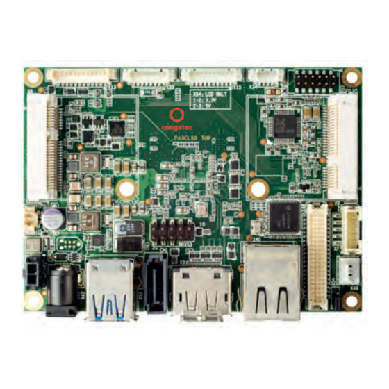
- Page 1 Pico-ITX SBC Detailed Description Of The congatec Pico-ITX Based On 3rd Generation Intel Atom User's Guide Revision 0.1 (Preliminary)
-
Page 2: Revision History
Revision History Revision Date (yyyy.mm.dd) Author Changes • 2015.10.30 Preliminary release Copyright © 2015 congatec AG PA3Cm01 2/44... -
Page 3: Intended Audience
In no event shall congatec AG be liable for any incidental, consequential, special, or exemplary damages, whether based on tort, contract or otherwise, arising out of or in connection with this user’s guide or any other information... -
Page 4: Copyright Notice
Copyright © 2015, congatec AG. All rights reserved. All text, pictures and graphics are protected by copyrights. No copying is permitted without written permission from congatec AG. congatec AG has made every attempt to ensure that the information in this document is accurate yet the information contained within is supplied “as-is”. - Page 5 (c) arising from course of performance, course of dealing, or usage of trade. congatec AG shall in no event be liable to the end user for collateral or consequential damages of any kind. congatec shall not otherwise be liable for loss, damage or expense directly or indirectly arising from the use of the product or from any other cause.
-
Page 6: Technical Support
Technical Support congatec AG technicians and engineers are committed to providing the best possible technical support for our customers so that our products can be easily used and implemented. We request that you first visit our website at www.congatec.com for the latest documentation, utilities and drivers, which have been made available to assist you. -
Page 7: Table Of Contents
Mechanical Drawing ..........41 5.6.1 Standard SATA Port ..............24 5.6.2 Mini SATA (shared with mini PCIe) ........... 24 conga-PA3 BIOS Setup Description ......... 42 Display Interfaces ..............25 5.7.1 Display Port Interface DP++ ............ 25 Additional BIOS Features ............43 5.7.2... -
Page 8: Introduction
The conga-PA3 is a Single Board Computer designed based on the Pico-ITX specification. The conga-PA3 SBC features the Intel 3rd generation Atom processors. With maximum 10W TDP processors, the SBC offers Ultra Low Power boards with high computing performance and outstanding graphics. -
Page 9: Options Information
1.2.1 Options Information The conga-PA3 is currently available in four variants (two commercial and two industrial). This user’s guide describes all of these variants. The tables below show the different configurations available. Check for the Part No. that applies to your product. This will tell you what options described in this user’s guide are available on your particular module. -
Page 10: Optional Accessories/Cables
KAB-LCD-Backlight 14000130 50cm backlight cable with JST PHR-5 connector on one end and dual connectors (JST LPCP-04 and Molex PanelMate) on the other end. Backlight cable from conga-PA3 to LCD panel (+12V LCD). USB Client Cable Adapter 14000160 30cm USB 2.0 cable with USB. 2.0 Type B connector and 1.25mm Pitch PicoBlade female connector. -
Page 11: Specification
RTC Battery congatec standard BIOS BIOS AMI Aptio ® UEFI 5.x firmware, 64MB SPI flash with congatec embedded BIOS features. Power ACPI 4.0 compliant with battery support. Also supports Suspend to RAM (S3). Ultra low standby power consumption. Management Copyright © 2015 congatec AG... -
Page 12: Supported Operating Systems
Some of the features mentioned in the above feature summary are optional. Check the article number of your module and compare it to the options information list on page 9 of this user’s guide to determine what options are available on your particular module. Supported Operating Systems The conga-PA3 supports the following operating systems. • Microsoft Windows ®... -
Page 13: Block Diagram
External I/O The mSATA/mPCIe connector supports both mPCIe and mSATA devices. The devices are detected automatically. Industrial variants are equipped with Intel i210 controller. Revision B.x and later are equipped with a multiprotocol transceiver. Copyright © 2015 congatec AG PA3Cm01 13/44... -
Page 14: Cooling Solution
Heatspreader Note You can also use a custom cooling solution for the conga-PA3. When a passive cooling is used, the end user must ensure that adequate air flow is maintained. See section 1.2.2 “Optional Accessories/Cables” for the part numbers of the cooling accessories. For the dimensions of the CSP and heatspreader, see sections 4.1 and 4.2. -
Page 15: Csp Dimension
C to 60 C. If you use heatspreaders that are not specified for the conga-PA3 or use the conga-PA3 industrial variants, then it is your responsibility to ensure that all components found on the module operate within the component manufacturer’s specified temperature range. -
Page 16: Heatspreader Dimension
DIN/IS0 specifications. Caution When using the heatspreader in a high shock and/or vibration environment, congatec recommends the use of a thread-locking fluid on the cooling solution screws to ensure the above mentioned torque specification is maintained. Copyright © 2015 congatec AG... -
Page 17: Connector Description
Connector Description Power Supply You can power the conga-PA3 SBC with a 12V, 5.5x2.5mm laptop type DC power supply (on connector X42) or with a 2 pin power supply (on connector X41). Note The supplied voltages must be within a tolerance of ± 10%. The conga-PA3 may not function if you exceed this tolerance limit. -
Page 18: Power Supply (Internal Connector)
Mating Connector: Possible mating connector for X41 is the Molex 43645-0200. Note For conga-PA3 commercial variants, you can use connector X41 as a +12V power output if the system is powered via the DC jack. The industrial variants have only connector X41 for power input. -
Page 19: Rtc Battery
For the feature connector pinout description, see section 6.1 “Feature Connectors”. RTC Battery The conga-PA3 provides an RTC battery on connector X10. The battery monitors and maintains the system clock. The specified battery type is CR2032. RTC Battery Connector X10... -
Page 20: Audio Interface
S/PDIF S/PDIF Output (3.3V) Note The audio codec is only available on commercial variants. The drivers for the codec can be found on the congatec website at www.congatec.com. Connector Type X5: 2x6 Pos, 2.0 mm Header Mating Connector: Possible mating connector for X5 is Molex 51110-1250. -
Page 21: Universal Serial Bus (Usb)
Universal Serial Bus (USB) The conga-PA3 provides 5 USB ports both on the rear side and internally. The rear side has two USB 3.0 ports on connector X52. Internally, the conga-PA3 provides two USB 2.0 ports on connector X53 and one USB client port on connector X34 . -
Page 22: Internal Usb Connectors
Internal USB Connectors The conga-PA3 offers 3 USB ports internally - two USB 2.0 ports on connector X53 and one USB client on connector X34. The signals on connector X53 are routed directly from the SoC while the signals on connector X34 are routed from the SoC via a ULPI transceiver. -
Page 23: Ethernet 10/100/1000
Ethernet 10/100/1000 The conga-PA3 provides one Gigabit Ethernet port (connector X40) on the rear side. The Gigabit Ethernet interface is supported via the Intel Gigabit Ethernet controller i211. The controller does not support the Intel AMT feature. Connectors X40 Pinout Description... -
Page 24: Sata Interfaces
5.6.1 Standard SATA Port The conga-PA3 provides one standard SATA port on connector CN1. This interface is routed directly from the SoC and supports data rates up to 3GB/s. The SATA LED signal on the feature connector X13 indicates activity on the SATA interface. -
Page 25: Display Interfaces
The conga-PA3 supports dual simultaneous displays - one Digital Display Interface and one LVDS interface. 5.7.1 Display Port Interface DP++ The conga-PA3 SBC has one DP++ connector (X3) located at the rear I/O panel. The display port supports the connection of DP, HDMI and DVI displays. Connectors X3 Pinout Description. -
Page 26: Lvds
LVDS The conga-PA3 offers LVDS interface on connector X48 - a 40 pin LVDS connector. The LVDS signals are sourced from the SoC's eDP stream via an eDP to LVDS bridge IC. The eDP to LVDS bridge processes incoming DisplayPort stream and converts the DP protocol to LVDS, before transmitting the processed stream in LVDS format. -
Page 27: Backlight Power Connector
5.7.2.2 Panel Power Selection The conga-PA3 supports 3.3V or 5V LVDS panels. With jumper X54, you can set the panel voltage (pins 35 & 37 of connector X48) to 3.3V or 5V. Copyright © 2015 congatec AG PA3Cm01... -
Page 28: Serial Ports (Com)
X54: 2mm, 3 Pos. Pin Header Serial Ports (COM) The conga-PA3 provides an RS-232 compliant UART interface on connector X16. The COM port is located at the bottom side of the SBC and can drive up to 250kb kbit/s. The conga-PA3 revision B.x and later support multi-protocol serial ports (RS232/RS422/RS485). -
Page 29: Mipi-Csi 2.0 (Camera)
MIPI-CSI 2.0 (Camera) The conga-PA3 provides a camera interface on connector X55. The interface supports up to two independent cameras - four data lanes for the first camera and one data lane for the second camera. Each lane operates at up to 1 GT/s depending on the camera resolution. It also supports up to 24 MP image capture @ 15fps, full HD 1080p60. -
Page 30: Pci Express
5.10.1 Mini PCIe (Half Size) The conga-PA3 is equipped with a PCI Express Mini Card socket. The PCIe signals are routed directly from the SoC's PCIe lane 0 to connector X8. The connector supports only mini PCIe devices. The table below lists the default pinout of the PCI Express Mini Card. - Page 31 +3.3Vaux +3.3Vaux mSATA_mPCIe_detect LED_WLAN# N.C. N.C. +1.5V N.C. N.C. +3.3Vaux Note Pin 43 of the mPCIe card must be terminated to ground for card type recognition. Connector Type X8: PCIe Mini Card Socket Copyright © 2015 congatec AG PA3Cm01 31/44...
-
Page 32: Mini Pcie (Shared With Mini Sata)
Mini PCIe (shared with mini SATA) The conga-PA3 offers a mini PCIe slot on connector X9. This connector supports both mPCIe and mSATA devices. The PCIe and SATA signals are routed from the SoC to connector X9 (mPCIe/mSATA slot) via a multiplexer. The multiplexer switches the incoming signals based on the type of card inserted. -
Page 33: Pci Express Routing
X9: PCIe Mini Card Socket Note For the conga-PA3 to detect the type of card inserted as described in the mPCIe/mSATA specification, pin 43 of the mPCIe card must be connected to ground. On mSATA card, this pin must not be connected. -
Page 34: Additional Features
LEDs, I2C, watchdog, GPIOs via these connectors. 6.1.1 Buttons & LEDs The conga-PA3 offers Lid, sleep, reset, power buttons as well as LED signals via the feature connector X13. The pinout is described below: Feature Connector X13 Pinout Description Signal Name... -
Page 35: Gpios
Signals are 3.3V compatible. The fuse limits the power budget of connector X15 and X33 by 350mA hold current. 6.1.3 I2C and Watchdog The conga-PA3 offers I2C and watchdog signals via the feature connector X33. The pinout is described below: Copyright © 2015 congatec AG PA3Cm01... -
Page 36: Congatec Board Controller (Cbc)
The conga-PA3 is equipped with a Texas Instruments Tiva™ TM4E1231H6ZRBI microcontroller. This onboard microcontroller plays an important role for most of the congatec BIOS features. The cBC fully isolates some of the embedded features such as system monitoring, I²C bus from the x86 core architecture. -
Page 37: Power Loss Control
It also keeps track of dynamically changing data like runtime meter and boot counter. 6.2.4 CPU Fan Connector The conga-PA3 supports the connection of 12V cooling fans. The signals of the CPU fan are routed to connector X49. The pinout is described below: CPU Fan Connector X49 Pinout Description... -
Page 38: Oem Default Settings
OEM POST Logo This feature allows system designers to replace the congatec POST logo displayed in the upper left corner of the screen during BIOS POST with their own BIOS POST logo. Use the congatec system utility CGUTIL 1.5.4 or later to replace/add the OEM POST logo. -
Page 39: Oem Dxe Driver
The architecture of the CGOS API driver provides the ability to write application software that runs unmodified on all congatec CPU modules. All the hardware related code is contained within the congatec embedded BIOS on the module. See section 1.1 of the CGOS API software developers guide, which is available on the congatec website . -
Page 40: Gpios
GPIOs The conga-PA3 SBC provides four GPIs and four GPOs via the congatec board controller. The GPI/GPO signals are routed to the feature connector X15. Thermal/Voltage Monitoring The CPU onboard the conga-PA3 monitors the system temperature while the congatec Board Controller monitors the +12V input voltage and input current.. -
Page 41: Conga-Pa3 Mechanical Drawing
Mechanical Drawing Copyright © 2015 congatec AG PA3Cm01 41/44... -
Page 42: Conga-Pa3 Bios Setup Description
BIOS Setup Description Copyright © 2015 congatec AG PA3Cm01 42/44... -
Page 43: Additional Bios Features
Additional BIOS Features Copyright © 2015 congatec AG PA3Cm01 43/44... -
Page 44: Industry Specifications
Industry Specifications The list below provides links to industry specifications that apply to congatec AG products. Specification Link Low Pin Count Interface Specification, Revision 1.0 (LPC) http://developer.intel.com/design/chipsets/industry/lpc.htm Universal Serial Bus (USB) Specification, Revision 2.0 http://www.usb.org/home Serial ATA Specification, Revision 3.0 http://www.serialata.org...
Need help?
Do you have a question about the conga-PA3 and is the answer not in the manual?
Questions and answers