
Related Manuals for Honeywell KMD-150


Summary of Contents for Honeywell KMD-150
- Page 1 KMD 150 Multifunction Display/GPS Pilot’s Guide 006-18220-0000 Rev 1 Mar/2000 Software Revision 1.10 or Higher...
- Page 2 ©2000 Honeywell International Inc. Reproduction of this publication or any portion thereof by any means without the express written permission of Honeywell International Inc. is prohibited. For further information contact the Manager, Technical Publications; Honeywell Business & General Aviation; One Technology Center; 23500...
-
Page 3: Table Of Contents
Table of Contents INTRODUCTION ..........1 DEFINITIONS, ACRONYMS AND ABBREVIATIONS . - Page 4 Table of Contents EDITING/CREATING A FLIGHT PLAN MANUALLY ....24 EDITING/CREATING A FLIGHT PLAN VISUALLY ....25 SELECTING A FLIGHT PLAN TO FLY .
- Page 5 Table of Contents MANUAL USER WAYPOINT EDITING ......48 GRAPHICAL USER WAYPOINT EDITING ..... . .49 EDITING USER AIRPORTS .
- Page 6 Table of Contents ALTERNATIVE MAP MODES ....... .78 Large Text Mode ........78 CDI Mode .
- Page 7 Table of Contents STORMSCOPE OPERATION ........105 INTRODUCTION .........105 FUNCTIONAL DESCRIPTION .
- Page 8 Table of Contents WEATHER DISPLAY INTERPRETATION ..... . .115 Introduction ......... .115 Radial Spread .
- Page 9 Table of Contents APPENDIX 2 - DATABASE CARDS ......135 DATA AREAS ......... . .135 CHANGING THE DATABASE CARD .
- Page 10 Table of Contents Intentionally left blank viii Rev 1 Mar/2000 KMD 150 Pilot's Guide...
- Page 11 Table of Contents SCREEN INDEX Screen 1: Title Screen ........33 Screen 2: Main Menu Screen .
- Page 12 Table of Contents Screen 25: PIN Incorrect Screen .......94 Screen 26: PIN Change & Power-On Lock Enable Screen ... .95 Screen 27: PIN Change Screen .
- Page 13 Table of Contents Screen 48: NAV Information and WTP IMMINENT Flags Showing - Enroute Screen ........76 Screen 49: NAV Information and TP IMMINENT Flags Showing - Final Screen .
- Page 14 Table of Contents Intentionally left blank Rev 1 Mar/2000 KMD 150 Pilot's Guide...
-
Page 15: Introduction
Introduction INTRODUCTION All of us at Honeywell congratulate you on choosing this product. You are now the owner of one of the most sophisticated yet simple-to-use Navaids available today. We understand you probably can’t wait to see it in action but before you try to use it do please take the time to read through this manual and understand its many interesting and useful fea- tures. -
Page 16: Definitions, Acronyms And Abbreviations
Introduction The altitude calculated by GPS equipment is geometric height above a theoretical mean sea level of a mathematically calculated ellipsoid that approximates to the shape of the earth. This altitude can differ signifi- cantly from that displayed by your pressure altimeter. You must there- fore, NEVER USE GPS ALTITUDE FOR VERTICAL NAVIGATION OR TERRAIN AVOIDANCE. - Page 17 Introduction Data List: an ordered list of data elements which a given cursor field can accept Desired Track: The angle that the desired flight path makes with respect to true north at the point nearest the present position. Magnetic desired track uses the local magnetic variation. Destination: If the active user waypoint is not in the active flight plan, the active user waypoint is the destination.
-
Page 18: Acronyms And Abbreviations
Introduction Standard Rate Turn: 3°/sec Tailwind: difference between ground speed and true airspeed when ground speed is more than true airspeed Terminal User Waypoints: user waypoints that are duplicated within a country code or “unnamed” user waypoints associated with an approach that are assigned to distinct airports Time To User Waypoint: distance to user waypoint divided by ground speed... - Page 19 Introduction CTA: Control Area CTAF: Common Traffic Advisory Frequency CTR: Control Zone CTZ: Control Tower Zone CWI: Continuous Wave Interference decibels Direct Current DIS: Distance DME: Distance Measuring Equipment DOT: United States Department of Transportation EFIS: Electronic Flight Instrument System ELT: Emergency Locator Transmitter ESA:...
- Page 20 Introduction IEEE: Institute of Electrical and Electronics Engineering IFR: Instrument Flight Rules in.: inches INT: Intersection kHz: kilohertz Kt.: Knots KΩ: Kilohms LAT: Latitude Pounds LED: Light Emitting Diode LON: Longitude LONG: Longitude LRU: Line Replaceable Unit meters milliamperes MATZ: Military Air Traffic Zone MAHP: Missed Approach Holding Point...
- Page 21 Introduction NVM: Non Volatile Memory OBI: Omni-directional Bearing Indicator OBS: Omni-directional Bearing Selector PETE: Pointer ETE PIN: Personal Identification Number RAD: Radial REF: Reference RMI: Radio Magnetic Indicator RTCA: Radio Technical Commission for Aeronautics Selective Availability (intentional errors introduced by the DOD) SAT: Static Air Temperature sec:...
- Page 22 Introduction Watts wpt: Waypoint µsec: microsecond µV: microvolts Ω: Ohms °C: degrees Celsius °F: degrees Fahrenheit Rev 1 Mar/2000 KMD 150 Pilot's Guide...
-
Page 23: General Information
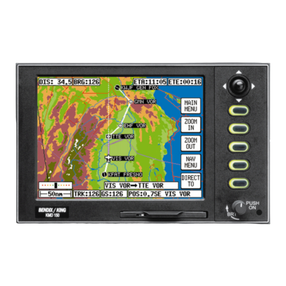
General Information GENERAL INFORMATION This section of the manual explains how it should be used and provides you with an overview of the software architecture and screen presenta- tion of your KMD 150 Multifunction Display/GPS. This manual provides a detailed explanation of each of the individual screens that your KMD 150 unit displays, and will take you step by step through each of them. -
Page 24: Soft Keying
General Information SOFT KEYING You will notice that a label is drawn alongside each valid key. Whenever a new function is selected, by pressing a valid key, a new screen is dis- played along with its new key labels. This capability of drawing key labels that are only applicable to a particular screen is referred to as ‘soft keying’, and allows one key to perform multiple functions without the complications of multiple key presses on a conventional keypad. -
Page 25: Stormscope Option
General Information STORMSCOPE OPTION The KMD 150 has the ability to interface and control a BFGoodrich WX- 500 Stormscope ‘black box’ thunder storm sensor. The Stormscope interface is switched on and off by using the joystick while displaying the Main Menu screen. When the Stormscope interface is selected on, Key 1 on the main menu screen gives access to a dedicated Stormscope screen. - Page 26 General Information GPS STATUS If using the internal GPS, this shows satellite signal strength, allows UTC, local offset, date and position to be set, which will speed up the initialization of your unit. DATA I/O If using an external GPS, this shows the data input/output settings and status.
- Page 27 General Information PIN SETUP Allows the PIN security function to be Setup. INST & DIAGS Allows installation and diagnostics for data input/output and GPS receiver (KMD 150 only) to be performed. Flight logs can be viewed and various sections of memory can be cleared from here. This is the primary operating mode of the unit.
-
Page 28: Screen Icons
General Information SCREEN ICONS When showing any map screen - airports, navaids, towns, intersections, user waypoints and many other data classes are represented by sym- bols or icons, some of which are user selectable in the Map Setup Screens. Please refer to the Setup Screens Section of this manual for further details. -
Page 29: Memory Locations
General Information NOTE: Terrain data is not available for certain areas of SOUTH AMERICA cen- tering on the Amazon Basin and in EUROPE a larger portion of the Ukraine bordering Russia. Please exercise extreme caution when flying in these areas because all terrain is displayed as less than 1000 feet/500 feet respectively, on the KMD 150. - Page 30 General Information Intentionally left blank Rev 1 Mar/2000 KMD 150 Pilot's Guide...
-
Page 31: Getting Started
Getting Started GETTING STARTED This section of the manual is designed to provide you with a quick refer- ence guide into the operation of your Bendix/King KMD 150 unit; taking you step by step through the most common functions. If more detail is required, please refer to the appropriate sections in this manual. -
Page 32: Software Structure
Getting Started Altering UTC & DATE: Select UTC & DATE, fol- lowed by ADJUST UTC. Use the joystick to adjust the time, then press SET. Now select ADJUST DATE and use the joy- stick to adjust the date, and then press SET fol- lowed by GPS STATUS. -
Page 33: Selecting Demo Mode
Getting Started SET UP: Allows Setup of map, NAV, PIN and input/output characteris- tics. MAP: This is the primary mode of the unit. Stormscope mode is switched on and off on this screen using the joy- stick. As a rule, when trying to get to a specific function in another branch of software you should work your way back up the present branch to MAIN MENU by pressing the PREV PAGE or MAIN MENU keys. -
Page 34: Database Selection
Getting Started DATABASE SELECTION Both the internal way- points (i.e. Jeppesen data, cities etc.) and user defined waypoints are stored in your unit in a series of databases. During normal use of your unit you will need to select items from these databases, whether it is to find out airport fre- quency information, or... -
Page 35: Visual Direct To And Data Interrogation
Getting Started flight plan will be put to sleep and the displayed navigation data in MAP mode will be to the DIRECT TO point. You will always know when a DIRECT TO is running because the DIRECT TO key will be labeled DIRECT TO OFF. -
Page 36: Manual Direct To And Data Interrogation
Getting Started joystick to dial in the required latitude and longitude, followed by ENTER. The unit will then provide you with full navigation information to reach this Temporary Waypoint point. This function is not available in External GPS Mode. MANUAL DIRECT TO AND DATA INTERROGATION Provided the pointer is not active in MAP mode, press the DIRECT TO... -
Page 37: Editing/Creating A User Waypoint Visually
Getting Started EDITING/CREATING A USER WAYPOINT VISUALLY From MAIN MENU select the FLIGHT PLAN key, followed by USER WPTS. You may then use the joystick to select a specific user waypoint (either by number or name). Press the VIEW MAP key and the adja- cent screen will be shown with previously... -
Page 38: Selecting Stormscope Mode
Getting Started SELECTING STORMSCOPE MODE Stormscope installed the display screen can be selected from the MAIN MENU. When lightning detected, the KMD150 will annunciate LIGHT- NING in the MAP mode, to see details of the strike select MAIN MENU and STORM SCOPE to call the strike screen ranged at 200nm. -
Page 39: Editing/Creating A Flight Plan Visually
Getting Started EDITING/CREATING A FLIGHT PLAN VISUALLY From MAIN MENU select the FLIGHT PLAN key, followed by EDIT FPLN. Use the joystick to select the desired flight plan number and then press VIEW MAP. If the selected flight plan was empty, the adjacent screen will... -
Page 40: Selecting A Flight Plan To Fly
Getting Started SELECTING A FLIGHT PLAN TO FLY From MAIN MENU select the MAP key, followed by NAV MENU and FLIGHT PLAN. Use the joystick to select the desired flight plan number and then press the SELECT key. Ensure that the leg arrow is pointing at the initial leg that is to be flown and press FLY FPLN. -
Page 41: Viewing Etas, Direct-To On Flight Plan
Getting Started VIEWING ETAS, DIRECT-TO ON FLIGHT PLAN When a flight plan is run- ning the ETA to each point in that flight plan viewed pressing the DIRECT TO key on the map. entry to the adjacent screen the cursor high- lights the waypoint in MAGENTA that is cur- rently being navigated to. -
Page 42: Setup Map Functions
Getting Started SETUP MAP FUNCTIONS These screens allow the mapping functions to be configured. The initial screen is reached by pressing SET UP in MAIN MENU, followed by MAP SETUP. The sub- sequent screens are reached by pressing the NEXT key. On the initial page each of the displayed features can be set by using the... - Page 43 Getting Started SURFACE REQUIRED: Sets min- imum runway surface required for ten nearest airports. EXT TRACK: Turns on or off the extended track line, which is drawn ahead of your present position in the direction of your present track. AUTO ZOOM: Turns on or off.
-
Page 44: Setup Of Navigation Functions
Getting Started SETUP OF NAVIGATION FUNCTIONS The adjacent screen allows the navigation functions to be config- ured. It can be reached by pressing SET UP in MAIN MENU, followed by NAV SETUP. This screen is not available in External GPS mode. Each of the displayed features can be set by using the joystick. -
Page 45: Clear Memory
Getting Started Any changes made in this screen will be saved once the OK key has been pressed. At any time the RESET VALUES key can be pressed to return your unit to the default settings. If you wish to reset all setup options (including MAP SETUP options) to their default setting press the CLEAR SETUP key in the Clear Memory screen. - Page 46 Getting Started Intentionally left blank Rev 1 Mar/2000 KMD 150 Pilot's Guide...
-
Page 47: Title And Help Screens
Title and Help Screens TITLE AND HELP SCREENS To switch the unit on, push the On/Off/Brightness control in then rotate fully clockwise. Your unit produces a variety of tones and alarms to assist you in correct operation. At this stage only two types of tone need concern you. These are: 1 short beep sounds when you press a valid key. -
Page 48: Self Test And Initialization
Title and Help Screens SELF TEST AND INITIALIZATION When the Title Screen is initially displayed, no key labels are drawn while a series of internal check routines are carried out automatically by the unit. These are: 1. Verification that the unit has been factory initialized. This consists of a check to see if there is a special code in NVM. -
Page 49: Main Menu Screen
Title and Help Screens MAIN MENU SCREEN If set up for internal GPS use, Key 1 calls Screen which is the GPS Status Screen. The joy- stick can be used on this screen to switch the BFGoodrich WX-500 Stormscope interface on and off. - Page 50 DUATS, special instruction for an unfamiliar destination etc. Using the 'Flight Manager' software from Honeywell you can prepare and store a library of Note Pad files and load the relevant one into your KMD 150 unit to suit your day's flying.
-
Page 51: Gps Status Screens
GPS Status Screens GPS STATUS SCREENS This Screen is only accessible if Internal GPS source is selected and is accessed by pressing Key 1,GPS STATUS, in Main Menu. The GPS Status Screen will display the receiver STATUS. This can be any of the following: Screen 3: GPS Status Screen BAD ALMANAC... - Page 52 GPS Status Screens POS PROP means that navigation has been temporarily lost and the KMD 150 is dead-reckoning (or propagating) its position based on the last known position, track and ground speed. It will not dead-reckon for more than a few seconds at a time. Other information that is displayed, on this Screen includes: ANTENNA CURRENT Against this heading there will be an indication if the antenna is drawing too much, too little or the correct amount of cur-...
- Page 53 GPS Status Screens CA: Code Acquire. This means the satellite code has been received and matched to the receiver-generated code. AS: AGC Set. This means the satellite strength has been assessed and the Automatic Gain Control has been set. FA: Frequency Acquire. This means the receiver has correctly locked onto the satellite data frequency.
-
Page 54: Adjusting Time And Date
GPS Status Screens ADJUSTING TIME AND DATE Pressing GPS STATUS in Main Menu followed by UTC & DATE accesses this Screen. Pressing Key 3, ADJUST UTC, places a cursor over the first digit of the Hours value on the time display. The value can then be increased or decreased by moving the joystick up or down. -
Page 55: Setting Present Position
GPS Status Screens of two values, 00 or 30. Only after pressing Key 1 SET is the information saved and the display reverts to Screen 3, GPS Status Screen. The local offset is held in RAM and added to UTC time when calculating ETA's. - Page 56 GPS Status Screens If the unit is receiving sufficient satellite signals to calculate a fix, user- entered latitude and longitude will be ignored. Keys 3 and 4 give direct access to Time and Date adjustment. Rev 1 Mar/2000 KMD 150 Pilot's Guide...
-
Page 57: Data Input (External Gps Mode)
Data Input DATA INPUT (EXTERNAL GPS MODE) If you own the non-GPS version of KMD 150, or as an alternative to using the internal GPS receiver, your KMD 150 has been wired to accept data from a remote GPS or LORAN unit, you will be operating in External GPS Mode and this section applies to you. -
Page 58: Nmea And Northstar Data
Data Input Important Note for Garmin GPS Users Although Garmin products output the Bendix/King equivalent ARNAV R- 30 (RS232) data sentence format, when put into OBS Mode some Garmin GPS units stop sending all data including GPS position. In these circumstances your KMD 150 will display an error message saying NO EXTERNAL GPS DATA since it is not receiving present position. -
Page 59: Flight Planning Screens
Flight Planning Screens FLIGHT PLANNING SCREENS These screens are not available in External GPS Mode (see section 6 for details of flight plans in External GPS mode). In order to allow you to navigate along pre-planned Flight Plans, your KMD 150 has facilities to memorize up to 500 user waypoints. -
Page 60: User Defined Airports
Flight Planning Screens this user waypoint is to be used as a marker point only and that no name is to be printed next to the user waypoint icon on the map. The X.X spec- ifies the alarm trigger distance between 0.1nm and 9.9nm. The default is 1.0nm. -
Page 61: Viewing User Waypoints
Flight Planning Screens Pressing Key 2, FLIGHT PLAN, in Main Menu, accesses this Screen. Key 1 returns to Main Menu. Key 2, EDIT FPLN, gives access to flight plan cre- ation and editing pages. Key 3, USER WPTS, gives access to user way- point creation and editing Screen 7: Flight Planning Mode Cover pages. -
Page 62: Manual User Waypoint Editing
Flight Planning Screens words [FPLN LINK] will be printed next to the user waypoint number. It is necessary to think carefully before editing any user waypoint marked FPLN LINK since any changes you make to the user waypoint are liable also to affect one or more of the programmed flight plans. -
Page 63: Graphical User Waypoint Editing
Flight Planning Screens When the cursor is moved to the right after the last character in a line, the POS field will be updated and the cursor will move to the next line heading. i.e. from the last character in the name, the cursor will go to the word LAT and similarly from the last digit of the longitude it will go to the word ICON. -
Page 64: Editing User Airports
Flight Planning Screens New user waypoints can be created wherever the pointer is placed simply by pressing Key 2, ENTER WPT. Existing user waypoints can be deleted by positioning the pointer directly over them and then pressing Key 5, DELETE WPT. Should you attempt to delete a user waypoint that is being used in a stored Flight Plan, the [PRESENT IN FLIGHT PLAN] message box will be displayed and the user waypoint will NOT be deleted. -
Page 65: Manual Flight Plan Building And Editing
Flight Planning Screens database (which is subdivided and arranged alphabetically) and also, if you wish, from your own list of user waypoints. Pressing FLIGHT PLAN in Main Menu, followed by EDIT FPLN, accesses this Screen. As you enter this Screen you will find a cursor positioned over the flight plan number. - Page 66 Flight Planning Screens When you enter this Screen you will find a cursor positioned over the first item in the chosen flight plan. By using the joystick, you can move the cursor up or down. This enables you to scroll in either direction through the entire flight plan in the display box.
-
Page 67: Manually Inserting A Waypoint Into A Flight Plan And Manual Direct To
Flight Planning Screens MANUALLY INSERTING A WAYPOINT INTO A FLIGHT PLAN AND MANUAL DIRECT TO A Waypoint can be inserted into a flight plan by using a two step process that is started by pressing Key 2 INSERT ITEM. The same process is followed when Key 5 DIRECT TO is selected in Screen 38, Map Mode... -
Page 68: Selecting Item From Chosen Database
Flight Planning Screens If Key 1, PREV PAGE, is pressed to discontinue the selection process the unit will return to whichever the previous Screen was, either Screen Flight Plan Program/Edit Screen, or Screen 38, Map Mode. This Screen allows you to select a DIRECT TO spe- cific latitude and longi- tude, and is reached by... - Page 69 Flight Planning Screens If AIRPORTS was selected on Screen 13 the cursor will be positioned over the word ICAO:. Airports may be selected by ICAO code, airport name or associated city name and in addition, once an airport has been selected, a particular runway threshold at that airport can be selected.
-
Page 70: Graphical Viewing And Editing Of Flight Plans
Flight Planning Screens NOTE: When selecting a navaid, intersection or approach waypoint, check the ICAO area code carefully since there are many duplicates present in the database. Checking the area code will eliminate any ambiguity. GRAPHICAL VIEWING AND EDITING OF FLIGHT PLANS This Screen is accessed by pressing FLIGHT PLAN in Main Menu, fol-... - Page 71 Flight Planning Screens wish to add a new waypoint). As soon as you do this, the ADD WPT or GRAB LINE key will appear. Press the ADD WPT or GRAB LINE key to join the pointer back to the flight plan line and then move it to the new waypoint.
- Page 72 Flight Planning Screens Intentionally left blank Rev 1 Mar/2000 KMD 150 Pilot's Guide...
-
Page 73: Map Mode Screens
Map Mode Screens MAP MODE SCREENS Pressing MAP in Main Menu accesses this Screen. When you enter this Screen, if the KMD 150's internal receiver has been able to establish a fix or if the external GPS you are using to feed your unit is sending valid data, a Screen similar to the one shown here will be dis-... - Page 74 Map Mode Screens The box marked POS: will display your present position as a distance and cardinal bearing from the nearest item in the database. The geo- graphical item used to describe your position to you is chosen on the basis of the POSITION REF: setting on Screen 22, Map Customization...
-
Page 75: Data Interrogation And Graphical Direct To
Map Mode Screens DATA INTERROGATION AND GRAPHICAL DIRECT TO As soon as you move the joystick while in Screen Map Mode, a Screen similar to Screen 39 will be displayed. The map freezes in its present posi- tion with respect to the joystick pointer and the aircraft symbol indicating your present position... -
Page 76: Airport Information
Map Mode Screens AIRPORT INFORMATION As explained previously, you can access this Screen from Screen 39 by placing the joystick pointer over an airport icon and pressing Key 4, MORE INFO. All the information given here is derived from the built-in Jeppesen database. -
Page 77: General Icon Information
Map Mode Screens do is press Key 2, IDENT. The unit will beep out the correct ident (on its internal speaker and on the external alarm, if this is switched on). You can then compare this to the ident you are hearing over the radio to verify that you are indeed tuned to the navaid you want. -
Page 78: Screen 40B: Airspace Information Screen
Map Mode Screens IMPORTANT: When a single airspace boundary line is shared by two different pieces of airspace (which is very common), the airspace with the lower vertical limit will always be highlighted. Once you are sure the piece of airspace highlighted is the piece you want information on (you may have to zoom out to verify this, but beware, some airspace switches off as you zoom out dependant on the settings made in... -
Page 79: Nav Menu Screens
Nav Menu Screens NAV MENU SCREENS You can enter this impor- tant Screen by pressing Key 4, NAV MENU (or MAP MENU if set to External GPS), while in Map Mode (on Screen 38 47). It is a versatile Screen with several useful functions. - Page 80 Nav Menu Screens Please refer to the Map Setup Screens in the Setup Screens Section of this manual for further information regarding data settings for each mode. If you wish to return to the Map Screen at any time, press Key 1, MAP. Key 2, FLIGHT PLAN, gives you direct access to Flight Planning Mode where you can manually select, cancel and edit Flight Plans as required.
-
Page 81: Selecting A Flight Plan
Nav Menu Screens SELECTING A FLIGHT PLAN Pressing Key 2, FLIGHT PLAN, on Screen 41, Menu Cover Screen, enters this Screen. On entry to this Screen you will see a cursor positioned over the Number of the last flight plan accessed, or if there is a flight plan already active,... -
Page 82: Ten Nearest Airports
Nav Menu Screens In order to select a flight plan to fly, bring up the desired Flight Plan Number with the joystick press SELECT, in Screen 42, Flight Plan Selection Screen. This will call Screen 12 from which you can choose to edit the flight plan, reverse the flight plan or activate the flight plan. -
Page 83: Screen 44: Airport Information Screen
Nav Menu Screens To obtain a DIRECT TO for the chosen airport all you have to do is press Key 5, labeled DIRECT TO, and you will switch back to (Screen Map Mode with the selected DIRECT TO activated. Key 1, MAP, returns you to Map Mode ,Screen 38 Key 2 returns you to the NAV Menu Cover Screen... -
Page 84: Navaids
Nav Menu Screens NAVAIDS This Screen is accessed by pressing Key 4, NEAR NAVAID, Screen 41, NAV Menu Cover Screen, dynamically shows the range and bearing of the ten nearest navaids. When this Screen appears you will find a cursor placed over the first navaid in the list. - Page 85 Nav Menu Screens If you want to view the area immediately around the chosen navaid, press Key 4. This will call Screen 10A that is very similar to screen 10, the View and Edit User Waypoint on the Map Screen. Screen 10A will revert back to...
- Page 86 Nav Menu Screens Intentionally left blank Rev 1 Mar/2000 KMD 150 Pilot's Guide...
-
Page 87: Map Mode With Nav Information
Map Mode with Nav Information MAP MODE WITH NAV INFORMATION This section applies to Internal GPS mode only. Whenever a Flight Plan is active or you have called for a DIRECT TO, the map will have extra navi- gation information added to it and will resemble Screen 47. - Page 88 Map Mode with Nav Information lowing relates to when the screen is in Landscape Mode. The position of some of the items is different when Portrait Mode is used.) Starting at the top of the screen on the left hand side you will see DIS. This is the dis- tance or range to run to the destination point from your present position.
-
Page 89: Viewing Enroute Eta's, Performing A Direct-To On Top Of Flight Plan
Map Mode with Nav Information VIEWING ENROUTE ETA'S, PERFORMING A DIRECT-TO ON TOP OF FLIGHT PLAN When flying a flight plan, the ETA's for each leg of the flight plan can be viewed on Screen 41A which is accessed by pressing Key 5 (DIRECT TO) on the MAP screen (screen 41) -
Page 90: Arrival At An Enroute User Waypoint
Map Mode with Nav Information ARRIVAL AT AN ENROUTE USER WAYPOINT To set the radius for the Arrival Alarm you should refer to the data on Screen 23, NAV Mode Customization Screen. When distance remaining to run to an enroute user waypoint falls below the Arrival Alarm value, the [WPT ALERT] flag is displayed... -
Page 91: Arrival At Your Final Destination
Map Mode with Nav Information and less than 90°. If the course change is less than 5° then turn antici- pation is not necessary. If the course change is greater than 90° it is up to the pilot which way round the waypoint he turns. If Turn Anticipation is set to ON and the upcoming leg satisfies the Turn Anticipation rules (i.e. -
Page 92: Alternative Map Modes
Map Mode with Nav Information ALTERNATIVE MAP MODES You may have selected one of the other Map Modes detailed in the Menu Screens Section of this manual. The same navigation data as described previously is presented on all the alternative screens in dif- ferent ways. - Page 93 Map Mode with Nav Information waypoint (i.e. magnetic bearing to waypoint if you were on track). On entering NAV Mode or activating a new flight plan leg or a DIRECT TO, the outer ring will show the desired track to the active waypoint. A GPS TRACK bug that rotates with the aircraft's actual track, is posi- tioned on the CDI outer ring.
- Page 94 Map Mode with Nav Information turning left it would then be possible to intercept the new track line then fly straight into the airport on the new approach heading. If the joystick is touched, the display will immediately revert to Large Map format to allow full use of map graphics.
-
Page 95: E6-B Calculator
E6-B Calculator E6-B CALCULATOR E6-B functions are acces- sible by pressing Key 3, NOTE PAD, in Main Menu followed by Key 3, E6-B CALC, in the Note Pad Screen. This gives access to Screen 57, E6- B Calculator Screen. This function is not avail- able in Demo Mode. -
Page 96: To Calculate Winds Aloft (Wind) And Headwind/Tailwind
E6-B Calculator 3. Move the cursor over the entry field next to the heading PRESS and enter the atmospheric pressure in either inches of mercury (Hg) or mil- libars (mb). Default value is 29.92Hg / 1013mb. 4. Move the cursor over the entry field next to the heading TAT and enter the total air temperature read from your external aircraft ther- mometer in either F or C. -
Page 97: Screen 59: Vnav Setup Screen
E6-B Calculator On entry to Screen 59, if there is no active user waypoint the DESTINA- TION box will read NO WAYPOINT. You must have an active user way- point in order to activate VNAV Mode. If there is an active user waypoint the destination user way- point name will be shown. -
Page 98: Trip/Fuel Planning
E6-B Calculator 1. Key 5 will now read VNAV OFF and there is a new VNAV message box. 2. If the DESCEND IN counter is greater than 00:00, the new message box will show DESCEND IN with the counter value. 3. -
Page 99: Screen 60: Trip / Fuel Flight Plan Select Screen
E6-B Calculator All you need to input is your cruising speed and your fuel burn. Fuel burn is entered in units / hour. The units are not important. If you fill your aircraft tanks using US gallons, enter your fuel flow in US gallons / hour. -
Page 100: Sunset/Sunrise Calculator
E6-B Calculator SUNSET/SUNRISE CALCULATOR This feature is entered by pressing SUNSET/RISE, Screen E6-B Calculator Cover Screen, and allows you to calcu- late sunrise and sunset times for any point in the world. You will be asked to input a latitude, longi- tude and date. -
Page 101: Setup Screens
Setup Screens SETUP SCREENS Your KMD 150 unit allows you a great deal of flexibility to customize it to suit your own wishes and requirements. It also contains a high level of automatic self-testing and diagnostics. All cus- tomization and diagnostic functions are grouped together in this Setup section. -
Page 102: Settings Available
Setup Screens headings. When the cursor is over the heading you wish to alter, move the joystick to the right. This will in turn move the cursor over to the set of options available for that heading. Moving the joystick up and down will then allow you to scroll through these options. - Page 103 Setup Screens kilometers are selected, all lengths and altitudes will be reported in meters. COORD SYSTEM: This option controls whether the unit operates with reference to Latitude/Longitude or UTM or OSGB grid references. LANGUAGE: This is self-explanatory; it enables you to choose the lan- guage in which you would prefer the unit to operate.
-
Page 104: Screen 22A: Point Features Data Class Setup Screen
Setup Screens lower priority icon label will be removed. This prevents icon label over- laps and clashes and hence declutters the map. KEY BEEP: This allows you to select the beep that occurs when you press a key or move the joystick on or off. LOGGING RATE: This gives you the choice of how often your position is stored in memory for playback in Demo Mode or to a PC. -
Page 105: Screen 22B: Line Features Data Class Setup Screen
Not all data classes shown in the illustrations are available for all geo- graphic areas. Details of the data classes available on the database card you have installed are available from Honeywell. Please think carefully before altering any of the settings on these screens. -
Page 106: Nav Mode Setup
Setup Screens NAV MODE SETUP This screen is not avail- able in External GPS mode. When you first enter this Screen the cur- rent settings are dis- played with a cursor over the words CDI SCALE. You then have to use the joystick to move the cursor up or down. - Page 107 Setup Screens be switched off. If selected OFF, the CDI is no longer shown while you are in Map Mode. CDI ALARM: When selected ON this produces an audible alarm to tell you when full-scale deflection of the CDI has been reached. If you choose to set this to OFF, you disable this alarm.
-
Page 108: Personal Identification Number (Pin) Setup
Setup Screens PERSONAL IDENTIFICATION NUMBER (PIN) SETUP We have provided the security feature of a Personal Identification Number (PIN) in your KMD 150 unit with the main aim of preventing unauthorized persons from using your naviga- tion equipment. You may use this Screen to set up your own choice of a four-digit... -
Page 109: Screen 26: Pin Change & Power-On Lock Enable Screen
Setup Screens If you have managed to get the PIN correct then you move straight to Screen 26 as illustrated previously. On entry to this Screen, the current PIN is displayed and the status of the AUTO POWER-ON LOCK is displayed. -
Page 110: Auto Power-On Lock
Ltd. if in the United Kingdom). You will require the Serial Number of your unit and the Lock-Out Number, which you can read from the top of Screen 55. The operator at your dealer or at Honeywell will verify these details and check them against the Honeywell database and register of stolen units. -
Page 111: Installation And Diagnostic Screens
Setup Screens INSTALLATION AND DIAGNOSTIC SCREENS This Screen is accessed by pressing Key 4, SETUP, in Main Menu followed by Key 5, INST & DIAGS, in Screen 21, Setup Cover Screen. Screen 28 gives you access to all installation and test-related Screens, and will allow you to per- form diagnostic checks on the data input and... -
Page 112: View Logs
(It is perhaps worth noting that a copy of the cumulative total of hours run remains recorded within the NVM, cannot be user-reset and can only be read by Honeywell technicians.) The Total Flight Hours is a value stored in exactly the same way as Total... -
Page 113: Clear Memory
Setup Screens 2D or 3D fix. You can if you wish also reset these figures along with the Total Unit Hours Run value by using Screen 33, Memory Clear Screen. CLEAR MEMORY All the routines, which can clear the unit's memory, are protected by your PIN specifically to prevent any unauthorized... -
Page 114: Data In/Out
Setup Screens If you press Key 3, labeled "CLEAR WPTS", a similar procedure will be followed, and pressing, "YES" will this time clear all User waypoints from memory including those being used in Flight Plans. Use of Key 4, labeled "CLEAR SETUP", will reset all the User-Defined Options within the unit to their original default values. -
Page 115: External Gps Data Input Option
Setup Screens information on these screens is required please refer to the KMD 150 Installation Manual for all Stormscope diagnostic related functions. If you do not have a Stormscope connected, ensure this option is switched off. Below STORM- SCOPE setting is the GPS SOURCE setting. -
Page 116: Output Test
Setup Screens Once the physical connection to the host GPS or LORAN has been made, it is essential to select an appropriate data output on the host unit. This can be done by referring to the manual for the host GPS/LORAN and choosing an option that corresponds to one of the compatible data input types listed previously. - Page 117 Setup Screens CDI FLAG In View Ensure CDI or NAV flag is visible Out of View Ensure CDI or NAV flag is not visible TO/FROM FLAG Ensure TO flag is visible FROM Ensure FROM flag is visible FLAG OUT OF VIEW Ensure TO and FROM are not visible NAV SUPERFLAG ACTIVE Ensure Nav Superflag is active...
- Page 118 Setup Screens Intentionally left blank Rev 1 Mar/2000 KMD 150 Pilot's Guide...
-
Page 119: Stormscope Operation
Stormscope Operation STORMSCOPE OPERATION INTRODUCTION Your Bendix/King KMD 150 is capable of being interfaced to a BFGoodrich WX-500 Stormscope Series II Weather Mapping Sensor. The WX-500 detects electrical discharges associated with thunderstorms within a 200 nm radius of the aircraft. The information is then sent to your KMD 150 that will display the location of the thunderstorms both on the map screens and on a dedicated Stormscope screen. -
Page 120: Cell Display Mode
Stormscope Operation CELL DISPLAY MODE When viewing the dedicated Stormscope screen, if cell display mode is selected, the KMD 150 plots a "+" symbol (discharge point) on the dis- play when it detects associated discharges within the selected range and view. -
Page 121: Anatomy Of A Thunderstorm
Stormscope Operation • Discharge rate indicator-displays estimated average discharge rate per minute for current range and view • Mic inhibit - inhibits thunderstorm processing when the communications transmitter is keyed to prevent the processing of corrupted data (some aircraft need to use this feature, others don’t). ANATOMY OF A THUNDERSTORM The Stormscope model WX-500 is intended to help pilots avoid the dan- gers associated with thunderstorms (convective wind shear, lightning,... -
Page 122: Stages Of A Thunderstorm
Stormscope Operation d) All electrical discharges radiate electromagnetic signals in all direc- tions at the speed of light. The electromagnetic signals have unique characteristics and varying rates of recurrence and signal strength. Figure 13-3 shows that the rate of electrical discharges detected in an area is directly related to the amount of convective wind shear turbu- lence present. -
Page 123: Mature Stage
Stormscope Operation Mature Stage In the mature and most intense stage of a thunderstorm, the water droplets within the cloud collide and combine to form rain and hail and, at cooler temperatures, sleet and snow. This stage poses many hazards to aircraft including heavy precipitation, high winds, convective wind shear, severe turbulence, downbursts, hail, icing, tornadoes, and lightning. -
Page 124: Operation
Stormscope Operation OPERATION As mentioned earlier, the WX-500 is controlled through the KMD 150. The focus on this section is to provide both background information and a more detailed explanation of the operating procedures. The following text assumes you have both the WX-500 and the KMD 150 switched on and that you have selected the Stormscope screen from the main menu on the KMD 150. -
Page 125: Clear All Discharge Points
Stormscope Operation CLEAR ALL DISCHARGE POINTS Clearing the discharge points periodically while you are monitoring thun- derstorms is a good way to determine if the storm is building or dissi- pating. Discharge points in a building storm will reappear faster and in larger numbers. -
Page 126: Operation In Stormscope Mode With Nav Overlay
Stormscope Operation OPERATION IN STORMSCOPE MODE WITH NAV OVERLAY If you are running a Flight Plan or have performed a DIRECT TO, the Flight Plan lines and waypoints will be displayed on the Stormscope screens in the form of an overlay. NOTE: In order to align the lightning strikes correctly to the flight plan lines, heading information is necessary. -
Page 127: Error Messages
Stormscope Operation ERROR MESSAGES The WX-500 detects most common faults and sends error messages to the KMD 150 indicating the nature of the faults and which functions may be inoperative. These error messages enable your authorized Stormscope dealer or BFG Avionics Systems factory service personnel to quickly diagnose and correct the fault. -
Page 128: Non-Fatal Faults
Stormscope Operation If the KMD 150 receives an error message, an ERROR warning mes- sage will be displayed at the top of the Stormscope screen followed by an error number. If you receive one of these error warnings, make a note of the error number and report it to your authorized Stormscope dealer as soon as possible. -
Page 129: Weather Display Interpretation
Stormscope Operation WEATHER DISPLAY INTERPRETATION WARNING The illustrations in this guide are only examples. Never use your WX-500 to attempt to penetrate a thunderstorm. The FAA Advisory Circular, Subject: Thunderstorms, and the Airman's Information Manual (AIM) recommend that you "avoid by at least 20 miles any thunderstorm identified as severe or giving an intense radar echo."... -
Page 130: Radial Spread
Stormscope Operation The WX-500 detects electrical discharges and sends them to the KMD 150 as storm cells or as independent strikes. The following examples include the KMD 150's Stormscope screens in both the cell display mode and the strike display mode. When in map mode, if enabled, the cells and strikes will be displayed as lightning icons. - Page 131 Stormscope Operation The Stormscope screen can also tell us about the relative amount of electrical discharge activity in thunderstorm cells. Clusters 2 and 3 have more discharge points than cluster 1 indicating greater electrical dis- charge activity. All three clusters however must be avoided because you can't necessarily determine the severity of thunderstorms based strictly on the number of discharge points.
- Page 132 Stormscope Operation When the Stormscope range is changed to 100 nm (Figure 13-6), only cluster 2 remains visible. Clusters 1 and 3 are beyond the 100 nm range and therefore no longer appear on the screen. (Clusters 1 and 3 would again be visible if the range were returned to 200 nm.) Cluster 2 is now more defined and the discharge points are larger.
-
Page 133: Two Clusters Within The 200Nm Range Ring
Stormscope Operation Two Clusters within the 200 nm Range Ring Figure 13-7 shows the Stormscope screen in the 360° weather view at the 200 nm range. Using this knowledge, the outer range ring, and the azimuth markers, the two clusters of discharge points on the Stormscope screen can be interpreted as representing one thunderstorm cell at 5:30, about 150 nm from the aircraft, and another thunderstorm cell at 1:00, about 100 nm from the aircraft. -
Page 134: Mapping Headings Past Thunderstorms
Stormscope Operation MAPPING HEADINGS PAST THUNDERSTORMS Figures 13-8 through 13-11 and the following paragraphs depict the pro- gression of an aircraft past several thunderstorms. Range Set at 200 nm Figure 13-8 shows the Stormscope screen in the 360° weather view at the 200 nm range. -
Page 135: Aircraft Progresses 100Nm
Stormscope Operation Aircraft Progresses 100 nm Figure 13-9 shows that the aircraft has maintained its heading and pro- gressed 100 nm. The two thunderstorms off the nose of the aircraft appear to have expanded horizontally on the screen. This effect is normal anytime you get closer to a storm. -
Page 136: Range Changes To 100Nm
Stormscope Operation Range Changes to 100 nm Figure 13-10 shows the Stormscope screen a short time later in the 120° weather view at the 100 nm range. The thunderstorms at 8:30 are not visible in this view but the thunderstorms off the nose of the aircraft appear in greater detail as two separate thunderstorms. -
Page 137: Aircraft Turns To Avoid Thunderstorms
Stormscope Operation Aircraft Turns to Avoid Thunderstorms Figure 13-11 shows the Stormscope screen a short time later after the aircraft has turned to the right to avoid the thunderstorms. When con- nected to a compatible heading system, the Stormscope system auto- matically rotates the existing discharge points to their correct position rel- ative to the new heading. -
Page 138: Special Patterns
Stormscope Operation SPECIAL PATTERNS Randomly Scattered Discharge Points Atmospheric instability associated with cumulus clouds, or developing or dissipating thunderstorms could cause randomly scattered discharge points on the Stormscope screen as shown in Figure 13-12. Random discharge points are more likely to appear in the Stormscope system's strike display mode than in the cell display mode due to the cell display mode's clustering algorithm. -
Page 139: Cluster And Splattering Within 25Nm
Stormscope Operation Cluster and Splattering Within 25 nm Figure 13-13 shows the Stormscope screen in the 360° weather view at the 25 nm range. One moderately active thunderstorm appears as a cluster of discharge points at 8:30 centered 14 nm away with a splat- tering of discharge points throughout the 25 nm range. -
Page 140: Discharge Points Off Aircraft's Nose
Stormscope Operation Discharge Points Off Aircraft’s Nose Figure 13-14 shows the Stormscope screen in the 360° weather view at the 200 nm range. The discharge points ahead of the aircraft could be caused by a strong thunderstorm just beyond the 200 nm range. Another scenario might be that electrical discharge signals are arriving via atmos- pheric skip from a distant thunderstorm well beyond the Stormscope range. -
Page 141: Line Of Discharge Points While Taxiing
Stormscope Operation Line of Discharge Points While Taxiing Passing over a cable beneath the taxiway can cause a line of discharge points across the screen as shown in Figure 13-15. Similar concentra- tions of discharge points across the screen may appear while taxiing due to electrical signals from nearby equipment such as arc welders or subway rails. -
Page 142: Developing Cluster Within The 25Nm Range Ring
Stormscope Operation Developing Cluster Within the 25 nm Range Ring Figure 13-16 shows a developing thunderstorm 12 nm from the aircraft. If you see a screen such as this with a developing cluster within the 25 nm range ring, you should change course to avoid the storm and con- tinue to monitor the Stormscope screen. -
Page 143: Demo Mode
Demo Mode DEMO MODE Demo Mode is only avail- able for those units with an internal GPS selected as the GPS Source. To allow you to practice all aspects of navigation on the ground and to become familiar with han- dling it, your unit can be used as a simulator by selecting its fully func-... -
Page 144: Stormscope Demo Mode
Demo Mode In order to run Demo Mode for any length of time, it will be necessary to park the aircraft in a hanger where the internal GPS receiver can not receive a signal. If Demo Mode is active and you switch to Screen Main Menu Screen, you will see Key 3 is now... -
Page 145: Appendix 1 - Warning Screens
Warning Screens APPENDIX 1 - WARNING SCREENS RAM LOST WARNING This screen is displayed after power-on if any of the RAM areas are found to be corrupted. Key 1 causes a RAM clear to be carried out on the failed area and the last known good values to be rein- stated. -
Page 146: Pin Lock Warning
Screen showing but the LOCK OUT number will remain the same. If you get locked out of the unit, in order to re-activate the unit, you will need to telephone Honeywell or your local Bendix/King dealer (or Rev 1 Mar/2000 KMD 150 Pilot's Guide... -
Page 147: New Database Card Warning
Warning Screens Skyforce Avionics Ltd. if in the United Kingdom) and provide them with your Serial Number and the Lockout Number. Your details will be veri- fied and checked against a database and register of stolen units. Once the operator is satisfied that the unit has not been stolen and that you are the officially recognized owner, you will be given an Unlock Code Number. - Page 148 Warning Screens If no match can be found for the name (i.e. the name has been changed or the item has been deleted from the new database) the Lat. and Long fields on Screen 56 will be left blank and the bottom section of the box will read: CHANGING DATABASE REFERENCE PLEASE CONFIRM...
-
Page 149: Appendix 2 - Database Cards
Database Cards APPENDIX 2 - DATABASE CARDS DATA AREAS Honeywell produce three database cards based on the ICAO/ARINC geographic areas for KMD 150 that cover the entire world. Each card for each area contains the operating software, the appropriate Jeppesen aeronautical data, cartographic data and topological data to a high reso- lution. -
Page 150: Changing The Database Card
Database Cards CHANGING THE DATABASE CARD To change the database card follow these simple steps: 1. Switch your KMD 150 unit off. 2. Grasp the database card by its tag and pull it straight out of its socket. 3. Insert the new database card being careful to align the card with the socket then press the new card firmly into place. -
Page 151: During Flight
Database Cards DURING FLIGHT An [MSA:XXXX] box is included on screen 41, the NAV Menu Screen. This displays the highest Grid MORA value within a ten mile radius of your present position at all times. WARNING: The MSA altitudes displayed are advisory in nature only. They should not be relied upon as the sole source of obstacle and terrain avoidance information. - Page 152 Database Cards DAKAR OCEANIC DAKAR OCEANIC DAKHLA AND LAAYOUNE DAKHLA AND LAAYOUNE DJIBOUTI, REPUBLIC OF DJIBOUTI EGYPT, ARAB REPUBLIC OF EGYPT EQUTORIAL GUINEA, REPUBLIC OF EQUTORIAL GUINEA ERITREA ERITREA ETHIOPIA ETHIOPIA GABONESE REPUBLIC GABON GAMBIA, REPUBLIC OF THE GAMBIA GHANA, REPUBLIC OF GHANA GUINEA, REVOL PEOPLES REP OF GUINEA REP...
- Page 153 Database Cards SEYCHELLES, REPUBLIC OF SEYCHELLES SIERRA LEONE, REPUBLIC OF SIERRA LEONE SOC PEO LIBYAN ARAB JAMAHIRIYA LIBYA, SPA JAMAHIRIYA SOMALI DEMOCRATIC REPUBLIC SOMALIA SOUTH AFRICA, REPUBLIC OF SOUTH AFRICAN REP SUDAN, REPUBLIC OF THE SUDAN SWAZILAND, KINGDOM OF SWAZILAND TANZANIA, UNITED REPUBLIC OF TANZANIA TOGOLESE REPUBLIC...
- Page 154 Database Cards CHINA, PEOPLES REPUBLIC OF CHINA, PR OF CHINA, PEOPLES REPUBLIC OF CHINA, PR OF CHINA, PEOPLES REPUBLIC OF CHINA, PR OF CHINA, PEOPLES REPUBLIC OF CHINA, PR OF CHINA, PEOPLES REPUBLIC OF CHINA, PR OF CZECH REPUBLIC CZECH GEORGIA, REPUBLIC OF GEORGIA HUNGARIAN PEOPLE’S REPUBLIC...
- Page 155 Database Cards BELGIUM BELGIUM BOSNIA AND HERZEGOVINA, REP OF BOSNIA AND HERZEGOVINA CROATIA, REPUBLIC OF CROATIA DENMARK DENMARK FAROE ISLANDS (DENMARK) FAROE IS FINLAND FINLAND FRENCH REPUBLIC FRANCE GERMANY, FEDERAL REPUBLIC OF GERMANY GERMANY, FEDERAL REPUBLIC OF GERMANY GIBRALTAR GIBRALTAR GREECE (HELLENIC REPUBLIC) GREECE GREENLAND...
- Page 156 Database Cards CUBA, REPUBLIC OF CUBA DOMINICA DOMINICA DOMINICAN REPUBLIC DOMINICAN REPUBLIC EL SALVADOR, REPUBLIC OF EL SALVADOR GRENADA GRENADA GUADELOUPE, DEPARTMENT OF GUADELOUPE GUATEMALA, REPUBLIC OF GUATEMALA HAITI, REPUBLIC OF HAITI HONDURAS, REPUBLIC OF HONDURAS JAMAICA JAMAICA MARTINIQUE MARTINIQUE MEXICO (UNITED MEXICAN STATES) MEXICO MONTSERRAT...
- Page 157 Database Cards IRAQ, REPUBLIC OF IRAQ ISRAEL, STATE OF ISRAEL JEDDAH FIR JEDDAH FIR JERUSALEM JERUSALEM JORDAN, HASHEMITE KINGDOM OF JORDAN KUWAIT, STATE OF KUWAIT LEBANESE REPUBLIC LEBANON MALDIVES MALDIVES NEPAL, KINGDOM OF NEPAL OMAN, SULTANATE OF OMAN PAKISTAN, ISLAMIC REPUBLIC OF PAKISTAN QATAR, STATE OF QATAR...
- Page 158 Database Cards NORTHERN MARIANA ISLANDS NORTHERN MARIANA IS OAKLAND OCEANIC CONTROL AREA OAKLAND OCTA PALAU, REPUBLIC OF PALAU PHILIPPINES, REPUBLIC OF THE PHILIPPINES THAILAND, KINGDOM OF THAILAND VIETNAM, SOCIALIST REP OF VIETNAM WAKE ISLAND WAKE I Official Country/State Name ICAO Jeppesen Standard Name State Area...
- Page 159 Database Cards KIRIBATI KIRIBATI MALAYSIA MALAYSIA MALAYSIA MALAYSIA NAURU, REPUBLIC OF NAURU NEW CALEDONIA NEW CALEDONIA NEW ZEALAND NEW ZEALAND NIUE NIUE PAPUA NEW GUINEA PAPUA NEW GUINEA SAMOA, AMERICAN AMERICAN SAMOA SAMOA, INDEP STATE OF WESTERN WESTERN SAMOA SINGAPORE, REPUBLIC OF SINGAPORE SOCIETY ISLANDS SOCIETY IS...
- Page 160 Database Cards MAINE MAINE MARYLAND MARYLAND MASSACHUSETTS MASSACHUSETTS MICHIGAN MICHIGAN MINNESOTA MINNESOTA MISSISSIPPI MISSISSIPPI MISSOURI MISSOURI MONTANA MONTANA NEBRASKA NEBRASKA NEVADA NEVADA NEW MEXICO NEW MEXICO NEW YORK NEW YORK NEW HAMPSHIRE NEW HAMPSHIRE NEW JERSEY NEW JERSEY NORTH CAROLINA NORTH CAROLINA NORTH DAKOTA NORTH DAKOTA...
-
Page 161: Appendix 3 - How Does Gps Work
How Does GPS Work? APPENDIX 3 - HOW DOES GPS WORK? WHAT IS GPS? Many of the radio-navigation aids used in aviation were originally devel- oped for military use but have now been made freely available to civil users. The Global Positioning System (GPS) has a similar history. The GPS constellation of satellites is an American military facility operated by the US Department of Defense (DOD). - Page 162 How Does GPS Work? Instead, an ingenious system is used whereby GPS receivers require to be fitted with only reasonably accurate (and thus low-cost) clocks. This involves two important techniques: 1) Code matching or synchronization. Each satellite transmits, for civilian use, a unique 1023 bit code. This code is repeated every mil- lisecond (one thousandth of a second).
-
Page 163: Accuracy And Reliability
How Does GPS Work? for taking relative measurements over the short periods between the sig- nals received from each satellite. An approximate knowledge of universal time is required, to know which satellite to expect in which part of the sky. This is usually given by the first satellite the receiver acquires after switch on. - Page 164 How Does GPS Work? The only time the DOD can predict there may be a substantial break in coverage for civilian users, is at a time of National Emergency, when the whole system may be reverted to P code (military) operation only, for strategic reasons.
-
Page 165: Appendix 4 - Differential Functions
Differential Functions APPENDIX 4 - DIFFERENTIAL FUNCTIONS Your KMD 150 unit has been designed to enable it to make use of Differential GPS (DGPS) correction. WHAT IS DGPS? GPS on its own is, as we have seen in Appendix 3, an extremely accu- rate system for all general navigation purposes. -
Page 166: Use Of Dgps
Differential Functions Having established the magnitude of the errors all that is then needed is an associated transmitter broadcasting signals to tell any mobile GPS receivers in the area exactly what these errors are. The mobile GPS's are then able to use this data to correct for the errors in their raw calcula- tions and to come up with the positional accuracy's mentioned previ- ously. -
Page 167: Appendix 5 - Database Information
DATABASE CYCLE INFORMATION Keeping the database current in your KMD 150 is your responsibility. Honeywell maintains its databases to be current at all times to the latest Jeppesen 28-day data cycle. It is strongly recommended from a safety viewpoint that you continue to keep your database current. The KMD 150 is not however, an IFR primary means of navigation system. - Page 168 Intentionally left blank Rev 1 Mar/2000 KMD 150 Pilot's Guide...
- Page 169 Honeywell International Inc. Business & General Aviation One Technology Center 23500 West 105th Street Olathe, Kansas 66061 Telephone (913) 782-0400 ©1999 Honeywell International Inc. 006-18220-0000 Rev 1 Mar/2000 Printed in U.S.A.